Buick Encore: Collision repair - Repair instructions
Front wheelhouse panel replacement
Removal Procedure
- Disable the SIR system. Refer to SIR Disabling and Enabling .
- Disconnect the negative battery cable. Refer to Battery Negative Cable Disconnection and Connection
NOTE: Sectioning of the front wheelhouse assembly is not recommended. The front wheelhouse service panel is serviced as a complete assembly, which includes the upper front strut mounting surface. The upper strut mounting surface is a dimensionally critical area.
- Remove the sealers and anti-corrosion materials from the repair area, as necessary. Refer to Anti- Corrosion Treatment and Repair (Base)
NOTE: Inspect the front of the cowl for damage. If the metal surface is damaged, the cowl panel must be repaired to restore the structural integrity of the vehicle.
- Repair as much of the damage as possible.
.gif)
Fig. 15: Drilling Out All Factory Welds
- Locate, mark, and drill out all factory welds (1). Note the number and location of welds for installation of the service assembly.
.gif)
Fig. 16: Front Wheelhouse
- Remove the front wheelhouse (1) from the vehicle.
Installation Procedure
.gif)
Fig. 17: Plug Welds
NOTE: If the location of the original plug weld holes cannot be determined, or if structural weld-thru adhesive is present, space the plug weld holes every 40 mm (1 in).
- Drill 8 mm (5/16 in) plug weld holes as necessary on service part, in the locations noted from the original assembly (1).
- Clean and prepare the mating surfaces for welding, as necessary.
- Apply GM-approved weld-thru coating or equivalent to all mating surfaces. Refer to Anti-Corrosion Treatment and Repair (Base) .
.gif)
Fig. 18: Front Wheelhouse
- Position the service front wheelhouse front panel to the vehicle (1). Clamp the front wheelhouse in place.
.jpg)
Fig. 19: Aligning Front Wheelhouse And Frame Structure
- When the service assembly is correctly positioned, plug weld accordingly (1).
- Measure frequently to ensure proper fit and alignment.
- Clean and prepare all welded surfaces.
- Apply the sealers and anti-corrosion materials to the repair area, as necessary. Refer to Anti-Corrosion Treatment and Repair (Base) .
- Paint the repaired area. Refer to Basecoat/Clearcoat Paint Systems .
- Install all related panels and components.
- Connect the negative battery cable. Refer to Battery Negative Cable Disconnection and Connection .
- Enable the SIR system. Refer to SIR Disabling and Enabling .
Front compartment upper side rail replacement
Removal Procedure
WARNING: Refer to Approved Equipment for Collision Repair Warning .
- Disable the SIR system. Refer to SIR Disabling and Enabling .
- Disconnect the negative battery cable. Refer to Battery Negative Cable Disconnection and Connection .
- Remove all related panels and components.
- Repair as much of the damage as possible to factory specifications. Refer to Dimensions - Body (Opel, Encore), Dimensions - Body (Encore).
- Remove the sealers and anti-corrosion materials from the repair area. Refer to Anti-Corrosion Treatment and Repair (Base) .
NOTE: Do not damage any inner panels or reinforcements.
- Locate and mark all the necessary factory welds and weld seams of the front compartment upper side rail.
.jpg)
Fig. 20: Drilling All Factory Welds
- Drill all factory welds (1). Note the number and location of welds for installation of the service assembly
.gif)
Fig. 21: Factory Weld Seams
- Grind factory weld seams (1).
.jpg)
Fig. 22: Front Compartment Upper Side Rail
- Remove the front compartment upper side rail (1).
Installation Procedure
.jpg)
Fig. 23: Drilling Holes For Plug Welding
NOTE: If the location of the original plug weld holes cannot be determined, or if structural weld-thru adhesive is present, space the plug weld holes every 40 mm (1 in) apart.
- Drill 8 mm (5/16 in) holes for plug weld as necessary on service part, in the locations noted from the original assembly (1).
- Clean and prepare the mating surfaces for welding, as necessary.
.gif)
Fig. 24: Front Compartment Upper Side Rail
- Position the front compartment upper side rail (1) on the vehicle.
- Verify the fit of the front compartment upper side rail.
- Clamp the front compartment upper side rail into position.
.jpg)
Fig. 25: Front Hinge Pillar Body
NOTE: Plug weld factory slots in the front hinge pillar body area (1) as noted from the original panel.
- Plug weld accordingly (1).
- Clean and prepare all welded surfaces.
- Apply the sealers and anti-corrosion materials to the repair area, as necessary. Refer to Anti-Corrosion Treatment and Repair (Base) .
- Paint the repaired area. Refer to Basecoat/Clearcoat Paint Systems .
- Install all related panels and components.
- Connect the negative battery cable. Refer to Battery Negative Cable Disconnection and Connection .
- Enable the SIR system. Refer to SIR Disabling and Enabling .
Front compartment side rail replacement
Removal Procedure
WARNING: Refer to Approved Equipment for Collision Repair Warning .
WARNING: Refer to Glass and Sheet Metal Handling Warning .
- Disable the SIR System. Refer to SIR Disabling and Enabling .
- Disconnect the negative battery cable. Refer to Battery Negative Cable Disconnection and Connection .
- Remove all related panels and components.
- Visually inspect the damage. Repair as much of the damage as possible.
- Remove the sealers and anti-corrosion materials from the repair area, as necessary. Refer to Anti- Corrosion Treatment and Repair (Base) .
.jpg)
Fig. 26: Drilling Factory Welds
- Locate and mark all the necessary factory welds of the front compartment side rail.
- Drill all factory welds (1). Note the number and location of welds for installation of the service assembly.
.gif)
Fig. 27: Front Compartment Side Rail
- Remove the front compartment side rail (1).
.gif)
Fig. 28: Drilling Holes For Plug Welds
- Drill 8 mm (5/16 in) holes for plug welding along the edges of the front compartment side rail as noted from the original panel (1).
- Clean and prepare the attaching surfaces for welding.
.gif)
Fig. 29: Front Compartment Side Rail
- Position the front compartment side rail on the vehicle (1).
- Verify the fit of the front compartment side rail.
- Clamp the front compartment side rail into position.
.gif)
Fig. 30: Plug Welding
- Plug weld accordingly (1).
- Apply the sealers and anti-corrosion materials to the repair area, as necessary. Refer to Anti-Corrosion Treatment and Repair (Base) .
- Paint the repaired area. Refer to Basecoat/Clearcoat Paint Systems .
- Install all related panels and components.
- Connect the negative battery cable. Refer to Battery Negative Cable Disconnection and Connection .
- Enable the SIR system. Refer to SIR Disabling and Enabling .
Front compartment side rail sectioning
Removal Procedure
WARNING: Refer to Approved Equipment for Collision Repair Warning .
WARNING: Refer to Collision Sectioning Warning .
WARNING: Refer to Glass and Sheet Metal Handling Warning .
- Disable the SIR system. Refer to SIR Disabling and Enabling .
- Disconnect the negative battery cable. Refer to Battery Negative Cable Disconnection and Connection .
- Remove all the related panels and components.
- Visually inspect the damage. Repair as much of the damage as possible.
- Remove the sealers and anti-corrosion materials from the repair area, as necessary. Refer to Anti- Corrosion Treatment and Repair (Base) .
.gif)
Fig. 31: Front Compartment Side Rail
- Locate the die mark on the inner lower surface of the front compartment side rail.
NOTE: Do not section the rail in any area other than the die mark location given.
- Align a sliding square or similar tool to the line at the tip of the arrow in the die mark. Scribe a line across the rail.
.gif)
Fig. 32: Sectioning Replacement Side Rail
NOTE: Do not damage any other panels or reinforcements.
- Cut the panel where sectioning is to be performed (1).
.gif)
Fig. 33: Front Compartment Side Rail
- Remove the damaged front compartment side rail (1).
- Drill two 8 mm (5/16 in) plug weld holes on each of the 3 sides of the
front compartment side rail (1).
Position the center of the holes 10 mm (3/8 in) from the cut edge.
Installation Procedure
- Locate the original cutting line on the service part front compartment side rail.
- Align a sliding square or similar tool to the original cutting line and scribe a line across the rail.
- Use the same tool to transfer this scribed line onto the sides and the weld flanges of the rail.
- Place a mark forward, 25 mm (1 in) from the scribed line on all 3 sides of the service rail.
- Use the tool to scribe a line on all 3 sides and weld flanges of the rail.
.gif)
Fig. 34: Scribe Marks On Rail
- Cut at the scribe line (1).
- Remove the front portion of the rail.
.gif)
Fig. 35: Rear Side Rail Outer Flanges
- Cut the upper outer flanges of the front portion of the front compartment side rail service part. Cut the flanges back to the first scribe line and remove the tabs.
- Cut the lower radius corners of the service part back to the first scribe line and remove the small corners.
- Bend the bottom side of the service part at the sectioning location inward slightly by aligning a vice grip flanging tool or similar tool at the first scribed line.
- Clean and prepare the attaching surfaces for welding
.gif)
Fig. 36: Front Compartment Side Rail
- Position the front compartment side rail (1) on the vehicle.
.gif)
Fig. 37: Plug Welding Front Compartment Side Rail
- Tack weld (1) the part into position.
- Inspect the service front compartment side rail for proper dimensions, using 3-dimensional measuring equipment.
- Plug weld at each 8 mm (5/16 in) plug weld hole location.
- Stitch weld along the entire sectioning joint. Make welds along the seam with 25 mm (1 in) gaps between. Weld the gaps.
- Clean and prepare the welded surfaces.
- Apply the sealers and anti-corrosion materials to the repair area, as necessary. Refer to Anti-Corrosion Treatment and Repair (Base) .
- Paint the repaired area. Refer to Basecoat/Clearcoat Paint Systems .
- Install all related panels and components.
- Connect the negative battery cable. Refer to Battery Negative Cable Disconnection and Connection .
- Enable the SIR system. Refer to SIR Disabling and Enabling .
Front hinge pillar body sectioning
Removal Procedure
WARNING: Refer to Approved Equipment for Collision Repair Warning .
WARNING: Refer to Collision Sectioning Warning .
WARNING: Refer to Glass and Sheet Metal Handling Warning .
- Disable the SIR system. Refer to SIR Disabling and Enabling .
- Disconnect the negative battery cable. Refer to Battery Negative Cable Disconnection and Connection .
- Remove all the related panels and components.
- Visually inspect the damage. Repair as much of the damage as possible.
- Remove the sealers and anti-corrosion materials from the repair area, as necessary. Refer to Anti- Corrosion Treatment and Repair (Base) .
.gif)
Fig. 38: Scribe Lines On Front Hinge Pillar Body
NOTE: Sectioning can be done anywhere in the straight area along the rocker panel.
- Create cut lines (1) on the front hinge pillar body.
.jpg)
Fig. 39: Cutting Panel On Scribe Lines
NOTE: Do not damage any inner panels or reinforcements.
- Cut the panel where sectioning is to be performed (1).
- Locate and mark all the necessary factory welds of the front hinge pillar body.
.gif)
Fig. 40: Drilling Factory Welds
- Drill all the factory welds (1). Note the number and location of welds for installation of the service assembly.
.gif)
Fig. 41: Damaged Front Hinge Pillar Body
- Remove the damaged front hinge pillar body (1).
Installation Procedure
.gif)
Fig. 42: Preparing Weld Surfaces
- Cut the front hinge pillar body in corresponding locations to fit the remaining original panel. The sectioning joint should be trimmed to overlap the remaining original panel by 25 mm (1 in) at each joint location (1).
- Prepare all mating surfaces as necessary.
.gif)
Fig. 43: Drilling Plug Weld Holes
- Drill 8 mm (5/16 in) holes for plug welding along the edges of the front hinge pillar body as noted from the original panel (1).
- Clean and prepare the attaching surfaces for welding.
.gif)
Fig. 44: Damaged Front Hinge Pillar Body
- Position the front hinge pillar body on the vehicle (1).
- Verify the fit of the front hinge pillar body.
- Clamp the front hinge pillar body into position.
.gif)
Fig. 45: Applying Sealers And Anti-Corrosion Materials To Repair Area
- Plug weld accordingly (1).
- To create a solid weld at the sectioning joint, with minimum heat distortion, make 25 mm (1 in) stitch welds along the seam with 25 mm (1 in) gaps between them. Then go back and complete the stitch weld.
- Apply the sealers and anti-corrosion materials to the repair area, as necessary. Refer to Anti-Corrosion Treatment and Repair (Base) .
- Paint the repaired area. Refer to Basecoat/Clearcoat Paint Systems .
- Install all related panels and components.
- Connect the negative battery cable. Refer to Battery Negative Cable Disconnection and Connection .
- Enable the SIR system. Refer to SIR Disabling and Enabling
Body hinge pillar lower reinforcement replacement
Removal Procedure
WARNING: Refer to Approved Equipment for Collision Repair Warning .
- Disable the SIR system. Refer to SIR Disabling and Enabling .
- Disconnect the negative battery cable. Refer to Battery Negative Cable Disconnection and Connection .
- Remove all related panels and components.
- Repair as much of the damage as possible. Refer to Dimensions - Body (Encore), Dimensions - Body (Encore).
- Remove the sealers and anti-corrosion materials from the repair area. Refer to Anti-Corrosion Treatment and Repair (Base) .
- Locate and mark all the necessary factory welds of the front hinge pillar body.
.gif)
Fig. 46: Drilling Factory Welds
- Drill all factory welds (1). Note the number and location of welds for installation of the service assembly.
.gif)
Fig. 47: Front Hinge Pillar Body Reinforcement
- Remove the damaged front hinge pillar body reinforcement (1).
Installation Procedure
- Prepare all mating surfaces as necessary.
- Align the front hinge pillar body reinforcement.
.jpg)
Fig. 48: Drilling Plug Weld Holes Along Front Hinge Pillar Body Edges
- Drill 8 mm (5/16 in) holes for plug welding along the edges of the front hinge pillar body as noted from the original panel (1).
- Clean and prepare the attaching surfaces for welding.
.gif)
Fig. 49: Front Hinge Pillar Body Reinforcement
- Position the front hinge pillar body reinforcement on the vehicle (1).
- Verify the fit of the front hinge pillar body reinforcement.
- Clamp the front hinge pillar body reinforcement into position.
.gif)
Fig. 50: Plug Welding Replacement Part
- Plug weld accordingly (1).
- Apply the sealers and anti-corrosion materials to the repair area, as necessary. Refer to Anti-Corrosion Treatment and Repair (Base) .
- Paint the repaired area. Refer to Basecoat/Clearcoat Paint Systems .
- Install all related panels and components.
- Connect the negative battery cable. Refer to Battery Negative Cable Disconnection and Connection .
- Enable the SIR system. Refer to SIR Disabling and Enabling .
Roof outer panel replacement
Removal Procedure
WARNING: Refer to Approved Equipment for Collision Repair Warning
- Disable the SIR system. Refer to SIR Disabling and Enabling .
- Disconnect the negative battery cable. Refer to Battery Negative Cable Disconnection and Connection .
- Remove all related panels and components.
- Visually inspect the damage. Repair as much of the damage as possible.
- Remove the sealers and anti-corrosion materials from the repair area, as necessary. Refer to Anti- Corrosion Treatment and Repair (Base) .
- Locate and mark all factory welds.
.gif)
Fig. 51: Cutting Welds
- Drill all factory welds (1). Note the number and location of welds for installation of the service assembly.
- Cut the adhesive with an appropriate tool.
.gif)
Fig. 52: Roof Panel
- Remove the damaged roof panel (1).
Installation Procedure
.gif)
Fig. 53: Drilling Holes For Plug Welding
- Drill 8 mm (5/16 in) holes for plug welding along the edges of the service panel as noted from the original panel (1).
- Clean and prepare the attaching surfaces for welding.
.gif)
Fig. 54: Applying Adhesive
- Apply one-part windshield urethane adhesive as noted from the original panel (1).
.gif)
Fig. 55: Roof Panel
- Position the roof panel (1) on the vehicle.
- Verify the fit of the panel.
- Clamp the panel into position.
.gif)
Fig. 56: Plug Welding Roof Panel
- Plug weld accordingly (1).
- Apply the sealers and anti-corrosion materials to the repair area, as necessary. Refer to Anti-Corrosion Treatment and Repair (Base) .
- Paint the repaired area. Refer to Basecoat/Clearcoat Paint Systems .
- Install all related panels and components.
- Connect the negative battery cable. Refer to Battery Negative Cable Disconnection and Connection .
- Enable the SIR system. Refer to SIR Disabling and Enabling .
Roof front header panel replacement
Removal Procedure
WARNING: Refer to Approved Equipment for Collision Repair Warning .
NOTE: The roof front header panel is made of Ultra High Strength Steel and should be replaced only at factory joints. Repairing or sectioning of this part is not recommended. Refer to Ultra High Strength Steel.
- Disable the SIR system. Refer to SIR Disabling and Enabling .
- Disconnect the negative battery cable. Refer to Battery Negative Cable Disconnection and Connection .
- Remove all related panels and components.
- Repair as much of the damage as possible to factory specifications. Refer to Dimensions - Body (Opel, Encore), Dimensions - Body (Encore).
- Remove the sealers and anti-corrosion materials from the repair area. Refer to Anti-Corrosion Treatment and Repair (Base) .
- Locate and mark all factory welds.
.gif)
Fig. 57: Drilling Factory Welds
- Drill all factory welds (1). Note the number and location of welds for installation of the service assembly.
.jpg)
Fig. 58: Roof Front Header Panel
- Remove the damaged roof front header panel (1).
Installation Procedure
.gif)
Fig. 59: Drilling Plug Weld Holes
- Drill 8 mm (5/16 in) holes for plug welding along the edges of the service panel as noted from the original panel (1).
- Clean and prepare the attaching surfaces for welding.
.gif)
Fig. 60: Roof Front Header Panel
- Position the roof front header (1) panel on the vehicle.
- Verify the fit of the panel.
- Clamp the roof front header panel into position.
.gif)
Fig. 61: Plug Welding Roof Front Header Panel
- Plug weld accordingly (1).
- Apply the sealers and anti-corrosion materials to the repair area, as necessary. Refer to Anti-Corrosion Treatment and Repair (Base) .
- Paint the repaired area. Refer to Basecoat/Clearcoat Paint Systems .
- Install all related panels and components.
- Connect the negative battery cable. Refer to Battery Negative Cable Disconnection and Connection .
- Enable the SIR system. Refer to SIR Disabling and Enabling .
Roof rear header panel replacement
Removal Procedure
WARNING: Refer to Approved Equipment for Collision Repair Warning .
- Disable the SIR system. Refer to SIR Disabling and Enabling .
- Disconnect the negative battery cable. Refer to Battery Negative Cable Disconnection and Connection .
- Remove all related panels and components.
- Repair as much of the damage as possible to factory specifications. Refer to Dimensions - Body (Opel, Encore), Dimensions - Body (Encore).
- Remove the sealers and anti-corrosion materials from the repair area. Refer to Anti-Corrosion Treatment and Repair (Base) .
- Locate and mark all factory welds.
.gif)
Fig. 62: Drilling Out Plug Welds
- Drill all factory welds (1). Note the number and location of welds for installation of the service assembly
.gif)
Fig. 63: Rear Header Panel
- Remove the damaged rear header panel (1).
Installation Procedure
.gif)
Fig. 64: Drilling Plug Weld Holes In Service Panel
- Drill 8 mm (5/16 in) holes for plug welding along the edges of the service panel (1) as noted from the original panel.
- Clean and prepare the attaching surfaces for welding.
.jpg)
Fig. 65: Rear Header Panel
- Position the roof rear header (1) panel on the vehicle.
- Verify the fit of the panel.
- Clamp the roof rear header panel into position.
.gif)
Fig. 66: Plug Welding Rear Header Panel
- Plug weld accordingly (1).
- Apply the sealers and anti-corrosion materials to the repair area, as necessary. Refer to Anti-Corrosion Treatment and Repair (Base) .
- Paint the repaired area. Refer to Basecoat/Clearcoat Paint Systems .
- Install all related panels and components.
- Connect the negative battery cable. Refer to Battery Negative Cable Disconnection and Connection .
- Enable the SIR system. Refer to SIR Disabling and Enabling .
Rocker inner panel replacement
Removal Procedure
WARNING: Refer to Approved Equipment for Collision Repair Warning .
NOTE: The rocker inner panel is made of Ultra High Strength Dual Phase Steel and should be replaced only at factory joints. Repairing or sectioning of this part is not recommended. Refer to Ultra High Strength Dual Phase Steel.
- Disable the SIR system. Refer to SIR Disabling and Enabling .
- Disconnect the negative battery cable. Refer to Battery Negative Cable Disconnection and Connection .
- Remove all related panels and components.
- Repair as much of the damage as possible to factory specifications. Refer to Dimensions - Body (Opel, Encore), Dimensions - Body (Encore).
- Remove the sealers and anti-corrosion materials from the repair area. Refer to Anti-Corrosion Treatment and Repair (Base) .
.gif)
Fig. 67: Drilling Out Factory Welds
- Locate and mark all the necessary factory welds of the rocker inner panel.
- Drill all factory welds (1). Note the number and location of welds for installation of the service assembly
.gif)
Fig. 68: Rocker Inner Panel
- Remove the damaged rocker inner panel (1).
Installation Procedure
.jpg)
Fig. 69: Drilling Welds From Quarter Outer Panel
- Drill 8 mm (5/16 in) holes for plug welding along the edges of the quarter outer panel (1) as noted from the original panel.
- Clean and prepare the attaching surfaces for welding.
.gif)
Fig. 70: Rocker Inner Panel
- Position the rocker inner panel on the vehicle (1).
- Verify the fit of the panel.
- Clamp the rocker inner panel into position.
.gif)
Fig. 71: Plug Welding Rocker Inner Panel
- Plug the weld accordingly (1).
- Apply the sealers and anti-corrosion materials to the repair area, as necessary. Refer to Anti-Corrosion Treatment and Repair (Base) .
- Paint the repaired area. Refer to Basecoat/Clearcoat Paint Systems .
- Install all related panels and components.
- Connect the negative battery cable. Refer to Battery Negative Cable Disconnection and Connection .
- Enable the SIR system. Refer to SIR Disabling and Enabling .
Rocker outer panel sectioning
Removal Procedure
WARNING: Refer to Approved Equipment for Collision Repair Warning .
WARNING: Refer to Collision Sectioning Warning .
WARNING: Refer to Glass and Sheet Metal Handling Warning .
- Disable the SIR system. Refer to SIR Disabling and Enabling .
- Disconnect the negative battery cable. Refer to Battery Negative Cable Disconnection and Connection .
- Remove all related panels and components.
- Visually inspect the damage. Repair as much of the damage as possible.
- Remove the sealers and anti-corrosion materials from the repair area, as necessary. Refer to Anti- Corrosion Treatment and Repair (Base) .
.gif)
Fig. 72: Creating Cut Lines On Rocker Outer Panel
- Create cut lines on the rocker outer panel (1).
.gif)
Fig. 73: Cutting Panel
NOTE: Do not damage any inner panels or reinforcements.
- Cut the panel where sectioning is to be performed (1).
.gif)
Fig. 74: Marking Weld Points On Rocker Outer Panel
- Locate and mark all the necessary factory welds of the rocker outer panel.
- Drill all factory welds. Note the number and location of welds for installation of the service assembly
.jpg)
Fig. 75: Rocker Outer Panel
- Remove the damaged rocker outer panel (1).
Installation Procedure
.gif)
Fig. 76: Cutting Rocker Outer Panel
- Cut the rocker outer panel in corresponding locations to fit the remaining original panel. The sectioning joint should be trimmed to overlap the remaining original panel by 25 mm (1 inch) at each joint location (1).
- Prepare all mating surfaces as necessary.
.gif)
Fig. 77: Drilling Holes For Plug Welds
- Drill a 8 mm (5/16 in) holes for plug welding along the edges of the rocker outer panel as noted from the original panel (1).
- Clean and prepare the attaching surfaces for welding.
.gif)
Fig. 78: Rocker Outer Panel
- Position the rocker outer panel on the vehicle (1).
- Verify the fit of the rocker outer panel.
- Clamp the rocker outer panel into position.
.gif)
Fig. 79: Plug Welding Rocker Outer Panel
- Plug weld accordingly (1).
- To create a solid weld with minimum heat distortion, make 25 mm (1 in) stitch welds along the seam with 25 mm (1 in) gaps between them. Then go back and complete the stitch weld.
- Apply the sealers and anti-corrosion materials to the repair area, as necessary. Refer to Anti-Corrosion Treatment and Repair (Base) .
- Paint the repaired area. Refer to Basecoat/Clearcoat Paint Systems .
- Install all related panels and components.
- Connect the negative battery cable. Refer to Battery Negative Cable Disconnection and Connection .
- Enable the SIR system. Refer to SIR Disabling and Enabling .
Body side frame rocker reinforcement replacement
Removal Procedure
WARNING: Refer to Approved Equipment for Collision Repair Warning
WARNING: Refer to Glass and Sheet Metal Handling Warning .
NOTE: The body side frame rocker reinforcement is made of Ultra High Strength Dual Phase Steel and should be replaced only at factory joints. Repairing or sectioning of this part is not recommended. Refer to Ultra High Strength Dual Phase Steel.
- Disable the SIR system. Refer to SIR Disabling and Enabling .
- Disconnect the negative battery cable. Refer to Battery Negative Cable Disconnection and Connection .
- Remove all related panels and components.
- Repair as much of the damage as possible to factory specifications. Refer to Dimensions - Body (Opel, Encore), Dimensions - Body (Encore).
- Remove the sealers and anti-corrosion materials from the repair area, as necessary. Refer to Anti- Corrosion Treatment and Repair (Base) .
- Locate and mark all the necessary factory welds of the body side frame rocker reinforcement.
.gif)
Fig. 80: Drilling Factory Welds
- Drill all factory welds (1). Note the number and location of welds for installation of the service assembly.
.gif)
Fig. 81: Body Side Frame Rocker Reinforcement
- Remove the damaged body side frame rocker reinforcement (1).
Installation Procedure
- Align the body side frame rocker reinforcement.
.gif)
Fig. 82: Drilling Plug Weld Holes In Service Part
- Drill a 8 mm (5/16 in) holes for plug welding along the edges of the quarter outer panel (1) as noted from the original panel.
- Clean and prepare the attaching surfaces for welding.
.gif)
Fig. 83: Body Side Frame Rocker Reinforcement
- Position the body side frame rocker reinforcement on the vehicle (1).
- Verify the fit of the body side frame rocker reinforcement.
- Clamp the body side frame rocker reinforcement into position
.gif)
Fig. 84: Plug Welding Body Side Frame Rocker Reinforcement
- Plug the weld accordingly (1).
- Apply the sealers and anti-corrosion materials to the repair area, as necessary. Refer to Anti-Corrosion Treatment and Repair (Base) .
- Paint the repaired area. Refer to Basecoat/Clearcoat Paint Systems .
- Install all related panels and components.
- Connect the negative battery cable. Refer to Battery Negative Cable Disconnection and Connection .
- Enable the SIR system. Refer to SIR Disabling and Enabling .
Front side door outer panel replacement
Special Tools
- BO-6392 Flanging Tool Kit
- BO-6396 Bonding Pliers
For equivalent regional tools, refer to Special Tools.
NOTE: According to different corrosion warranties, only the regional mandatory joining methods are allowed.
Removal Procedure
WARNING: Refer to Glass and Sheet Metal Handling Warning .
- Disable the SIR System. Refer to SIR Disabling and Enabling .
- Disconnect the negative battery cable. Refer to Battery Negative Cable Disconnection and Connection .
- Remove the front side door. Refer to Front Side Door Replacement .
- Remove the front side door outside handle. Refer to Front Side Door Outside Handle Replacement .
- Remove the outside rearview mirror. Refer to Outside Rearview Mirror Replacement .
- Remove the sealers and anti-corrosion materials from the repair area, as necessary. Refer to Anti- Corrosion Treatment and Repair (Base) .
.gif)
Fig. 85: Grinding Edge Of Side Door Outer Panel
- Grind the edges of the front side door outer panel (1) to separate the outer door panel from the door shell.
.gif)
Fig. 86: Front Side Door Outer Door Panel
- Remove the front side door outer door panel (1).
- Remove the sealers and anti-corrosion materials from the repair area, as necessary. Refer to Anti- Corrosion Treatment and Repair (Base) .
- Straighten the edges of the door shell.
Installation Procedure
- Align the front side door outer panel.
- Verify the fit of the front side door outer panel.
.gif)
Fig. 87: Front Side Door Outer Door Panel
- Clamp the front side door outer panel (1) into position.
- Pre-flanging the flange with BO-6396 pliers and BO-6392 tool kit.
.gif)
Fig. 88: Front Side Door Outer Door Panel Hem Flanges
- Continue to hammer in stages along the hem flanges (1).
- Apply the sealers and anti-corrosion materials to the repair area, as necessary. Refer to Anti-Corrosion Treatment and Repair (Base) .
- Install the outside rearview mirror. Refer to Outside Rearview Mirror Replacement .
- Install the front side door outside handle. Refer to Front Side Door Outside Handle Replacement .
- Install the front side door. Refer to Front Side Door Replacement .
- Paint the repaired area. Refer to Basecoat/Clearcoat Paint Systems .
- Install all related panels and components.
- Connect the negative battery cable. Refer to Battery Negative Cable Disconnection and Connection .
- Enable the SIR system. Refer to SIR Disabling and Enabling .
Rear side door outer panel replacement
Special Tools
- BO-6392 Flanging Tool Kit
- BO-6396 Bonding Pliers
For equivalent regional tools, refer to Special Tools.
NOTE: According to different corrosion warranties, only the regional mandatory joining methods are allowed.
Removal Procedure
WARNING: Refer to Glass and Sheet Metal Handling Warning .
- Disable the SIR System. Refer to SIR Disabling and Enabling .
- Disconnect the negative battery cable. Refer to Battery Negative Cable Disconnection and Connection .
- Remove the rear side door. Refer to Rear Side Door Replacement .
- Remove the rear side door outside handle. Refer to Rear Side Door Outside Handle Replacement .
- Remove the sealers and anti-corrosion materials from the repair area, as necessary. Refer to Anti- Corrosion Treatment and Repair (Base)
.gif)
Fig. 89: Grinding Edges Of Rear Side Door Outer Panel
- Grind the edges of the rear side door outer panel (1) to separate the outer door panel from the door shell.
.gif)
Fig. 90: Rear Side Door Outer Door Panel
- Remove the rear side door outer door panel (1).
- Remove the sealers and anti-corrosion materials from the repair area, as necessary. Refer to Anti- Corrosion Treatment and Repair (Base) .
- Straighten the edges of the door shell.
Installation Procedure
- Align the rear side door outer panel.
- Verify the fit of the rear side door outer panel.
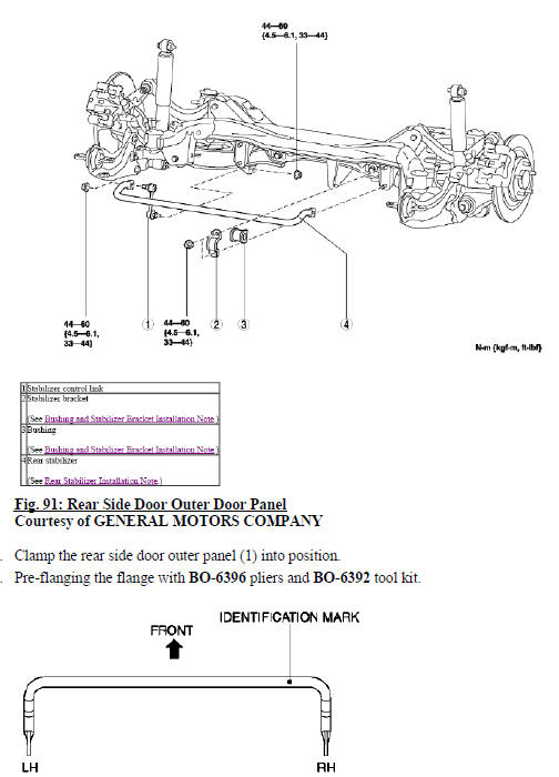
Fig. 92: Rear Side Door Outer Door Panel Hem Flanges
- Continue to hammer in stages along the hem flanges (1).
- Apply the sealers and anti-corrosion materials to the repair area, as necessary. Refer to Anti-Corrosion Treatment and Repair (Base) .
- Install the rear side door outside handle. Refer to Rear Side Door Outside Handle Replacement .
- Install the rear side door. Refer to Rear Side Door Replacement .
- Paint the repaired area. Refer to Basecoat/Clearcoat Paint Systems .
- Install all related panels and components.
- Connect the negative battery cable. Refer to Battery Negative Cable Disconnection and Connection .
- Enable the SIR system. Refer to SIR Disabling and Enabling
Rear compartment floor panel replacement
Removal Procedure
WARNING: Refer to Approved Equipment for Collision Repair Warning .
WARNING: Refer to Glass and Sheet Metal Handling Warning .
- Disable the SIR system. Refer to SIR Disabling and Enabling .
- Disconnect the negative battery cable. Refer to Battery Negative Cable Disconnection and Connection .
- Remove all related panels and components.
- Visually inspect the damage. Repair as much of the damage as possible.
- Remove the sealers and anti-corrosion materials from the repair area, as necessary. Refer to Anti- Corrosion Treatment and Repair (Base) .
- Locate and mark all the necessary factory welds of the rear compartment floor panel.
- Note the number and location of weld studs for installation of the service assembly.
.gif)
Fig. 93: Drilling Factory Welds
- Drill all factory welds (1). Note the number and location of welds for installation of the service assembly.
.gif)
Fig. 94: Rear Compartment Floor Panel
- Remove the damaged rear compartment floor panel (1).
Installation Procedure
- Align the rear compartment floor panel.
.gif)
Fig. 95: Drilling Weld Holes In Rear Compartment Floor Panel
- Drill a 8 mm (5/16 in) holes for plug welding along the edges of the rear compartment floor panel as noted from the original panel (1).
- Clean and prepare the attaching surfaces for welding.
- Position the rear compartment floor panel on the vehicle.
- Verify the fit of the rear compartment floor panel.
- Clamp the rear compartment floor panel into position.
Fig. 96: Plug Welding Rear Compartment Floor Panel
- Plug the weld accordingly (1).
.gif)
Fig. 97: Drill And Required Attachments
- Drill 8 mm (5/16 in) for plug welding along the edges of the floor panel rear reinforcement, the spare wheel carrier bracket, the shipping device and the floor panel reinforcement as noted from the original panel (1).
- Clean and prepare the attaching surfaces for welding.
- Position the floor panel rear reinforcement, the spare wheel carrier bracket, the shipping device and the floor panel reinforcement on the vehicle.
- Verify the fit of the floor panel rear reinforcement, the spare wheel carrier bracket, the shipping device and the floor panel reinforcement.
Fig. 98: Plug Welding Rear Compartment Floor Panel
- Plug weld accordingly (1).
- Weld accordingly the weld studs as noted.
- Apply the sealers and anti-corrosion materials to the repair area, as necessary. Refer to Anti-Corrosion Treatment and Repair (Base) .
- Paint the repaired area. Refer to Basecoat/Clearcoat Paint Systems .
- Install all related panels and components.
- Connect the negative battery cable. Refer to Battery Negative Cable Disconnection and Connection .
- Enable the SIR system. Refer to SIR Disabling and Enabling .
Rear wheelhouse outer panel replacement
Removal Procedure
WARNING: Refer to Approved Equipment for Collision Repair Warning .
WARNING: Refer to Glass and Sheet Metal Handling Warning
- Disable the SIR system. Refer to SIR Disabling and Enabling .
- Disconnect the negative battery cable. Refer to Battery Negative Cable Disconnection and Connection .
- Remove all related panels and components.
- Repair as much of the damage as possible to factory specifications. Refer to Dimensions - Body (Opel, Encore), Dimensions - Body (Encore).
- Remove the sealers and anti-corrosion materials from the repair area, as necessary. Refer to Anti- Corrosion Treatment and Repair (Base) .
- Locate and mark all the necessary factory welds of the rear wheelhouse outer panel.
.gif)
Fig. 99: Drilling Welds From Rear Wheelhouse Outer Panel
- Drill all factory welds (1). Note the number and location of welds for installation of the service assembly.
.gif)
Fig. 100: Rear Wheelhouse Outer Panel
- Remove the damaged rear wheelhouse outer panel (1).
Installation Procedure
- Align the rear wheelhouse outer panel.
.gif)
Fig. 101: Drilling Plug Weld Holes
- Drill a 8 mm (5/16 in) holes for plug welding along the edges of the quarter outer panel (1) as noted from the original panel.
- Clean and prepare the attaching surfaces for welding.
.gif)
Fig. 102: Rear Wheelhouse Outer Panel
- Position the rear wheelhouse outer panel on the vehicle (1).
- Verify the fit of the rear wheelhouse outer panel.
- Clamp the rear wheelhouse outer panel into position.
.gif)
Fig. 103: Plug Welding Rear Wheelhouse Outer Panel
- Plug the weld accordingly (1).
- Apply the sealers and anti-corrosion materials to the repair area, as necessary. Refer to Anti-Corrosion Treatment and Repair (Base) .
- Paint the repaired area. Refer to Basecoat/Clearcoat Paint Systems .
- Install all related panels and components.
- Connect the negative battery cable. Refer to Battery Negative Cable Disconnection and Connection .
- Enable the SIR system. Refer to SIR Disabling and Enabling .
Quarter outer panel sectioning
NOTE: According to different corrosion warranties, only the regional mandatory joining methods are allowed.
Removal Procedure
WARNING: Refer to Approved Equipment for Collision Repair Warning .
WARNING: Refer to Collision Sectioning Warning .
WARNING: Refer to Glass and Sheet Metal Handling Warning .
- Disable the SIR System. Refer to SIR Disabling and Enabling .
- Disconnect the negative battery cable. Refer to Battery Negative Cable Disconnection and Connection .
- Remove all related panels and components.
- Visually inspect the damage. Repair as much of the damage as possible.
- Remove the sealers and anti-corrosion materials from the repair area, as necessary. Refer to Anti- Corrosion Treatment and Repair (Base) .
.gif)
Fig. 104: Cut Lines For Quarter Outer Panel
- Create cut lines on the quarter outer panel (1).
.gif)
Fig. 105: Sectioning Quarter Outer Panel
NOTE: Do not damage any inner panels or reinforcements.
- Cut the panel where sectioning is to be performed (1).
- Locate and mark all the necessary factory welds of the quarter outer panel.
.gif)
Fig. 106: Drilling Factory Welds From Quarter Outer Panel
- Drill all factory welds (1). Note the number and location of welds for installation of the service assembly
.gif)
Fig. 107: Quarter Outer Panel
- Remove the damaged quarter outer panel (1).
Installation Procedure
.gif)
Fig. 108: Quarter Outer Panel Cut Lines
- Cut the quarter outer panel in corresponding locations to fit the remaining original panel. The sectioning joint should be trimmed to overlap the remaining original panel by 25 mm (1 inch) at each joint location (1).
- Prepare all mating surfaces as necessary.
.gif)
Fig. 109: Drilling Holes In Quarter Outer Panel Cut Lines
- Drill 8 mm (5/16 in) holes for plug welding along the edges of the quarter outer panel as noted from the original panel (1).
- Clean and prepare the attaching surfaces for welding.
.gif)
Fig. 110: Quarter Outer Panel
- Position the quarter outer panel on the vehicle (1).
- Verify the fit of the quarter outer panel.
- Clamp the quarter outer panel into position.
.gif)
Fig. 111: Plug Welding Quarter Outer Panel
- Plug weld accordingly (1).
- To create a solid weld with minimum heat distortion, make 25 mm (1 in) stitch welds along the seam with 25 mm (1 in) gaps between them. Then go back and complete the stitch weld.
- Apply the sealers and anti-corrosion materials to the repair area, as necessary. Refer to Anti-Corrosion Treatment and Repair (Base) .
- Paint the repaired area. Refer to Basecoat/Clearcoat Paint Systems .
- Install all related panels and components.
- Connect the negative battery cable. Refer to Battery Negative Cable Disconnection and Connection .
- Enable the SIR system. Refer to SIR Disabling and Enabling .
Center pillar inner panel replacement
Removal Procedure
WARNING: Refer to Approved Equipment for Collision Repair Warning .
WARNING: Refer to Glass and Sheet Metal Handling Warning .
- Disable the SIR System. Refer to SIR Disabling and Enabling .
- Disconnect the negative battery cable. Refer to Battery Negative Cable Disconnection and Connection .
- Remove all related panels and components.
- Visually inspect the damage. Repair as much of the damage as possible.
- Remove the sealers and anti-corrosion materials from the repair area, as necessary. Refer to Anti- Corrosion Treatment and Repair (Base) .
- Locate and mark all factory welds.
.gif)
Fig. 112: Drilling Factory Welds
- Drill all factory welds (1). Note the number and location of welds for installation of the service assembly
.gif)
Fig. 113: Center Pillar Inner Panel
- Remove the damaged center pillar inner panel (1).
Installation Procedure
- Prepare all mating surfaces as necessary.
- Align the center pillar inner panel.
.gif)
Fig. 114: Drilling Plug Weld Holes
- Drill 8 mm (5/16 in) holes for plug welding along the edges of the center pillar inner panel (1) as noted from the original panel.
- Clean and prepare the attaching surfaces for welding.
.gif)
Fig. 115: Center Pillar Inner Panel
- Position the center pillar inner panel on the vehicle (1).
- Verify the fit of the center pillar inner panel.
- Clamp the center pillar inner panel into position.
.gif)
Fig. 116: Plug Welding Center Pillar Inner Panel
- Plug weld accordingly (1).
- To create a solid weld with minimum heat distortion, make 25 mm (1 in) stitch welds along the seam with 25 mm (1 in) gaps between them. Then go back and complete the stitch weld.
- Apply the sealers and anti-corrosion materials to the repair area, as necessary. Refer to Anti-Corrosion Treatment and Repair (Base) .
- Paint the repaired area. Refer to Basecoat/Clearcoat Paint Systems .
- Install all related panels and components.
- Connect the negative battery cable. Refer to Battery Negative Cable Disconnection and Connection .
- Enable the SIR system. Refer to SIR Disabling and Enabling .
Center pillar reinforcement replacement
Removal Procedure
WARNING: Refer to Approved Equipment for Collision Repair Warning .
WARNING: Refer to Glass and Sheet Metal Handling Warning .
NOTE: The center pillar upper stiffener is made of Dual Phase Steel and should be replaced only at factory joints. Repairing or sectioning of this part is not recommended. Refer to Dual Phase Steel.
- Disable the SIR system. Refer to SIR Disabling and Enabling .
- Disconnect the negative battery cable. Refer to Battery Negative Cable Disconnection and Connection
- Remove all related panels and components.
- Visually inspect the damage. Repair as much of the damage as possible.
- Remove the sealers and anti-corrosion materials from the repair area, as necessary. Refer to Anti- Corrosion Treatment and Repair (Base) .
- Locate and mark all the necessary factory welds of the center pillar reinforcement.
.gif)
Fig. 117: Drilling Factory Welds
- Drill all factory welds (1). Note the number and location of welds for installation of the service assembly
.gif)
Fig. 118: Center Pillar Reinforcement
- Remove the damaged center pillar reinforcement (1).
Installation Procedure
- Prepare all mating surfaces as necessary.
- Align the center pillar reinforcement.
.gif)
Fig. 119: Drilling Plug Weld Holes In Center Pillar Reinforcement
- Drill a 8 mm (5/16 in) holes for plug welding along the edges of the center pillar reinforcement as noted from the original panel (1).
- Clean and prepare the attaching surfaces for welding.
.gif)
Fig. 120: Center Pillar Reinforcement
- Position the center pillar reinforcement on the vehicle (1).
- Verify the fit of the center pillar reinforcement.
- Clamp the center pillar reinforcement into position.
.gif)
Fig. 121: Welding Center Pillar Reinforcement
- Plug weld accordingly (1).
- Apply the sealers and anti-corrosion materials to the repair area, as necessary. Refer to Anti-Corrosion Treatment and Repair (Base) .
- Paint the repaired area. Refer to Basecoat/Clearcoat Paint Systems .
- Install all related panels and components.
- Connect the negative battery cable. Refer to Battery Negative Cable Disconnection and Connection .
- Enable the SIR system. Refer to SIR Disabling and Enabling .
Center pillar sectioning - outer
Removal Procedure
WARNING: Refer to Approved Equipment for Collision Repair Warning .
WARNING: Refer to Collision Sectioning Warning .
WARNING: Refer to Glass and Sheet Metal Handling Warning .
NOTE: This procedure was developed to allow full access for the replacement of the center pillar reinforcement replacement since sectioning is not endorsed or recommended to the reinforcement due to the Ultra High Strength Steel.
- Disable the SIR system. Refer to SIR Disabling and Enabling .
- Disconnect the negative battery cable. Refer to Battery Negative Cable Disconnection and Connection .
- Remove all related panels and components.
- Visually inspect the damage. Repair as much of the damage as possible
- Remove the sealers and anti-corrosion materials from the repair area, as necessary. Refer to Anti- Corrosion Treatment and Repair (Base) .
.gif)
Fig. 122: Center Pillar Weatherstrip
- Remove the weather-strip, observe the flange in the center pillar area.
There will be a 3-metal stack-up.
The center layer is the center pillar reinforcement (1).
.gif)
Fig. 123: Center Pillar Cut Line Marks
- Measure 13 mm (1/2 in) from the forward and rearward edges of the center pillar reinforcement and mark a vertical line.
.gif)
Fig. 124: Measuring Door Opening Feature Line
- Measure up 1 inch from the door opening feature line (1) and mark a horizontal line.
Fig. 125: Cutting Access Window In Center Pillar Outer
- Cut access window (1) in the center pillar outer.
- Perform additional sectioning procedures as needed depending on damage to vehicle. Refer to Rocker Outer Panel Sectioning, or Front Hinge Pillar Body Sectioning.
Fig. 126: Drilling Out Factory Welds
- Locate and drill out all factory welds (1). Note the number and location of welds for installation of the service part.
Fig. 127: Center Pillar Outer Panel Section
- Remove the damaged center pillar outer panel section.
Installation Procedure
Fig. 128: Center Pillar Outer Panel Section Cut Points
- From the service part, cut the panel in corresponding locations to overlap the remaining original panel by 25 mm (1 in) at each joint location (1).
Fig. 129: Drilling Center Pillar Outer Panel Section Plug Weld Holes
- Drill 8 mm (5/16 in) holes for plug welding in the service part (1), as necessary, in the corresponding locations noted on the original panel and along sectioned joint.
- Clean and prepare the attaching surfaces for welding.
Fig. 130: Center Pillar Outer Panel Section
- Position the center pillar outer panel to the vehicle. Clamp the pillar in place.
Fig. 131: Plug Welding Center Pillar Outer Panel Section
- Plug weld accordingly (1).
Fig. 132: Solid Welding Center Pillar Outer Panel Section
- To create a solid weld with minimum heat distortion, make a 25 mm (1 in) stitch weld along the seam with gaps of 25 mm (1 in) gaps between them. Go back and complete the stitch weld (1).
- Clean and prepare all of the welded surfaces
- Apply the sealers and anti-corrosion materials to the repair area, as necessary. Refer to Anti-Corrosion Treatment and Repair (Base) .
- Paint the repaired area. Refer to Basecoat/Clearcoat Paint Systems .
- Install all related panels and components.
- Connect the negative battery cable. Refer to Battery Negative Cable Disconnection and Connection .
- Enable the SIR system. Refer to SIR Disabling and Enabling .
Rear rail sectioning
Removal Procedure
WARNING: Refer to Approved Equipment for Collision Repair Warning .
WARNING: Refer to Collision Sectioning Warning
WARNING: Refer to Glass and Sheet Metal Handling Warning .
- Disable the SIR system. Refer to SIR Disabling and Enabling .
- Disconnect the negative battery cable. Refer to Battery Negative Cable Disconnection and Connection .
- Remove all related panels and components.
- Visually inspect the damage. Repair as much of the damage as possible.
- Remove the sealers and anti-corrosion materials from the repair area, as necessary. Refer to Anti- Corrosion Treatment and Repair (Base) .
Fig. 133: Mark On Outer And Inner Lower Surface Of Rear Rail
- Locate the die mark on the outer and inner lower surface of the rear rail.
NOTE: Do not section the rail in any area other than the die mark location given.
- Align a sliding square or similar tool to the line at the tip of the arrow in the die mark. Scribe a line across the rail.
Fig. 134: Cutting Panel
NOTE: Do not damage any other panels or reinforcements.
- Cut the panel where sectioning is to be performed (1).
- Locate and mark all the necessary factory welds of the rear side rail.
.gif)
Fig. 135: Drilling Factory Welds
- Drill all factory welds (1). Note the number and location of welds for installation of the service assembly
.gif)
Fig. 136: Rear Side Rail
- Remove the damaged rear side rail (1).
.gif)
Fig. 137: Drilling Plug Weld Holes In Rear Side Rail
- Drill two 8 mm (5/16 in) plug weld holes on each of the 3 sides of the rear rail (1). Position the center of the holes 10 mm (3/8 in) from the cut edge.
Installation Procedure
- Locate the original cutting line on the service part rear rail.
- Align a sliding square or similar tool to the original cutting line and scribe a line across the rail.
- Use the same tool to transfer this scribed line onto the sides and the weld flanges of the rail.
- Place a mark forward, 25 mm (1 in) from the scribed line on all 3 sides of the service rail.
- Use the tool to scribe a line on all 3 sides and weld flanges of the rail.
.gif)
Fig. 138: Rear Portion Of Rail
- Cut at the scribe line (1).
- Remove the rear portion of the rail.
.gif)
Fig. 139: Rear Side Rail Outer Flanges
- Cut the upper outer flanges of the rear portion of the rear rail service part. Cut the flanges back to the first scribe line and remove the tabs.
- Cut the lower radius corners of the service part back to the first scribe line and remove the small corners.
- Bend the bottom side of the service part at the sectioning location inward slightly by aligning a vice grip flanging tool or similar tool at the first scribed line.
- Clean and prepare the attaching surfaces for welding.
.gif)
Fig. 140: Rear Side Rail
- Position the rear side rail (1) on the vehicle.
.gif)
Fig. 141: Tack Welding Rear Side Rail
- Tack weld the part into position.
- Inspect the service rear rail for proper dimensions, using 3-dimensional measuring equipment.
- Plug weld at each 8 mm (5/16 in) plug weld hole location.
- Stitch weld along the entire sectioning joint. Make welds along the seam with 25 mm (1 in) gaps between. Weld the gaps.
- Clean and prepare the welded surfaces.
- Apply the sealers and anti-corrosion materials to the repair area, as necessary. Refer to Anti-Corrosion Treatment and Repair (Base) .
- Paint the repaired area. Refer to Basecoat/Clearcoat Paint Systems .
- Install all related panels and components.
- Connect the negative battery cable. Refer to Battery Negative Cable Disconnection and Connection .
- Enable the SIR system. Refer to SIR Disabling and Enabling .
Rear end panel replacement
Removal Procedure
WARNING: Refer to Approved Equipment for Collision Repair Warning .
WARNING: Refer to Glass and Sheet Metal Handling Warning
NOTE: The rear end lower panel reinforcement extension is made of Ultra High Strength Dual Phase Steel and should be replaced only at factory joints.
Repairing or sectioning of this part is not recommended. Refer to Ultra High Strength Dual Phase Steel.
- Disable the SIR System. Refer to SIR Disabling and Enabling .
- Disconnect the negative battery cable. Refer to Battery Negative Cable Disconnection and Connection .
- Remove all related panels and components.
- Visually inspect the damage. Repair as much of the damage as possible.
- Remove the sealers and anti-corrosion materials from the repair area, as necessary. Refer to Anti- Corrosion Treatment and Repair (Base) .
NOTE: Note the number and location of welds for installation of the service assembly.
- Locate and mark all the necessary factory welds of the body rear end panel.
.gif)
Fig. 142: Drilling Factory Welds
- Drill all factory welds (1).
.gif)
Fig. 143: Body Rear End Panel
- Remove the body rear end panel (1).
Installation Procedure
.gif)
Fig. 144: Drilling Plug Weld Holes
NOTE: If the location of the original plug weld holes can not be determined, space the plug weld holes every 40 mm (1 1/2 in).
- Drill 8 mm (5/16 in) holes for plug welding along the edges of the body rear end panel (1) as noted from the original panel.
- Clean and prepare the attaching surfaces for welding.
.gif)
Fig. 145: Body Rear End Panel
- Position the body rear end panel on the vehicle (1).
- Verify the fit of the body rear end panel.
- Clamp the body rear end panel into position.
.gif)
Fig. 146: Welding Body Rear End Panel
- Plug weld accordingly (1).
- Apply the sealers and anti-corrosion materials to the repair area, as necessary. Refer to Anti-Corrosion Treatment and Repair (Base) .
- Paint the repaired area. Refer to Basecoat/Clearcoat Paint Systems .
- Install all related panels and components.
- Connect the negative battery cable. Refer to Battery Negative Cable Disconnection and Connection .
- Enable the SIR system. Refer to SIR Disabling and Enabling .
Body tail lamp filler panel replacement
Removal Procedure
WARNING: Refer to Approved Equipment for Collision Repair Warning .
WARNING: Refer to Glass and Sheet Metal Handling Warning
- Disable the SIR System. Refer to SIR Disabling and Enabling .
- Disconnect the negative battery cable. Refer to Battery Negative Cable Disconnection and Connection .
- Remove all related panels and components.
- Visually inspect the damage. Repair as much of the damage as possible.
- Remove the sealers and anti-corrosion materials from the repair area, as necessary. Refer to Anti- Corrosion Treatment and Repair (Base) .
- Locate and mark all the necessary factory welds of the body tail lamp filler panel.
.gif)
Fig. 147: Drilling Factory Welds
- Drill all factory welds (1). Note the number and location of welds for installation of the service assembly.
.gif)
Fig. 148: Body Tail Lamp Filler Panel
- Remove the body tail lamp filler panel (1).
Installation Procedure
.gif)
Fig. 149: Drilling Body Tail Lamp Filler Panel Plug Weld Holes
- Drill 8 mm (5/16 in) holes for plug welding along the edges of the body rear end panel (1) as noted from the original panel.
- Clean and prepare the attaching surfaces for welding.
.gif)
Fig. 150: Body Tail Lamp Filler Panel
- Position the body tail lamp filler panel on the vehicle (1).
- Verify the fit of the body tail lamp filler panel.
- Clamp the body tail lamp filler panel into position.
.gif)
Fig. 151: Plug Welding Body Tail Lamp Filler Panel
- Plug the weld accordingly (1).
- Apply the sealers and anti-corrosion materials to the repair area, as necessary. Refer to Anti-Corrosion Treatment and Repair (Base) .
- Paint the repaired area. Refer to Basecoat/Clearcoat Paint Systems .
- Install all related panels and components.
- Connect the negative battery cable. Refer to Battery Negative Cable Disconnection and Connection .
- Enable the SIR system. Refer to SIR Disabling and Enabling .
READ NEXT:
 Description and operation
Dual phase steel
This information provides repair recommendations and general guidelines for
steel classified as Dual Phase
Steel (dual phase steel with a tensile strength up to and including 800 MPa
Cabin Air Filter
REMOVAL & INSTALLATION
NOTE: Manufacturer's terminology for this filter is passenger
compartment air filter.
CABIN AIR FILTER
Removal & Installation
Fig. 1: Passenger Compartment Air Filter
SEE MORE:
Description and operation
Rear drive axle description and operation
The rear differential assembly in this vehicle consists of an aluminum
housing which contains a electric
clutch/coupler and a differential. The differential fluid is only contained in
the differential housing portion.
The clutch and clutch housing are serv
Power Seats - Description and operation
Lumbar support description and operation
Lumbar Support Components
The power seat lumbar support systems each consist of the following
components:
Seat lumbar support switch
Lumbar support motor
The seat lumbar support switch provides both power and ground to the lumbar
support motor. The moto
