Buick Encore: Drivetrain and front suspension frame replacement (short cradle)
Removal Procedure
- Raise and support the vehicle. Refer to Lifting and Jacking the Vehicle .
- Remove the front tire and wheel assembly. Refer to Tire and Wheel Removal and Installation .
- Remove the drivetrain and front suspension frame transmission protector from the front frame, if equipped. Refer to Drivetrain and Front Suspension Frame Transmission Protector Replacement.
- Remove the front compartment front center insulator, if equipped. Refer to Front Compartment Front Center Insulator Replacement.
- Disconnect the lower ball joints from the steering knuckles. Refer to Lower Control Arm Replacement .
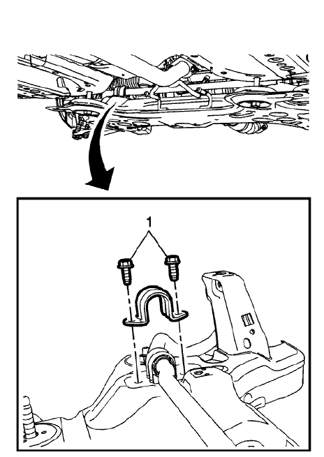
Fig. 17: Stabilizer Shaft Insulator Bracket And Bolts
- Remove the four fasteners (1) retaining the stabilizer shaft to the drivetrain and front suspension.
.gif)
Fig. 18: Steering Rack Retaining Bolts And Exhaust Isolators
- Remove the steering rack retaining fasteners (1) and discard.
- Using mechanics wire, secure the power steering gear and stabilizer shaft to the vehicle.
- Disconnect the hydraulic power steering hoses from the front frame.
- Disconnect the exhaust isolators (2) from the front suspension frame.
- Disconnect the power brake booster pump hose and connector, if equipped.
.gif)
Fig. 19: Transmission Mount Bracket To Rear Mount Through Bolt
- Remove the rear transmission mount bracket to rear mount through fasteners (1).
- Using a suitable support table or equivalent, support the front suspension frame.
.gif)
Fig. 20: Upper Frame Suspension Retaining Bolts
- Remove the two upper frame suspension retaining fasteners (1).
.gif)
Fig. 21: Frame Rear Fasteners
- Remove the two frame rear fasteners (1).
- Remove the frame (2) from the vehicle.
- Remove the following components, if replacing the frame:
- The lower control arms-Refer to Lower Control Arm Replacement .
- The power brake booster pump, if equipped-Refer to Power Brake Booster Pump Replacement .
- The rear transmission mount bracket-Refer to Transmission Mount Bracket Replacement - Rear (AWD) , Transmission Mount Bracket Replacement - Rear (FWD) .
Installation Procedure
- Install the following components on the drivetrain and front suspension frame if removed:
- The rear transmission mount bracket-Refer to Transmission Mount Bracket Replacement - Rear (AWD) , Transmission Mount Bracket Replacement - Rear (FWD) .
- The power brake booster pump, if equipped-Refer to Power Brake Booster Pump Replacement .
- The lower control arms-Refer to Lower Control Arm Replacement
- Install the frame into the vehicle.
.gif)
Fig. 22: Front Suspension Frame And Floor Panel
- Using a commercially available guide pin, have an assistant vertically insert and hold the pins through the front suspension frame and floor panel (1).
.gif)
Fig. 23: Frame Rear Fasteners
CAUTION: Refer to Fastener Caution .
- Install the frame (2) rear fasteners (1) and tighten:
- First Pass:100 (74 lb ft).
- Final Pass: an additional 60 to 75 degrees.
.gif)
Fig. 24: Upper Frame Suspension Retaining Bolts
- Install the two upper frame suspension retaining fasteners (1) and tighten to 135 N.m (100 lb ft).
- Remove the wire retaining the power steering gear and stabilizer shaft to the vehicle.
.gif)
Fig. 25: Steering Rack Retaining Bolts And Exhaust Isolators
- Install the steering gear retaining fasteners (1). Refer to Steering Gear Boot Replacement .
- Connect the hydraulic power steering hoses to the front frame.
- Connect the exhaust isolators (2) to the front suspension frame.
Fig. 26: Transmission Mount Bracket To Rear Mount Through Bolt
- Install the rear transmission mount bracket to rear mount through fasteners (1). Refer to Transmission Rear Mount Replacement (AWD) , Transmission Rear Mount Replacement (FWD) .
- Connect the power brake booster pump hose and connector, if equipped.
- Connect the lower ball joints to the steering knuckles. Refer to Lower Control Arm Replacement
.gif)
Fig. 27: Stabilizer Shaft Insulator Bracket And Bolts
- Connect the stabilizer shaft to the drivetrain and front suspension frame. Refer to Stabilizer Shaft Replacement .
- Install the front compartment front center insulator, if equipped. Refer to Front Compartment Front Center Insulator Replacement.
- Install the drivetrain and front suspension frame transmission protector
to the front frame, if equipped.
Refer to Drivetrain and Front Suspension Frame Transmission Protector Replacement.
- Install the front tire and wheel assembly. Refer to Tire and Wheel Removal and Installation .
- Lower the vehicle.
FRONT WHEELHOUSE LINER REPLACEMENT (ENCORE)
.gif)
Fig. 29: Front Wheelhouse Liner
Front Wheelhouse Liner Replacement (Encore)
.jpg)
REAR WHEELHOUSE LINER REPLACEMENT
.gif)
Fig. 30: Rear Wheelhouse Liner
Rear Wheelhouse Liner Replacement
.jpg)
REAR WHEELHOUSE PANEL AIR DEFLECTOR REPLACEMENT
.gif)
Fig. 31: Rear Wheelhouse Panel Air Deflector
Rear Wheelhouse Panel Air Deflector Replacement
.jpg)
READ NEXT:
 Schematic wiring diagrams
SPECIFICATIONS
FASTENER TIGHTENING SPECIFICATIONS
Fastener Tightening Specifications
SCHEMATIC WIRING DIAGRAMS
HORN WIRING SCHEMATICS (ENCORE)
Fig. 1: Horn (Encore)
HORN WIRING SCHEMATICS (Encore)
Horns - Diagnostic information and procedures
DTC B2750: Horn relay secondary circuit
DIAGNOSTIC CODE INDEX
Diagnostic Instructions
Perform the Diagnostic System Check - Vehicle prior to using this
diagnostic procedure.
Review Strategy Bas
SEE MORE:
Driver Assistance Systems
This vehicle may have features that
work together to help avoid crashes
or reduce crash damage while
driving, backing, and parking. Read
this entire section before using
these systems.
Warning
Do not rely on the Driver
Assistance Systems. These
systems do not replace the need
for paying attention an
Brake rotor/drum balance inspection
Support the vehicle drive axle on a suitable hoist. Refer to Lifting and
Jacking the Vehicle .
Remove the tire and wheel assemblies from the drive axle. Refer to Tire
and Wheel Removal and
Installation .
Reinstall the wheel nuts in order to retain the brake rotors.
Run the vehicle at the c
