Buick Encore: Lighting - Repair instructions
Brake pedal position sensor calibration
NOTE:
Brake system does not use a brake switch, stoplight switch or brakelight switch. System uses a Brake Pedal Position Sensor to control these functions.
Calibration Criteria
NOTE:
Do not apply the brake pedal during the brake pedal position sensor calibration procedure. Any movement of the brake pedal during this procedure will cause the calibration procedure to fail. If this occurs, the brake pedal position sensor calibration must be repeated.
Brake pedal position sensor calibration must be performed after the brake pedal position sensor, body control module (BCM), or engine control module (ECM) have been serviced. The calibration procedure will set the brake pedal position sensor home value. This value is used by the BCM and ECM to determine the action of the driver applying the brake system and to provide this information to the vehicle subsystems via serial data.
Calibration Procedure
- Apply the parking brake.
- Ignition ON, engine OFF, place the transmission in the PARK position for automatic transmission or NEUTRAL position for manual transmission.
- Install a scan tool.
- Clear all DTCs before proceeding.
- Navigate to the Configuration/Reset Functions menu of the BCM.
- Select the Brake Pedal Position Sensor Learn procedure and follow the directions displayed on the screen.
- Navigate to the Configuration/Reset Functions menu of the ECM.
- Select the Learn Functions menu.
- Select the Brake Pedal Position Sensor Learn procedure and follow the directions displayed on the screen.
BRAKE PEDAL POSITION SENSOR REPLACEMENT
NOTE:
Brake system does not use a brake switch, stoplight switch or brakelight switch. System uses a Brake Pedal Position Sensor to control these functions.
Removal Procedure

- Remove the left side front floor air outlet duct. Refer to Floor Front Air Outlet Duct Replacement - Left Side (Encore) , Floor Front Air Outlet Duct Replacement - Left Side (Encore) .
- Disconnect the brake pedal position sensor electrical connector.
- Remove the brake pedal position sensor bolt (1).
.gif)
Fig. 2: Brake Pedal Position Sensor
- Remove the brake pedal position sensor (1).
Installation Procedure

Fig. 3: Brake Pedal Position Sensor
NOTE: Ensure the fork of the brake pedal position sensor is positioned over the brake pedal post.Install the brake pedal position sensor (1).
- Install the brake pedal position sensor (1).
.gif)
Fig. 4: Left Side Front Floor Air Outlet Duct
CAUTION: Refer to Fastener Caution
- Install the brake pedal position sensor bolt (1) and tighten to 3 (27 lb in).
- Install the left side front floor air outlet duct. Refer to Floor Front Air Outlet Duct Replacement - Left Side (Encore) , Floor Front Air Outlet Duct Replacement - Left Side (Encore) .
- Connect the brake pedal position sensor electrical connector.
- Calibrate the brake pedal position sensor. Refer to Brake Pedal Position Sensor Calibration
Headlamp switch replacement (encore)

Fig. 5: Headlamp Switch
Headlamp Switch Replacement (Encore)

HEADLAMP SWITCH REPLACEMENT (Encore)
Fig. 6: Headlamp Switch
Headlamp Switch Replacement (Encore)

HAZARD WARNING SWITCH REPLACEMENT (Encore)

Fig. 7: Hazard Warning Switch
Hazard Warning Switch Replacement (Encore)

HAZARD WARNING AND ACCESSORY SWITCH REPLACEMENT (ENCORE)

Fig. 8: Instrument Panel Airbag Arming Status Display
Hazard Warning and Accessory Switch Replacement (Encore)

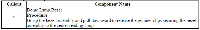
DOME LAMP BEZEL REPLACEMENT

Fig. 9: Dome Lamp Bezel
Dome Lamp Bezel Replacement
Center reading lamp replacement

Fig. 10: Center Reading Lamp
Center Reading Lamp Replacement

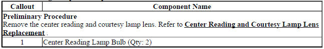
CENTER READING LAMP BULB REPLACEMENT

Fig. 11: Center Reading Lamp Bulb
Center Reading Lamp Bulb Replacement
CENTER READING AND COURTESY LAMP LENS REPLACEMENT

Fig. 12: Center Reading And Courtesy Lamp Lens
Center Reading and Courtesy Lamp Lens Replacement

INSTRUMENT PANEL FLOOD LAMP REPLACEMENT - LEFT SIDE (ENCORE)

Fig. 13: Instrument Panel Flood Lamp - Left Side
Instrument Panel Flood Lamp Replacement - Left Side (Encore)

INSTRUMENT PANEL FLOOD LAMP REPLACEMENT - RIGHT SIDE (ENCORE)

Fig. 14: Instrument Panel Flood Lamp - Right Side
Instrument Panel Flood Lamp Replacement - Right Side (Encore)

Windshield header courtesy lamp replacement
Fig. 15: Windshield Header Courtesy Lamp
Windshield Header Courtesy Lamp Replacement
.jpg)
REAR SEAT POSITION CENTER COURTESY LAMP REPLACEMENT
.gif)
Fig. 16: Rear Seat Position Center Courtesy Lamp
Rear Seat Position Center Courtesy Lamp Replacement
.jpg)
SUNSHADE ILLUMINATED MIRROR LAMP BULB REPLACEMENT (ENCORE)

Fig. 17: Sunshade Illuminated Mirror Lamp Bulb
Sunshade Illuminated Mirror Lamp Bulb Replacement (Encore)

SUNSHADE ILLUMINATED MIRROR LAMP BULB REPLACEMENT (Encore)

Fig. 18: Sunshade Illuminated Mirror Lamp Bulb
Sunshade Illuminated Mirror Lamp Bulb Replacement (Encore)

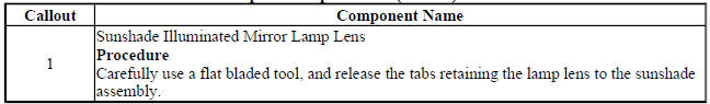
SUNSHADE ILLUMINATED MIRROR LAMP LENS REPLACEMENT (ENCORE)

Fig. 19: Sunshade Illuminated Mirror Lamp Lens
Sunshade Illuminated Mirror Lamp Lens Replacement (Encore)
SUNSHADE ILLUMINATED MIRROR LAMP LENS REPLACEMENT (Encore)

Fig. 20: Sunshade Illuminated Mirror Lamp Lens
Sunshade Illuminated Mirror Lamp Lens Replacement (Encore)

DOME LAMP BULB REPLACEMENT
Fig. 21: Dome Lamp Bulb
Dome Lamp Bulb Replacement
.jpg)
OUTSIDE REARVIEW MIRROR TURN SIGNAL LAMP REPLACEMENT
.gif)
Fig. 22: Outside Rearview Mirror Turn Signal Lamp
Outside Rearview Mirror Turn Signal Lamp Replacement
.jpg)
Headlamp replacement

Fig. 23: Headlamp
Headlamp Replacement

.jpg)
HEADLAMP BULB REPLACEMENT - LEFT SIDE (Encore HIGH BEAM)
.gif)
Fig. 24: Headlamp Bulb - Left Side (High Beam)
Headlamp Bulb Replacement - Left Side (Encore High Beam)
.jpg)
.jpg)
HEADLAMP BULB REPLACEMENT - LEFT SIDE (Encore LOW BEAM)

Fig. 25: Headlamp Bulb - Left Side (Low Beam)
Headlamp Bulb Replacement - Left Side (Encore Low Beam)
.jpg)
.jpg)
HEADLAMP BULB REPLACEMENT - RIGHT SIDE (HIGH BEAM)
.gif)
Fig. 26: Headlamp Bulb - Right Side (High Beam)
Headlamp Bulb Replacement - Right Side (High Beam)
.jpg)
.gif)
HEADLAMP BULB REPLACEMENT - RIGHT SIDE (LOW BEAM)

Fig. 27: Headlamp Bulb - Right Side (Low Beam)
Headlamp Bulb Replacement - Right Side (Low Beam)
.jpg)
HEADLAMP BRACKET REPLACEMENT

Fig. 28: Headlamp Bracket
Headlamp Bracket Replacement
.jpg)
Headlamp aiming
Visual Aiming Preparation Procedure
NOTE: Some state and local laws specify requirements for headlamp aim. Comply with all of these laws when performing any headlamp aiming operations.
Headlamp aim should be checked:
- When a new headlamp capsule is installed.
- If service or repairs to the front end area have, or may have, disturbed the headlamps or their mounting.
The aiming screen should meet the following criteria:
- The area will consist of a level surface large enough to allow for a vehicle and an additional 7.62 m (25 ft) measured from face of lamps to the front of the aiming screen.
- The screen will be 1.52 m (5 ft) high x 3.66 m (12 ft) wide with a matte white surface well shaded from extraneous light, and properly adjusted to the floor on which the vehicle stands. Provisions should be made to align the aiming screen parallel with the vehicle.
- The screen shall be provided with a fixed vertical centerline, two
laterally adjustable vertical tapes, and
one vertically adjustable horizontal tape.
If a regular commercial aiming screen is not available, the screen may consist of a vertical wall having a clear uninterrupted area approximately 1.83 m (6 ft) high and 3.66 m (12 ft) wide. The surface should be finished with a washable non-gloss white paint.
.gif)
Fig. 29: Headlamp Alignment Screen
After the aiming screen has been set up in a permanent location, paint a reference line on the floor directly under the lens of the lamps to indicate the proper location of the headlamps when they are being aimed:
- Adjustable horizontal tape (1)
- Adjustable vertical pointer (2)
- Diagram of light screen (3)
- Distance between headlamps (4)
- Center line of screen (5)
- Horizontal center line of lamps (6)
- 7.62 m (25 ft) (7)
- Car axis (8)
- Horizontal center line ahead of left headlamp (9)
Prior to aiming the headlamps, the following steps must be taken:
- Remove any snow, ice or mud from the vehicle.
- The vehicle must have a full tank of gas.
- Stop all other work on the vehicle.
- If any service has been performed on the vehicle, make sure that all of the components are back in their original place.
- The vehicle must be on a level surface.
- The vehicle left tires must be aligned with the reference line extending from the screen with the headlamps aligned with the reference line.
- Do not load any cargo in the vehicle.
- The vehicle must contain approximately 75 kg (165 lb) on the driver seat.
- Inflate the tires to the proper pressure.
- Simulate the vehicle loads if the intended use of the vehicle is for hauling heavy loads or towing a trailer.
- Rock the vehicle in order to stabilize the suspension.
- Turn on the headlamps to low beam and observe the left and the top edges of the high intensity zone on the screen. The edges of the high intensity zone should fall within the specifications.
Headlamp Aiming Procedure
Fig. 30: Headlamp Alignment Screen Marks
- Open the hood.
- Measure from the floor to the center of the headlamp bulb. Some headlamps have an aim dot marked on the headlamp lens.
- At the screen, measure from the floor and place the horizontal tape at the measured distance.
- Measure from the reference line on the floor to the left headlamp bulb centerline.
- At the screen (1), measure from the reference line and place the vertical tape at the measured distance.
- Measure from the reference line on the floor to the right headlamp bulb centerline.
- At the screen, measure from the reference line and place the vertical tape (2) at the measured distance.
.gif)
Fig. 31: Identifying Right Side Low Beam Proper Screen Positioning
NOTE: DO NOT cover the headlamp. This may cause excessive heat build up.
- Turn ON the low beam headlamps. Block the light from projecting onto the screen from the passenger side headlamp.
.gif)
Fig. 32: Headlamp Adjustment Screws
- Adjust the vertical aim screw ( as shown by the arrow ) of the headlamps to the specifications required by the state and the local authorities, or as shown in step number 8.
- Repeat the aiming procedure for the passenger side headlamp while blocking the light from projecting onto the screen from the driver side headlamp.
- Turn the headlamps OFF.
- Close the hood.
Front fog lamp replacement (Encore)
.gif)
Fig. 33: Front Fog Lamp
Front Fog Lamp Replacement (Encore)
.jpg)
.jpg)
FRONT FOG LAMP REPLACEMENT (ENCORE)
.gif)
Fig. 34: Front Fog Lamp
Front Fog Lamp Replacement (Encore)
.jpg)
.jpg)
FRONT FOG LAMP BULB REPLACEMENT (Encore)
.gif)
Fig. 35: Front Fog Lamp Bulb
Front Fog Lamp Bulb Replacement (Encore)
.jpg)
.jpg)
FRONT FOG LAMP BULB REPLACEMENT (ENCORE)
.gif)
Fig. 36: Front Fog Lamp Bulb
Front Fog Lamp Bulb Replacement (Encore)
.jpg)
FRONT FOG LAMP COVER REPLACEMENT (Encore EXCEPT T3U)
.gif)
Fig. 37: Front Fog Lamp Cover (Encore Except T3U)
Front Fog Lamp Cover Replacement (Encore Except T3U)
.jpg)
FRONT FOG LAMP COVER REPLACEMENT (Encore WITH T3U)
.gif)
Fig. 38: Front Fog Lamp Cover (Encore With T3U)
Front Fog Lamp Cover Replacement (Encore With T3U)
.jpg)
FRONT FOG LAMP COVER REPLACEMENT (ENCORE)

Fig. 39: Front Fog Lamp Cover
Front Fog Lamp Cover Replacement (Encore)
.jpg)
FRONT FOG LAMP OPENING COVER REPLACEMENT (ENCORE)
.gif)
Fig. 40: Front Fog Lamp Opening Cover
Front Fog Lamp Opening Cover Replacement (Encore)
.jpg)
Fog lamp aiming
Preparation Procedure
NOTE:
Horizontal aim is not adjustable on this vehicle. Adjust the fog lamp as required using the adjusting screw above the projector lens on the outside of the front bumper fascia. Prior to aiming the fog lamps, perform the following steps:
- Completely assemble all of the components on the vehicle.
- Place the vehicle on a level surface.
- Stop all unnecessary operations or work that could affect the ride height of the vehicle.
- Close the doors and verify that the luggage compartment is empty.
- Stabilize the suspension by rocking the vehicle sideways.
- Ensure that the fuel level is full.
- Ensure that the tires are inflated to the proper pressure.
- Ensure that the driver or a similar weight, approximately 75 kg (165 lb), is in the vehicle driver seat.
Aiming Procedure

Fig. 41: Headlamp Aiming Distances
- Park the vehicle 7.6 m (25 ft) away from the target screen (a).
- Measure the distance from the center of the fog lamp to the ground line (b).
- Using this measurement, mark the horizontal centerline (1) of the fog lamp on the target screen directly in front of the vehicle.
- Turn ON the fog lamps.
- The top of the fog lamp beam image (2) on the target screen should be 102 mm (4 in) below the center of the fog lamp lens height (1).
- Adjust the fog lamp as required using the adjusting screw above the projector lens on the outside of the front bumper fascia.
- After the adjustments are made, turn OFF the fog lamps.
FRONT TURN SIGNAL LAMP BULB REPLACEMENT (LEFT HAND)
.gif)
Fig. 42: Front Turn Signal Lamp Bulb (Left Hand)
Front Turn Signal Lamp Bulb Replacement (Left hand)
.jpg)
FRONT TURN SIGNAL LAMP BULB REPLACEMENT (RIGHT HAND)
.gif)
Fig. 43: Front Turn Signal Lamp Bulb (Right Hand)
Front Turn Signal Lamp Bulb Replacement (Right Hand)
.jpg)
PARKING AND TURN SIGNAL LAMP BULB REPLACEMENT (LEFT HAND)

Fig. 44: Parking and Turn Signal Lamp Bulb (Left Hand)
Parking and Turn Signal Lamp Bulb Replacement (Left Hand)

PARKING AND TURN SIGNAL LAMP BULB REPLACEMENT (RIGHT HAND)
Fig. 45: Parking and Turn Signal Lamp Bulb (Right Hand)
Parking and Turn Signal Lamp Bulb Replacement (Right Hand)
.jpg)
HIGH MOUNT STOP LAMP REPLACEMENT
.gif)
Fig. 46: High Mount Stop Lamp
High Mount Stop Lamp Replacement
.jpg)
CARGO LAMP REPLACEMENT
.gif)
Fig. 47: Cargo Lamp
Cargo Lamp Replacement
.jpg)
CARGO CENTER COURTESY LAMP BULB REPLACEMENT
.gif)
Fig. 48: Cargo Center Courtesy Lamp Bulb
Cargo Center Courtesy Lamp Bulb Replacement
.jpg)
BACKUP LAMP BULB REPLACEMENT (Encore)
.gif)
Fig. 49: Backup Lamp Bulb (Encore)
Backup Lamp Bulb Replacement (Encore)
.jpg)
BACKUP LAMP BULB REPLACEMENT (ENCORE)
.gif)
Fig. 50: Backup Lamp Bulb (Encore)
Backup Lamp Bulb Replacement (Encore)
.jpg)
REAR LICENSE PLATE LAMP REPLACEMENT
.gif)
Fig. 51: Rear License Plate Lamp
Rear License Plate Lamp Replacement
.jpg)
REAR LICENSE PLATE LAMP BULB REPLACEMENT
.gif)
Fig. 52: Rear License Plate Lamp Bulb
Rear License Plate Lamp Bulb Replacement
.jpg)
REAR LICENSE PLATE LAMP WIRING HARNESS REPLACEMENT
.gif)
Fig. 53: Rear License Plate Lamp Wiring Harness
Rear License Plate Lamp Wiring Harness Replacement
.jpg)
TAIL LAMP REPLACEMENT (Encore)
.gif)
Fig. 54: Tail Lamp (Encore)
Tail Lamp Replacement (Encore)
.jpg)
TAIL LAMP REPLACEMENT (ENCORE)
.gif)
Fig. 55: Tail Lamp (Encore)
Tail Lamp Replacement (Encore)
.jpg)
.jpg)
STOP AND TAIL LAMP BULB REPLACEMENT (Encore)
.gif)
Fig. 56: Stop and Tail Lamp Bulb (Encore)
Stop and Tail Lamp Bulb Replacement (Encore)
.jpg)
.jpg)
STOP AND TAIL LAMP BULB REPLACEMENT (ENCORE)
.gif)
Fig. 57: Stop And Tail Lamp Bulb (Encore)
Stop and Tail Lamp Bulb Replacement (Encore)
.jpg)
.gif)
REAR TURN SIGNAL LAMP BULB REPLACEMENT (Encore)
.gif)
Fig. 58: Rear Turn Signal Lamp Bulb (Encore)
Rear Turn Signal Lamp Bulb Replacement (Encore)
.jpg)
REAR TURN SIGNAL LAMP BULB REPLACEMENT (ENCORE)
.gif)
Fig. 59: Rear Turn Signal Lamp Bulb (Encore)
Rear Turn Signal Lamp Bulb Replacement (Encore)
.jpg)
READ NEXT:
 Schematic wiring diagrams
HEADLIGHTS/DAYTIME RUNNING LIGHTS (DRL) WIRING SCHEMATICS (ENCORE)
Controls and Indicators
Fig. 1: Controls and Indicators
HeadLamps
Fig. 2: HeadLamps
Leveling (TR6)
Fig. 3: Leveling (TR6)
HEADL
Schematic wiring diagrams
SPECIFICATIONS
FASTENER TIGHTENING SPECIFICATIONS
Fastener Tightening Specifications
Adhesives, Fluids, Lubricants, and Sealers
SCHEMATIC WIRING DIAGRAMS
INSIDE REARVIEW MIRROR WIRING SCHEMATICS (
SEE MORE:
Seat Hardware, Trim, and Upholstery - Repair instructions
Driver or passenger seat removal and installation
SPECIFICATIONS
FASTENER TIGHTENING SPECIFICATIONS
Fastener Tightening Specifications
DIAGNOSTIC INFORMATION AND PROCEDURES
MANUAL SEAT ADJUSTER LOCKS BETWEEN LOCK POSITIONS
Manual Seat Adjuster Locks Between Lock Positions
SEATS - ADJUSTER TRACK
Component locator
DISASSEMBLED VIEWS
Case and Associated Parts
Fig. 1: Disassembled View Of Case & Associated Parts
Transmission Case Assembly - 6T30 - Gen 1
Fig. 2: Transmission Case Assembly -- 6T30 -- Gen 1
Transmission Case Assembly - 6T30 - Gen 2
Fig. 3: Transmission Case Assembly -- 6T30 -- Gen
