Buick Encore: Repair instructions
Odor correction
Eliminating Air Conditioning Odor
- Odors may be emitted from the air conditioning system primarily at start up in hot, humid climates. The following conditions may cause the odor:
- Debris is present in the HVAC module assembly.
- Microbial growth on the evaporator core.
- When the blower motor fan is turned on, the microbial growth may release
an unpleasant musty odor into
the passenger compartment. To remove odors of this type, the microbial
growth must be addressed.
Perform the following procedure:
- Remove evaporator core. Refer to Air Conditioning Evaporator Replacement.
- Clean evaporator core with a solution of 40% vinegar and 60% water.
- Refit evaporator core. Refer to Air Conditioning Evaporator Replacement
REFRIGERANT RECOVERY AND RECHARGING (R-134A)
WARNING: To prevent personal injury, avoid breathing A/C Refrigerant and lubricant vapor or mist. Work in a well ventilated area. To remove refrigerant from the A/C System, use service equipment designed for recovery that is certified to meet the requirements of the appropriate SAE Standards. If an accidental system discharge occurs, ventilate the work area before continuing service. Additional health and safety information may be obtained from the refrigerant, refrigerant recovery, and lubricant manufacturers.
WARNING: For personal protection, goggles and lint-free gloves should be worn and a clean cloth wrapped around fittings, valves, and connections when doing work that includes opening the refrigerant system. If refrigerant comes in contact with any part of the body severe frostbite and personal injury can result. The exposed area should be flushed immediately with cold water and prompt medical help should be obtained.
CAUTION: You must replace the desiccant if the A/C refrigerant system has been open to atmosphere for more than four hours, or if the A/C refrigerant oil has been contaminated. Failure to replace the desiccant will result in damage to the A/C refrigerant system.
CAUTION: To avoid system damage use only R-134a dedicated tools when servicing the A/C system.
CAUTION: R-134a is the only approved refrigerant for use in this vehicle. The use of any other refrigerant may result in poor system performance or component failure.
CAUTION: Use only Polyalkylene Glycol Synthetic Refrigerant Oil (PAG) for internal circulation through the R-134a A/C system and only 525 viscosity mineral oil on fitting threads and O-rings. If lubricants other than those specified are used, compressor failure and/or fitting seizure may result.
CAUTION: R-12 refrigerant and R-134a refrigerant must never be mixed, even in the smallest of amounts, as they are incompatible with each other. If the refrigerants are mixed, compressor failure is likely to occur. Refer to the manufacturer instructions included with the service equipment before servicing.
The A/C service station is a complete air conditioning service center for refrigerant. The service station recovers, recycles, evacuates and recharges A/C refrigerant quickly, accurately and automatically. The unit has a display screen that contains the function controls and displays prompts that will lead the technician through the recover, recycle, evacuate and recharge operations. A/C refrigerant is recovered into and charged out of an internal storage vessel.
The A/C service station has a built in A/C refrigerant identifier that will test for contamination, prior to recovery and will notify the technician if there are foreign gases present in the A/C system. If foreign gases are present, the station will not recover the refrigerant from the A/C system.
For information on the actual equipment, please refer to the manual of the equipment in question.
Always recharge the A/C System with the proper amount of refrigerant. Refer to Refrigerant System Specifications for the correct amount.
A/C Refrigerant System Oil Charge Replenishing
If oil was removed from the A/C system during the recovery process or due to component replacement, the oil must be replenished. Oil can be injected into a charged system. For the proper quantities of oil to add to the A/C refrigerant system, refer to Refrigerant System Specifications.
Air conditioning compressor oil balancing
Draining Procedure
NOTE: Drain and measure as much of the refrigerant oil as possible from the rear head ports of the removed air conditioning compressor.
- Before draining oil, position the compressor vertically, (clutch facing upwards) and let the air conditioning compressor sit for 1 minute.
- Position the air conditioning compressor horizontally with the ports facing downward, rotate the clutch and shake the air conditioning compressor in order to remove as much oil from the air conditioning compressor as possible.
- Drain the oil from both the suction and discharge ports of the removed air conditioning compressor into a clean, graduated container. Rotate the air conditioning compressor shaft to assist in draining the air conditioning compressor.
.gif)
Fig. 1: Draining A/C Refrigerant Oil From Compressor
- Measure and record the amount of oil drained from the removed air conditioning compressor. This measurement will be used during installation of the replacement air conditioning compressor. Inspect oil drained from removed air conditioning compressor. Refer to Air Conditioning Compressor Oil Diagnosis.
- Properly discard the used refrigerant oil.
Balancing Procedure
NOTE: The refrigerant oil in the air conditioning system must be balanced during air conditioning compressor replacement.
- Before installing the air conditioning compressor, the refrigerant oil will have to be fully drained.
.gif)
Fig. 2: Replacing Measured Compressor Oil
- Add back the same quantity of polyalkylene glycol (PAG) oil as drained from the removed air conditioning compressor. Refer to the amount of refrigerant oil recorded during the air conditioning compressor removal.
AIR CONDITIONING COMPRESSOR REPLACEMENT (LUJ, LUV)
.gif)
Fig. 3: Air Conditioning Compressor (LUJ, LUV)
Air Conditioning Compressor Replacement (LUJ, LUV)
.jpg)
.jpg)
Air conditioning compressor replacement (2H0)
.gif)
Fig. 4: Air Conditioning Compressor (2H0)
Air Conditioning Compressor Replacement (2H0)
.jpg)
.jpg)
COMPRESSOR LEAK TESTING (R-134A)
Special Tools
- GE-39400-A Halogen Leak Detector
- GE-41447 R-134A A/C Tracer Dye-Box of 24
- GE-42220 Universal 12V Leak Detection Lamp
- GE-43872 Fluorescent Dye Cleaner
- GE-46297 A/C Dye Injector Kit
- GE-46297-12 Replacement Dye Cartridges
For equivalent regional tools. Refer to Special Tools .
Refrigerant Leak Testing
NOTE: General Motors vehicles are now manufactured with fluorescent dye installed directly into the air conditioning (A/C) system.
The fluorescent dye mixes and flows with the polyalkylene glycol (PAG) oil throughout the refrigerant system.
Verifying some passive leaks may require using the GE-39400-A Halogen Leak Detector , even though the A/C system contains fluorescent dye.
The only time that adding additional fluorescent dye is required is after flushing the A/C system.
Fluorescent Leak Detector
Fluorescent dye will assist in locating any leaks in the A/C system.
NOTE: PAG oil is water soluble.
- Condensation on the evaporator core or the refrigerant lines may wash the PAG oil and fluorescent dye away from the actual leak. Condensation may also carry dye through the HVAC module drain.
- Leaks in the A/C system will be indicated in a light green or yellow color when using the leak detection lamp.
Use the leak detection lamp in the following areas:
- All fittings or connections that use seal washers or O-rings
- All of the A/C components
- The A/C compressor shaft seal
- The A/C hoses and pressure switches
- The HVAC module drain tube, if the evaporator core is suspected of leaking
- The service port sealing caps
The sealing cap is the primary seal for the service ports.
- Follow the instructions supplied with the GE-42220 Universal 12V Leak Detection Lamp.
- To prevent false diagnosis in the future, thoroughly clean the residual dye from any area where leaks were found. Use a rag and the approved GE-43872 Fluorescent Dye Cleaner.
Fluorescent Dye Injection
NOTE:
Use only fluorescent dye approved by General Motors.
- GE-41447 R-134A A/C Tracer Dye-Box of 24 can be poured directly into a removed A/C component.
- GE-46297-12 Replacement Dye Cartridges is injected into the low side port using GE-46297 A/C Dye Injector Kit.
Not all of the fluorescent dyes are compatible with PAG oil. Some types of dye decrease the oil viscosity or may chemically react with the oil.
R-134A leak detection dye requires time to work. Depending upon the leak rate, a leak may not become visible for between 15 minutes and 7 days.
NOTE: Do NOT overcharge the A/C system with dye. Use only one 7.39 ml (0.25 oz) charge.
- To prevent false diagnosis, thoroughly clean any residual dye from the service port with a rag and the approved fluorescent dye cleaner GE-43872 Fluorescent Dye Cleaner.
Halogen Leak Detector
WARNING: Do not operate the detector in a combustible atmosphere since its sensor operates at high temperatures or personal injury and/or damage to the equipment may result.
Ensure that the vehicle has at least 0.45 kg (1 lb) of refrigerant in the A/C refrigeration system in order to perform a leak test. Refer to Refrigerant Recovery and Recharging (R-134a) for recharging the A/C system.
NOTE:
Halogen leak detectors are sensitive to the following items:
- Windshield washing solutions
- Many solvents and cleaners
- Some adhesives used in the vehicle
Clean and dry all surfaces in order to prevent a false warning. Liquids will damage the detector.
NOTE: Follow a continuous path in order to ensure that you will not miss any possible leaks. Test all areas of the system for leaks.
Follow the instructions supplied with the GE-39400-A Halogen Leak Detector.
Air conditioning clutch assembly replacement (LUJ, LUV)
.gif)
Fig. 5: Air Conditioning Clutch Assembly (LUJ, LUV)
Air Conditioning Clutch Assembly Replacement (LUJ, LUV)
.jpg)
AIR CONDITIONING CLUTCH ASSEMBLY REPLACEMENT (2H0)
.gif)
Fig. 6: Air Conditioning Clutch Assembly
Air Conditioning Clutch Assembly Replacement (2H0)
.jpg)
.jpg)
COMPRESSOR PRESSURE RELIEF VALVE REPLACEMENT (LUJ, LUV)
.gif)
Fig. 7: Compressor Pressure Relief Valve (LUJ, LUV)
Compressor Pressure Relief Valve Replacement (LUJ, LUV)
.jpg)
COMPRESSOR PRESSURE RELIEF VALVE REPLACEMENT (2HO)
.gif)
Fig. 8: Compressor Pressure Relief Valve (2HO)
Compressor Pressure Relief Valve Replacement (2HO)
.jpg)
AIR CONDITIONING COMPRESSOR BRACKET REPLACEMENT (LUJ, LUV)
.gif)
Fig. 9: Air Conditioning Compressor Bracket
Air Conditioning Compressor Bracket Replacement (LUJ, LUV)
.jpg)
AIR CONDITIONING COMPRESSOR BRACKET REPLACEMENT (2H0)
.gif)
Fig. 10: Air Conditioning Compressor Bracket
Air Conditioning Compressor Bracket Replacement (2H0)
.jpg)
Air conditioning system seal replacement
Removal Procedure
- Disassemble the A/C refrigerant components. Refer to the appropriate repair procedure.
NOTE: Cap or tape the open A/C refrigerant components immediately to prevent system contamination.
- Cap or tape the A/C refrigerant components
.gif)
Fig. 11: Sealing Washer
- Remove the sealing washer (1) from the A/C refrigerant component.
- Inspect the seal washer for signs of damage to help determine the root cause of the failure.
- Inspect the A/C refrigerant components for damage or burrs. Repair if necessary.
NOTE: DO NOT reuse sealing washer.
- DISCARD the sealing washer.
Installation Procedure
NOTE: Flat washer type seals do not require lubrication.
- Inspect the new sealing washer for any signs of cracks, cuts, or damage.
Do not use a damaged sealing washer.
- Remove the cap or tape from the A/C refrigerant components.
.gif)
Fig. 12: Identifying Proper Seating Of A/C Refrigerant O-Ring
- Using a lint-free clean, dry cloth, clean the sealing surfaces of the A/C refrigerant components.
- Carefully install the NEW sealing washer (1) onto the A/C refrigerant component.
The sealing washer (1) must completely bottom against the surface of the fitting.
NOTE: After tightening the A/C components, there should be a slight sealing gap of approximately 1.2 mm (3/64 in) between the A/C line and the A/C component.
- Assemble the remaining A/C refrigerant components. Refer to the appropriate repair procedure.
AIR CONDITIONING O-RING SEAL REPLACEMENT
Removal Procedure
- Disassemble the A/C refrigerant components. Refer to the appropriate repair procedure.
- Remove the O-ring seal from the A/C refrigerant component.
- Inspect the O-ring seal for signs of damage to help determine the root cause of the failure.
- Inspect the A/C components for damage or burrs. Repair if necessary.
NOTE: Cap or tape the open A/C refrigerant components immediately to prevent system contamination.
- Cap or tape the A/C refrigerant components.
- Discard the O-ring seal.
Installation Procedure
- Inspect the new O-ring seal for any sign of cracks, cuts, or damage. Replace if necessary.
- Remove the cap or tape from the A/C refrigerant components.
- Using a lint-free clean, dry cloth, carefully clean the sealing surfaces of the A/C refrigerant components
NOTE: DO NOT allow any of the mineral base 525 viscosity refrigerant oil on the new O-ring seal to enter the refrigerant system.
- Lightly coat the new O-ring seal with mineral base 525 viscosity refrigerant oil.
NOTE: DO NOT reuse O-ring seals.
- Carefully slide the new O-ring seal onto the A/C refrigerant component.
.gif)
Fig. 13: O-ring
- The O-ring seal (1) must be fully seated.
- Assemble the A/C components.
Air conditioning compressor hose replacement (LUJ, LUV)
.gif)
Fig. 14: Air Conditioning Compressor Hose
Air Conditioning Compressor Hose Replacement (LUJ, LUV)
.jpg)
.jpg)
AIR CONDITIONING COMPRESSOR HOSE REPLACEMENT (2H0)
.gif)
Fig. 15: Air Conditioning Compressor Hose
Air Conditioning Compressor Hose Replacement (2H0)
.jpg)
.jpg)
AIR CONDITIONING CONDENSER HOSE REPLACEMENT (LUJ, LUV)
Removal Procedure
- Recover the refrigerant. Refer to Refrigerant Recovery and Recharging (R-134a).
- Remove the air cleaner assembly. Refer to Air Cleaner Assembly Replacement .
- Disconnect the electrical connector from the air conditioning refrigerant pressure sensor.
.gif)
Fig. 16: Air Conditioning Compressor Hose Assembly
- Remove the air conditioning compressor hose assembly (1) from the air conditioning condenser hose at the evaporator hose assembly and position out of the way. Refer to Air Conditioning Compressor Hose Replacement (LUJ, LUV),
- Remove and discard the old sealing washer (2) and replace with a NEW sealing washer.
.gif)
Fig. 17: Air Conditioning Condenser Hose Assembly
- Remove the front bumper fascia assembly. Refer to Front Bumper Fascia Replacement (Encore) , Front Bumper Fascia Replacement (Encore) .
- Remove air conditioning condenser hose assembly nut (1) from the air conditioning condenser.
- Remove air conditioning condenser hose assembly (2) from air conditioning condenser.
- Remove and discard the old sealing washers (3) and replace with NEW sealing washers.
.gif)
Fig. 18: Condenser Hose Assembly And Bolt
- Remove air conditioning condenser hose assembly bolt (1) from the air conditioning compressor assembly.
- Remove air conditioning condenser hose assembly (2) from air conditioning compressor assembly.
- Remove and discard the old sealing washers (3) and replace with a NEW sealing washers.
.gif)
Fig. 19: Condenser Hose Assembly
- Remove air conditioning condenser hose assembly (1) from the vehicle.
NOTE: Remove and discard the old air conditioning sealing washers and replace with a NEW sealing washers.
- Transfer all required parts
Installation Procedure
NOTE: Install NEW air conditioning sealing washers to the air conditioning condenser hose assembly. Refer to Air Conditioning System Seal Replacement.
- Install air conditioning condenser hose assembly into the vehicle.
- Install the air conditioning refrigerant pressure sensor. Refer to Air Conditioning (A/C) Refrigerant Pressure Sensor Replacement (LUJ, LUV).
.gif)
Fig. 20: Condenser Hose Assembly And Bolt
- Install NEW air conditioning sealing washer (3) to the air conditioning condenser hose assembly.
- Install the air conditioning condenser hose assembly (2) to the air conditioning compressor assembly.
CAUTION: Refer to Fastener Caution .
- Install air conditioning condenser hose assembly bolt (1) and tighten the bolt to 22 N.m (16 lb ft).
.gif)
Fig. 21: Air Conditioning Condenser Hose Assembly
- Install NEW air conditioning sealing washers (3) to the air conditioning condenser hose assembly.
- Install the air conditioning condenser hose assembly (2) to the air conditioning condenser.
- Install the air conditioning condenser hose assembly nut (1) and tighten the nut to 22 N.m (16 lb ft).
- Install the front fascia assembly. Refer to Front Bumper Fascia Replacement (Encore) , Front Bumper Fascia Replacement (Encore) .
.gif)
Fig. 22: Air Conditioning Compressor Hose Assembly
- Install NEW air conditioning sealing washer (2) to the air conditioning condenser hose assembly.
- Install the air conditioning condenser hose assembly (1) to the evaporator hose assembly.
- Install the air compressor hose assembly to the air conditioning condenser hose assembly (1). Refer to Air Conditioning Compressor Hose Replacement (LUJ, LUV).
- Connect the A/C refrigerant pressure sensor electrical connector.
- Install the air cleaner assembly. Refer to Air Cleaner Assembly Replacement .
- Charge the refrigerant system. Refer to Refrigerant Recovery and Recharging (R-134a).
Air conditioning condenser hose replacement (2H0)
Removal Procedure
- Recover the refrigerant. Refer to Refrigerant Recovery and Recharging (R-134a).
- Remove the air cleaner inlet duct. Refer to Air Cleaner Inlet Duct Replacement (2H0).
.gif)
Fig. 23: Condenser Hose Assembly And Evaporator Hose Assembly
- Remove the air conditioning compressor hose assembly from the air conditioning condenser hose at the evaporator hose assembly and position out of the way. Refer to Air Conditioning Compressor Hose Replacement (2H0),
- Remove the air conditioning condenser hose assembly (1) from the evaporator hose assembly.
- Remove and discard the old sealing washers (2) and replace with NEW sealing washers.
.gif)
Fig. 24: Air Conditioning Condenser Hose Assembly
- Disconnect the electrical connector from the air conditioning refrigerant pressure sensor.
- Remove air conditioning condenser hose assembly bolt (1) from the air conditioning compressor.
- Remove air conditioning condenser hose assembly (2) from the air conditioning compressor.
- Remove and discard the old sealing washers (3) and replace with NEW sealing washers.
.gif)
Fig. 25: Condenser Hose Assembly And Sealing Washers
- Remove the front bumper fascia. Refer to Front Bumper Fascia Replacement (Encore) , Front Bumper Fascia Replacement (Encore) .
- Remove air conditioning condenser hose assembly nut (1) from the air conditioning condenser.
- Remove air conditioning condenser hose assembly (2) from air conditioning condenser.
- Remove and discard the old sealing washers (3) and replace with NEW sealing washers.
.gif)
Fig. 26: Removing Air Conditioning Condenser Hose Assembly
- Remove air conditioning condenser hose assembly (1) from the vehicle.
- Transfer all required parts
Installation Procedure
NOTE: Install NEW air conditioning sealing washers to the air conditioning condenser hose assembly. Refer to Air Conditioning System Seal Replacement.
- Install the air conditioning refrigerant pressure sensor if removed. Refer to Air Conditioning (A/C) Refrigerant Pressure Sensor Replacement (2H0).
- Install air conditioning condenser hose assembly into the vehicle.
.gif)
Fig. 27: Condenser Hose Assembly And Sealing Washers
- Install NEW air conditioning sealing washer (3) to the air conditioning condenser hose assembly (2).
- Install the air conditioning condenser hose assembly (2) to the air conditioning condenser assembly.
CAUTION: Refer to Fastener Caution .
- Install air conditioning condenser hose assembly nut (1) and tighten the nut to 22 N.m (16 lb ft).
- Install the front bumper fascia. Refer to Front Bumper Fascia Replacement (Encore) , Front Bumper Fascia Replacement (Encore) .
.gif)
Fig. 28: Air Conditioning Condenser Hose Assembly
- Install NEW air conditioning sealing washers (3) to the air conditioning condenser hose assembly.
- Install the air conditioning condenser hose assembly (2) to the air conditioning compressor assembly.
- Install the air conditioning condenser hose assembly bolt (1) and tighten the bolt to 22 N.m (16 lb ft).
- Connect the electrical connector to the air conditioning refrigerant pressure sensor.
.gif)
Fig. 29: Condenser Hose Assembly And Evaporator Hose Assembly
- Install NEW air conditioning sealing washer (2) to the air conditioning condenser hose assembly (1).
- Install the air conditioning condenser hose assembly (1) to the evaporator hose assembly.
- Install the air compressor hose assembly to the air conditioning condenser hose assembly. Refer to Air Conditioning Compressor Hose Replacement (2H0).
- Install the air cleaner inlet duct. Refer to Air Cleaner Inlet Duct Replacement (2H0).
- Charge the refrigerant system. Refer to Refrigerant Recovery and Recharging (R-134a).
Air conditioning evaporator hose assembly replacement (LUJ, LUV)
.gif)
Fig. 30: Air Conditioning Evaporator Hose Assembly
Air Conditioning Evaporator Hose Assembly Replacement (LUJ, LUV)
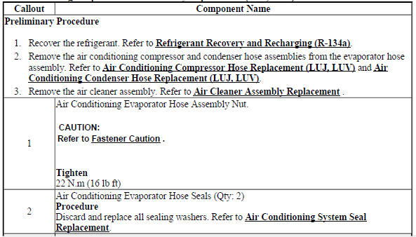

AIR CONDITIONING EVAPORATOR HOSE ASSEMBLY REPLACEMENT (2H0)
.gif)
Fig. 31: Air Conditioning Evaporator Hose Assembly (2H0)
Air Conditioning Evaporator Hose Assembly Replacement (2H0)


AIR CONDITIONING REFRIGERANT SERVICE VALVE CORE REPLACEMENT
Special Tools
- GE 50078 Electronic Leak Detector
- GE 46246 Valve Core Tool
For equivalent regional tools. Refer to Special Tools.
Removal Procedure
.gif)
Fig. 32: Valve Core
- Recover the refrigerant from the A/C system. Refer to Refrigerant Recovery and Recharging (R-134a).
- Using the GE 46246 Valve Core Tool , remove the valve core (1) from the service port.
Installation Procedure
.gif)
Fig. 33: Valve Core
CAUTION: Refer to Fastener Caution .
- Install the valve core (1) to the service port.
- Using the GE 46246 Valve Core Tool , tighten the valve core.
- Evacuate and recharge the A/C system. Refer to Refrigerant Recovery and Recharging (R-134a).
- Leak test the fittings of the component using GE 50078 Electronic Leak Detector.
AIR CONDITIONING REFRIGERANT DESICCANT REPLACEMENT (LUJ, LUV)
.gif)
Fig. 34: Air Conditioning Refrigerant Desiccant
Air Conditioning Refrigerant Desiccant Replacement (LUJ, LUV)

AIR CONDITIONING REFRIGERANT DESICCANT REPLACEMENT (2H0)
.gif)
Fig. 35: Air Conditioning Refrigerant Desiccant (2H0)
Air Conditioning Refrigerant Desiccant Replacement (2H0)

AIR CONDITIONING EVAPORATOR THERMAL EXPANSION VALVE REPLACEMENT (LUJ, LUV)
.gif)
Fig. 36: Air Conditioning Evaporator Thermal Expansion Valve
Air Conditioning Evaporator Thermal Expansion Valve Replacement (LUJ, LUV)

AIR CONDITIONING EVAPORATOR THERMAL EXPANSION VALVE REPLACEMENT (2H0)
.gif)
Fig. 37: Air Conditioning Evaporator Thermal Expansion Valve (2H0)
Air Conditioning Evaporator Thermal Expansion Valve Replacement (2H0)
.jpg)

Air conditioning (a/c) refrigerant pressure sensor replacement (LUJ, LUV)
.gif)
Fig. 38: Air Conditioning (A/C) Refrigerant Pressure Sensor
Air Conditioning (A/C) Refrigerant Pressure Sensor Replacement (LUJ, LUV)
.jpg)
.gif)
AIR CONDITIONING (A/C) REFRIGERANT PRESSURE SENSOR REPLACEMENT (2H0)
.gif)
Fig. 39: Air Conditioning (A/C) Refrigerant Pressure Sensor (LDE/LUW/LWE)
Air Conditioning (A/C) Refrigerant Pressure Sensor Replacement (2H0)
.jpg)

AIR CONDITIONING EVAPORATOR TEMPERATURE SENSOR REPLACEMENT (5 SENSOR RPO CJ2 LHD)
.gif)
Fig. 40: Air Conditioning Evaporator Temperature Sensor (5 Sensor RPO CJ2 LHD)
Air Conditioning Evaporator Temperature Sensor Replacement (5 Sensor RPO CJ2 LHD)
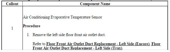

AIR CONDITIONING EVAPORATOR TEMPERATURE SENSOR REPLACEMENT (WITH RPO C67 LHD)
.gif)
Fig. 41: Air Conditioning Evaporator Temperature Sensor (With RPO C67 LHD)
Air Conditioning Evaporator Temperature Sensor Replacement (With RPO C67 LHD)

AIR CONDITIONING CONDENSER REPLACEMENT (LUV)
.gif)
Fig. 42: Air Conditioning Condenser
Air Conditioning Condenser Replacement (LUV)
.jpg)
.jpg)
Heater and air conditioning evaporator and blower module removal and installation
Removal Procedure
- Disconnect the negative battery cable. Refer to Battery Negative Cable Disconnection and Connection .
- Recover the refrigerant system. Refer to Refrigerant Recovery and Recharging (R-134a).
- Drain the engine coolant system. Refer to Cooling System Draining and Filling .
- Remove the heater inlet hose from the heater core tube. Refer to Heater Inlet Hose Replacement (LUJ, LUV), Heater Inlet Hose Replacement (2H0).
- Remove the heater outlet hose from the heater core tube. Refer to Heater Outlet Hose Replacement (2H0), Heater Outlet Hose Replacement (LUJ, LUV), Heater Outlet Hose Replacement (LUJ, LUV Rear).
- Remove the evaporator hose assembly from the thermal expansion valve. Refer to Air Conditioning Evaporator Hose Assembly Replacement (LUJ, LUV), Air Conditioning Evaporator Hose Assembly Replacement (2H0).
- Remove the right side floor rear air outlet duct. Refer to Floor Front Air Outlet Duct Replacement - Right Side.
- Remove the left side floor rear air outlet duct. Refer to Floor Front Air Outlet Duct Replacement - Left Side (Encore), Floor Front Air Outlet Duct Replacement - Left Side (Encore).
- Remove the instrument panel tie bar assembly. Refer to Instrument Panel Tie Bar Replacement .
.gif)
Fig. 43: HVAC Module Assembly Drain Tube
- Remove the Heating Ventilation and Air Conditioning (HVAC) module assembly drain tube (1) from the HVAC module assembly.
.gif)
Fig. 44: HVAC Module Assembly And Cowl Panel
- From within the engine compartment, remove the HVAC module assembly nut, (1) securing the HVAC module assembly to the cowl panel.
.gif)
Fig. 45: HVAC Module Assembly
- Remove the HVAC module assembly (1) from the vehicle.
- Transfer all necessary components.
Installation Procedure
.gif)
Fig. 46: HVAC Module Assembly
- Position the HVAC module assembly (1) into the vehicle and temporarily support it.
.gif)
Fig. 47: HVAC Module Assembly And Cowl Panel
CAUTION: Refer to Fastener Caution .
- From within the engine compartment, install the HVAC module assembly nut (1) securing the HVAC module assembly to the cowl panel, and tighten to 22 (16 lb ft)
.gif)
Fig. 48: HVAC Module Assembly Drain Tube
- Install the HVAC module assembly drain tube (1) to the HVAC module assembly.
- Install the instrument panel tie bar assembly. Refer to Instrument Panel Tie Bar Replacement .
- Install the left side floor rear air outlet duct. Refer to Floor Front Air Outlet Duct Replacement - Left Side (Encore), Floor Front Air Outlet Duct Replacement - Left Side (Encore).
- Install the right side floor rear air outlet duct. Refer to Floor Front Air Outlet Duct Replacement - Right Side.
- Install the evaporator hose assembly to the thermal expansion valve. Refer to Air Conditioning Evaporator Hose Assembly Replacement (LUJ, LUV), Air Conditioning Evaporator Hose Assembly Replacement (2H0).
- Install the heater outlet hose to the heater core tube. Refer to Heater Outlet Hose Replacement (2H0), Heater Outlet Hose Replacement (LUJ, LUV), Heater Outlet Hose Replacement (LUJ, LUV Rear).
- Install the heater inlet hose to the heater core tube. Refer to Heater Inlet Hose Replacement (LUJ, LUV), Heater Inlet Hose Replacement (2H0).
- Fill the engine coolant system. Refer to Cooling System Draining and Filling .
- Recharge the refrigerant system. Refer to Refrigerant Recovery and Recharging (R-134a).
- Connect the negative battery cable. Refer to Battery Negative Cable Disconnection and Connection .
Heater and air conditioning evaporator and blower upper case replacement
.gif)
Fig. 49: Heater And Air Conditioning Evaporator And Blower Upper Case
Heater and Air Conditioning Evaporator and Blower Upper Case Replacement
.jpg)
HEATER AND AIR CONDITIONING EVAPORATOR AND BLOWER LOWER CASE REPLACEMENT
.gif)
Fig. 50: Heater And Air Conditioning Evaporator And Blower Lower Case
Heater and Air Conditioning Evaporator and Blower Lower Case Replacement
.jpg)
.jpg)
AIR CONDITIONING (A/C) EVAPORATOR CASE ASSEMBLY REPLACEMENT
.gif)
Fig. 51: Air Conditioning (A/C) Evaporator Case Assembly
Air Conditioning (A/C) Evaporator Case Assembly Replacement
.jpg)
AIR CONDITIONING EVAPORATOR REPLACEMENT
.gif)
Fig. 52: Air Conditioning Evaporator
Air Conditioning Evaporator Replacement
.jpg)
AIR CONDITIONING EVAPORATOR MODULE DRAIN HOSE REPLACEMENT
.gif)
Fig. 53: Air Conditioning Evaporator Module Drain Hose
Air Conditioning Evaporator Module Drain Hose Replacement
.jpg)
HEATER INLET HOSE REPLACEMENT (LUJ, LUV)
.gif)
Fig. 54: Heater Inlet Hose
Heater Inlet Hose Replacement (LUJ, LUV)
.jpg)
HEATER INLET HOSE REPLACEMENT (2H0)
.gif)
Fig. 55: Heater Inlet Hose (2H0)
Heater Inlet Hose Replacement (2H0)
.jpg)
HEATER OUTLET HOSE REPLACEMENT (2H0)
.gif)
Fig. 56: Heater Outlet Hose (2H0)
Heater Outlet Hose Replacement (2H0)
.jpg)
HEATER OUTLET HOSE REPLACEMENT (LUJ, LUV)
.gif)
Fig. 57: Heater Outlet Hose
Heater Outlet Hose Replacement (LUJ, LUV)
.jpg)
.jpg)
Heater outlet hose replacement (LUJ, LUV REAR)
Removal Procedure
- Drain the cooling system. Refer to Cooling System Draining and Filling .
- Remove the air cleaner assembly. Refer to Air Cleaner Assembly Replacement .
.gif)
Fig. 58: Rear Hose, Hose Retainer And Rear Hose Clamp
- Using BO-38185 Hose Clamp Pliers , reposition the heater outlet rear hose clamp (1) on the heater outlet rear hose (2).
- Remove the heater outlet rear hose (2) from the heater outlet rear hose tee.
- Remove the heater outlet rear hose retainer (3) from the engine.
.gif)
Fig. 59: Heater Outlet Hose
- Using BO-38185 Hose Clamp Pliers , reposition the heater outlet rear hose clamp (1) on the heater outlet rear hose (2).
- Remove the heater outlet rear hose (2) from the heater outlet hose connector (3).
- Remove the heater outlet hose assembly (2) from the vehicle.
Installation Procedure
.gif)
Fig. 60: Heater Outlet Hose
- Install the heater outlet rear hose (2) into the heater outlet hose connector (3).
- Using BO-38185 Hose Clamp Pliers , reposition the heater outlet rear hose clamp (1) on the heater outlet rear hose (2).
.gif)
Fig. 61: Rear Hose, Hose Retainer And Rear Hose Clamp
- Install the heater outlet rear hose retainer (3) to the engine.
- Install the heater outlet rear hose (2) to the heater outlet rear hose tee.
- Using BO-38185 Hose Clamp Pliers , reposition the heater outlet rear hose clamp (1), on the heater outlet rear hose (2).
- Install the air cleaner assembly. Refer to Air Cleaner Assembly Replacement .
- Fill the cooling system. Refer to Cooling System Draining and Filling .
- Check the cooling system for leaks.
HEATER CORE OUTLET TUBE REPLACEMENT
.gif)
Fig. 62: Heater Core Outlet Tube
Heater Core Outlet Tube Replacement
.jpg)
HEATER CORE INLET TUBE REPLACEMENT
.gif)
Fig. 63: Heater Core Inlet Tube
Heater Core Inlet Tube Replacement
.jpg)
HEATER INLET HOSE CONNECTOR REPLACEMENT
.gif)
Fig. 64: Heater Inlet Hose Connector
Heater Inlet Hose Connector Replacement
.jpg)
HEATER OUTLET HOSE CONNECTOR REPLACEMENT
.gif)
Fig. 65: Heater Outlet Hose Connector
Heater Outlet Hose Connector Replacement
.jpg)
PASSENGER COMPARTMENT AIR FILTER REPLACEMENT
.gif)
Fig. 66: Passenger Compartment Air Filter
Passenger Compartment Air Filter Replacement
.jpg)
Air inlet assembly replacement
.gif)
Fig. 67: Air Inlet Assembly
Air Inlet Assembly Replacement
.jpg)
BLOWER MOTOR CONTROL MODULE REPLACEMENT
.gif)
Fig. 68: Blower Motor Control Module (With C67)
Blower Motor Control Module Replacement
.jpg)
AIR INLET VALVE ACTUATOR REPLACEMENT (CJ2 C67)
.gif)
Fig. 69: Air Inlet Valve Actuator (CJ2 C67)
Air Inlet Valve Actuator Replacement (CJ2 C67)
.jpg)
AIR INLET VALVE ACTUATOR REPLACEMENT (C60)
.gif)
Fig. 70: Air Inlet Valve Actuator (LHD)
Air Inlet Valve Actuator Replacement (C60)
.jpg)
.jpg)
BLOWER MOTOR REPLACEMENT
Removal Procedure - Production Blower Motor
- Remove the right side front floor air outlet duct. Refer to Floor Front Air Outlet Duct Replacement - Right Side.
- Remove the 3 blower motor cover screws, and remove the blower motor cover.
- Disconnect the blower motor wire harness connector.
.gif)
Fig. 71: Blower Motor Wire Harness Connector
NOTE: Blower motor is molded into heater and air conditioning evaporator and blower module lower case during manufacturing process, therefore heater and air conditioning evaporator and blower module lower case must be cut to remove blower motor assembly. Cut through the case as straight as possible, because the blower motor cup must be reused. In order to prevent damage to the component, do not cut any deeper than necessary to remove the blower motor cup.
- Cut out the blower motor using a utility knife, following the narrow groove around the blower motor assembly in the lower case.
.gif)
Fig. 72: Blower Motor
- Remove the blower motor assembly.
Removal Procedure - Service Blower Motor
- Remove the right side front floor air outlet duct. Refer to Floor Front Air Outlet Duct Replacement - Right Side.
- Remove the blower motor cover (if required).
- Disconnect the blower motor wire harness connector.
.gif)
Fig. 73: Blower Motor And Mounting Screws
- Remove the 3 outer most screws from blower service ring or blower integrated ring.
- Remove the blower motor assembly.
Installation Procedure
.gif)
Fig. 74: Blower Motor And Mounting Screws
- Clean and smooth the rough edges, and remove any burs of plastic from heater and air conditioning evaporator and blower lower module case, where the original blower motor assembly was cut out of the heater and air conditioning evaporator and blower lower module case.
CAUTION: Refer to Fastener Caution .
- Attach the blower service ring to the blower motor assembly using service screws.
- When using the original blower motor assembly that has been cut out of the lower case, install the blower motor assembly with the service ring assembly to the heater and air conditioning evaporator and blower module lower case, with the additional service screws, and tighten the screws.
- When using the service blower motor kit, install the service blower motor assembly to the heater and air conditioning evaporator and blower lower module case, with additional service screws, and tighten the screws.
- Install the blower motor cover.
- Connect the blower motor wire harness connector.
- Install the right side front floor air outlet duct. Refer to Floor Front Air Outlet Duct Replacement - Right Side.
Air distributor case replacement
.gif)
Fig. 75: Air Distributor Case
Air Distributor Case Replacement
.jpg)
.jpg)
INSTRUMENT PANEL OUTER AIR OUTLET REPLACEMENT (Encore)
.gif)
Fig. 76: Instrument Panel Outer Air Outlet
Instrument Panel Outer Air Outlet Replacement (Encore)
.jpg)
INSTRUMENT PANEL OUTER AIR OUTLET REPLACEMENT (ENCORE)
.gif)
Fig. 77: Instrument Panel Outer Air Outlet
Instrument Panel Outer Air Outlet Replacement (Encore)
.jpg)
INSTRUMENT PANEL CENTER AIR OUTLET REPLACEMENT (Encore)
.gif)
Fig. 78: Instrument Panel Center Air Outlet
Instrument Panel Center Air Outlet Replacement (Encore)
.jpg)
INSTRUMENT PANEL CENTER AIR OUTLET REPLACEMENT (ENCORE)
.gif)
Fig. 79: Instrument Panel Center Air Outlet
Instrument Panel Center Air Outlet Replacement (Encore)
.jpg)
FLOOR FRONT AIR OUTLET DUCT REPLACEMENT - RIGHT SIDE
.gif)
Fig. 80: Floor Front Air Outlet Duct - Right Side
Floor Front Air Outlet Duct Replacement - Right Side
.jpg)
FLOOR FRONT AIR OUTLET DUCT REPLACEMENT - LEFT SIDE (ENCORE)
.gif)
Fig. 81: Floor Front Air Outlet Duct - Left Side (Encore)
Floor Front Air Outlet Duct Replacement - Left Side (Encore)
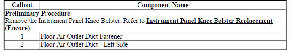
FLOOR FRONT AIR OUTLET DUCT REPLACEMENT - LEFT SIDE (Encore)
.gif)
Fig. 82: Floor Front Air Outlet Duct - Left Side (Encore)
Floor Front Air Outlet Duct Replacement - Left Side (Encore)
.jpg)
INSTRUMENT PANEL OUTER AIR OUTLET DUCT REPLACEMENT (Encore)
.gif)
Fig. 83: Instrument Panel Outer Air Outlet Duct (Encore)
Instrument Panel Outer Air Outlet Duct Replacement (Encore)

WINDSHIELD DEFROSTER OUTLET DUCT REPLACEMENT
.jpg)
Fig. 84: Windshield Defroster Outlet Duct
Windshield Defroster Outlet Duct Replacement
.jpg)

Floor rear air outlet duct replacement - left side
.gif)
Fig. 85: Floor Rear Air Outlet Duct - Left Side
Floor Rear Air Outlet Duct Replacement - Left Side

FLOOR REAR AIR OUTLET DUCT REPLACEMENT - RIGHT SIDE
.gif)
Fig. 86: Floor Rear Air Outlet Duct - Right Side
Floor Rear Air Outlet Duct Replacement - Right Side

TEMPERATURE VALVE GEAR REPLACEMENT (C60)
.gif)
Fig. 87: Temperature Valve Gear (C60)
Temperature Valve Gear Replacement (C60)

.jpg)
HEATER CORE REPLACEMENT
.gif)
Fig. 88: Heater Core
Heater Core Replacement
.jpg)
HEATER CASE REPLACEMENT
.gif)
Fig. 89: Heater Case
Heater Case Replacement
.jpg)
READ NEXT:
 Description and operation
Heating and air conditioning system description and operation
Engine Coolant
Engine coolant is the key element of the heating system. The thermostat
controls engine operating coolant
temperature. The
Diagnostic information and procedures
SCHEMATIC WIRING DIAGRAMS
HVAC WIRING SCHEMATICS (ENCORE)
Power, Ground, and Blower Motor
Fig. 1: Power, Ground, and Blower Motor
Compressor Controls
Fig. 2: Compressor Controls
Duct and Evaporato
SEE MORE:
Cylinder head replacement
Cylinder head replacement - Removal Procedure
Special Tools
EN-470-B Angular Torque Wrench
EN-955 Fixing Pin
EN-953-A Fixing Tool
For equivalent regional tools, refer to Special Tools.
Removal Procedure
Disconnect battery negative cable. Refer to Battery Negative Cable
Disconnection and Con
Diagnostic system check - vehicle
Diagnostic Instructions
Review Strategy Based Diagnosis for an overview of the diagnostic
approach.
Diagnostic System Check Instructions provides an overview of each
diagnostic step.
Continue through the Diagnostic System Check until you are directed to
follow a particular diagnostic or
r
