Buick Encore: Repair instructions - on vehicle
Transmission fluid drain and fill
Draining Procedure
NOTE:
- The fluid check bolt at the front of the transmission may not be opened.
- The transmission fluid drained out during the pre-delivery inspection may be re-used. New transmission fluid must be used during servicing work.
The transmission fluid must be brought up to operating temperature before draining.
- Raise and support the vehicle. Refer to Lifting and Jacking the Vehicle .
- Remove the front compartment front center insulator, if equipped. Refer to Front Compartment Front Center Insulator Replacement .
.gif)
Fig. 16: Transmission Fluid Drain Fastener
- Clean away all dirt and debris from the transmission fluid drain fastener area.
- Position an appropriate container under the transmission.
- Remove the transmission fluid drain fastener (1).
- Allow the transmission fluid to drain into the container.
CAUTION: Refer to Fastener Caution .
- Install a new transmission fluid drain fastener and tighten to 20 (15 lb ft).
- Remove the container used to catch the used transmission fluid from under the vehicle.
- Install the front compartment front center insulator, if equipped. Refer to Front Compartment Front Center Insulator Replacement .
Filling Procedure
.gif)
Fig. 17: Transmission Fluid Fill Fastener
- Lower the vehicle.
- Remove the engine control module with the bracket from the battery tray. Refer to Engine Control Module Replacement , for the 1.2L or 1.4L engine.
- Clean away all dirt and debris from the transmission fluid fill fastener area.
- Remove the transmission fluid fill fastener (1).
- Fill the transmission with the appropriate amount of fluid. Refer to Manual Transmission Specifications.
- Install a new transmission fluid fill fastener and tighten to 30 (22 lb ft).
- Install the engine control module with the bracket to the battery tray. Refer to Engine Control Module Replacement , for the 1.2L or 1.4L engine.
TRANSMISSION CONTROL LEVER BOOT REPLACEMENT
.gif)
Fig. 18: Transmission Control Lever Knob
Transmission Control Lever Boot Replacement
.jpg)
TRANSMISSION CONTROL LEVER KNOB REPLACEMENT
.gif)
Fig. 19: Transmission Control Lever Knob
Transmission Control Lever Knob Replacement
.jpg)
MANUAL TRANSMISSION SHIFT LEVER AND SELECTOR LEVER CABLE REPLACEMENT
Removal Procedure
- Remove the battery tray. Refer to Battery Tray Replacement .
.gif)
Fig. 20: Shift Lever And Selector Lever Cable End
- Disconnect the shift lever and selector lever cable end (1) from the transmission shift lever and selector lever.
- Pull the cable retainers (2) up while pushing the cable retainers rearward to release the shift lever and selector lever cable from the shift lever and selector lever cable bracket.
- Remove the floor console. Refer to Front Floor Console Replacement (Encore) , Front Floor Console Replacement (Encore) .
.gif)
Fig. 21: Shift Lever & Selector Lever Cable Grommet And Fasteners
- Move the floor carpet in order to get access to the shift lever and selector lever cable grommet (1).
- Remove the grommet fasteners (2).
.gif)
Fig. 22: Shift Lever And Selector Lever Cable
- Lift the adjustment locks (2) up while pushing the adjustment retainers (1) rearward, one for each cable, to release the shift lever and selector lever cable.
.gif)
Fig. 23: Transmission Control Assembly
- Squeeze the shift lever and the selector lever cable retainers (1) then lift up from the transmission control assembly (3), then remove the shift lever and selector lever cable from the shift and selector control.
- Pull the shift lever and the selector lever cable assembly through the cowl into the passenger compartment.
- Remove the shift lever and the selector lever cable assembly from the vehicle.
Installation Procedure
- Position the shift lever and the selector lever cable assembly in the vehicle.
- Gently pull the shift lever and the selector lever cable assembly through the cowl into the engine compartment.
.gif)
Fig. 24: Shift Lever And Selector Lever Cable End
- Connect the shift lever and the selector lever cable ends (1) to the transmission shift lever and the selector lever.
- Install the shift lever and the selector lever cable to the shift lever and the selector lever cable bracket.
.gif)
Fig. 25: Shift Lever & Selector Lever Cable Grommet And Fasteners
- Move the floor carpet in order to get access to the shift lever and selector lever cable grommet (1).
CAUTION: Refer to Fastener Caution .
- Install the grommet fasteners (2) and tighten to 9 (80 lb in).
.gif)
Fig. 26: Transmission Control Assembly
- Connect the shift lever and selector lever cables to the shift and selector control adjusters (2).
- Install the shift lever and selector lever cable retainers (1) to the transmission control (3).
.gif)
Fig. 27: Cable Adjustment Locks
- Press down and lock both cable adjustment locks (1), one for each cable, to lock the shift lever and selector lever cable.
- Adjust the shift lever and selector lever cables. Refer to Manual Transmission Shift Lever and Selector Lever Cable Adjustment.
- Install the floor console. Refer to Front Floor Console Replacement (Encore) , Front Floor Console Replacement (Encore) .
- Install the battery tray. Refer to Battery Tray Replacement .
- Verify correct operation of the transmission control assembly.
Selector and shift lever cable bracket replacement
Removal Procedure
- Remove the battery tray. Refer to Battery Tray Replacement .
.gif)
Fig. 28: Shift Lever And Selector Lever Cable End
- Disconnect the shift lever and selector lever cable end (1) from the transmission shift lever and selector lever.
- Pull the cable retainers (2) up while pushing the cable retainers rearward to release the shift lever and selector lever cable from the shift lever and selector lever cable bracket.
.gif)
Fig. 29: Shift Lever And Selector Lever Cable Bracket
- Remove the 2 shift lever and selector lever cable bracket fasteners (1).
- Remove the shift lever and selector lever cable bracket (2) from the transmission.
Installation Procedure
.gif)
Fig. 30: Shift Lever And Selector Lever Cable Bracket
- Position the shift lever and selector lever cable bracket (2) on the transmission.
CAUTION: Refer to Fastener Caution .
- Install the 2 shift lever and selector lever cable bracket fasteners (1) and tighten to 22 (16 lb ft).
.gif)
Fig. 31: Shift Lever And Selector Lever Cable End
- Connect the shift lever and selector lever cable ends (1) to the transmission shift lever and selector lever.
- Install the shift lever and selector lever cable retainers (2) to the shift lever and selector lever cable bracket.
- Adjust the shift lever and selector lever cables. Refer to Manual Transmission Shift Lever and Selector Lever Cable Adjustment.
- Install the battery tray. Refer to Battery Tray Replacement .
- Verify correct operation of the transmission control assembly.
TRANSMISSION CONTROL REPLACEMENT
Removal Procedure
- Remove the floor console. Refer to Front Floor Console Replacement (Encore) , Front Floor Console Replacement (Encore)
.gif)
Fig. 32: Shift Lever And Selector Lever Cable
- Lift the adjustment locks (2) up while pushing the adjustment retainers (1) rearward, one for each cable, to release the shift lever and selector lever cable.
.gif)
Fig. 33: Transmission Control Assembly
- Squeeze the shift lever and selector lever cable retainers (1) then lift up on the transmission control assembly (3).
- Remove the shift lever and selector lever cables from the shift and selector control.
.gif)
Fig. 34: Transmission Control Bolts
- Remove the 4 transmission control bolts (1).
- Remove the transmission control from the vehicle.
Installation Procedure
.gif)
Fig. 35: Transmission Control Bolts
- Position the transmission control in the vehicle.
CAUTION: Refer to Fastener Caution .
- Install the 4 transmission control bolts (1) and tighten to 9 (80 lb in).
.gif)
Fig. 36: Transmission Control Assembly
- Connect the shift lever and selector lever cables to the shift and selector control adjusters (2).
- Install the shift lever and selector lever cable retainers (1) to the transmission control (3).
.gif)
Fig. 37: Cable Adjustment Locks
- Press down and lock both cable adjustment locks (1), one for each cable, to lock the shift lever and selector lever cable.
- Adjust the shift lever and selector level cables. Refer to Manual Transmission Shift Lever and Selector Lever Cable Adjustment.
- Install the floor console. Refer to Front Floor Console Replacement (Encore) , Front Floor Console Replacement (Encore) .
- Verify the correct operation of the transmission control assembly.
MANUAL TRANSMISSION SHIFT LEVER AND SELECTOR LEVER CABLE ADJUSTMENT
- Remove the floor console. Refer to Front Floor Console Replacement (Encore) , Front Floor Console Replacement (Encore) .
.gif)
Fig. 38: Shift Lever And Selector Lever Cable
- Lift the adjustments locks (2) up while pushing the adjustment retainers (1) rearward, one for each cable, to release the shift lever and selector lever cable.
.gif)
Fig. 39: Selector Lever
- Block the shift control housing, push the selector lever (2) backwards and push (arrow) the blocking device (1) towards the shift control housing.
.gif)
Fig. 40: Transmission Gear Control
NOTE: The hole of the transmission gear control (2) must be aligned to the hole in the base so the pin (1) can pass through both. The transmission gear control will be locked in the 1-2 neutral position.
- Lock the position of the shift control lever by rotating the lockout device with the following instructions:
- Push down on tab (1) and pull up on device (2) to release from installed position.
- Turn the device 90 degrees in a clockwise direction.
- Secure integral pins (4) in holes located on shifter base by pushing down device (2).
- Secure adjuster locks (3) by pushing down until locked. One for each cable.
NOTE: During this procedure DO NOT touch or preload the fixed shift lever as this may cause mis-adjustment to the shift system.
- Reposition the lockout device with the following instructions:
- Push down on tab (1) and pull up on device (2) to release from installed position.
- Turn the device (2) 90 degrees in a counterclockwise direction.
- Push downward on the reverse lockout device (2) until tab (1) snaps into detent.
.gif)
Fig. 41: Blocking Device
NOTE: When unblocking the blocking device (1) a defined snap noise should be audible, a snap effect should be felt.
- Unblock the shift control housing, push slightly the selector lever (2) backwards and pull (arrow) the blocking device away from the shift control housing.
- Install the floor console. Refer to Front Floor Console Replacement (Encore) , Front Floor Console Replacement (Encore) .
- Verify correct operation of the transmission control assembly.
Backup lamp switch replacement
.gif)
Fig. 42: Backup Lamp Switch
Backup Lamp Switch Replacement
.jpg)
TRANSMISSION REAR MOUNT REPLACEMENT (AWD)
Removal Procedure
- Remove the transfer case. Refer to Transfer Case Replacement .
.gif)
Fig. 43: Transmission Bracket Bolts
- Remove and DISCARD the five transmission bracket bolts (1).
.gif)
Fig. 44: Transmission Bracket
- Remove and DISCARD the transmission rear mount through bolt (1).
- Remove the transmission bracket (2) from the transmission.
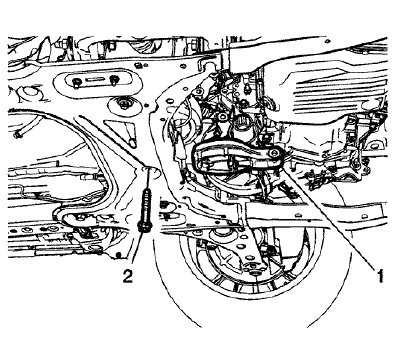
Fig. 45: Transmission Rear Mount
- Remove and DISCARD the transmission rear mount fastener (2).
- Remove the transmission rear mount (1) from the vehicle.
Installation Procedure
.gif)
Fig. 46: Transmission Rear Mount
- Install the transmission rear mount (1) to the vehicle.

Fig. 47: Transmission Bracket
- Install the transmission bracket (2) to the transmission.
.gif)
Fig. 48: Transmission Bracket Bolts
CAUTION: Refer to Fastener Caution .
- Install the NEW transmission bracket to transmission bolts (1) and tighten to 100 (74 lb ft) plus 30-40 degrees.
.gif)
Fig. 49: Transmission Rear Mount
- Install the NEW transmission rear mount fastener (2) and tighten to 100 (74 lb ft) plus 90-105 degrees.

Fig. 50: Transmission Bracket
- Install the NEW transmission rear mount through bolt (1) and tighten to 80 (59 lb ft) plus 45-60 degrees.
- Install the transfer case. Refer to Transfer Case Replacement .
TRANSMISSION REAR MOUNT REPLACEMENT (FWD)
Removal Procedure
- Raise and support the vehicle. Refer to Lifting and Jacking the Vehicle .
- Remove the exhaust front pipe. Refer to Exhaust Front Pipe Replacement (LUV) , Exhaust Front Pipe Replacement .
- Using a suitable jack stand, support the rear of the powertrain.
.gif)
Fig. 51: Transmission Rear Mount Bracket Through Bolt
- Remove and DISCARD the transmission rear mount to bracket through bolt (1).
- Remove and DISCARD the transmission rear mount bolt (2).
.gif)
Fig. 52: Transmission Rear Mount Bracket And Bolts
- Remove and DISCARD the transmission rear mount bracket fasteners (1).
- Remove the transmission rear mount and the transmission rear mount bracket.
Installation Procedure

Fig. 53: Transmission Rear Mount Bracket And Bolts
- Install the transmission rear mount and the transmission rear mount bracket.
CAUTION: Refer to Fastener Caution .
- Install the NEW transmission rear mount bracket fasteners (1) and tighten to 100 (74 lb ft) plus 30-45 degrees.
.gif)
Fig. 54: Transmission Rear Mount Bracket Through Bolt
- Install the NEW transmission rear mount bolt (2) and tighten to 100 (74 lb ft) plus 90 - 105 degrees.
- Install the NEW transmission rear mount to bracket through bolt (1) and tighten to 80 (59 lb ft) plus 45- 60 degrees.
- Remove the jack stand.
- Install the exhaust front pipe. Refer to Exhaust Front Pipe Replacement (LUV) , Exhaust Front Pipe Replacement .
- Lower the vehicle.
TRANSMISSION MOUNT REPLACEMENT - LEFT SIDE
Removal Procedure
- Remove the battery tray. Refer to Battery Tray Replacement .
- Install the engine support fixture. Refer to Engine Support Fixture .
.gif)
Fig. 55: Left Transmission Mount
- Remove and DISCARD the left transmission mount to bracket bolts (1).
- Remove the left transmission mount to body bolts (2).
- Remove the left transmission mount to body nut (3).
- Remove the left transmission mount (4) from the vehicle.
Installation Procedure

Fig. 56: Left Transmission Mount
- Install the left transmission mount (4) to the vehicle.
CAUTION: Refer to Fastener Caution .
- Install the left transmission mount to body bolts (2) and tighten to 58 (43 lb ft).
- Install the left transmission mount to body nut (3) and tighten to 58 (43 lb ft).
- Install the NEW left transmission mount to transmission bolts (1) and tighten to 50 (37 lb ft) plus 60-75 degrees.
- Remove the engine support fixture. Refer to Engine Support Fixture
- Install the battery tray. Refer to Battery Tray Replacement .
TRANSMISSION MOUNT BRACKET REPLACEMENT - REAR (AWD)
Removal Procedure
- Remove the transfer case. Refer to Transfer Case Replacement .
.gif)
Fig. 57: Transmission Bracket Bolts
- Remove and DISCARD the five transmission bracket bolts (1).
.gif)
Fig. 58: Transmission Bracket
- Remove and DISCARD the transmission rear mount through bolt (1).
- Remove the transmission bracket (2) from the transmission.
Installation Procedure
.gif)
Fig. 59: Transmission Bracket
- Install the transmission bracket (2) to the transmission.
.gif)
Fig. 60: Transmission Bracket Bolts
CAUTION: Refer to Fastener Caution .
- Install the NEW transmission bracket to transmission bolts (1) and tighten to 100 (74 lb ft) plus 30-40 degrees.
.gif)
Fig. 61: Transmission Bracket
- Install the NEW transmission rear mount through bolt (1) and tighten to 80 (59 lb ft) plus 45-60 degrees.
- Install the transfer case. Refer to Transfer Case Replacement .
Transmission mount bracket replacement - Rear (FWD)
Removal Procedure
- Raise and support the vehicle. Refer to Lifting and Jacking the Vehicle .
- Remove the exhaust front pipe. Refer to Exhaust Front Pipe Replacement (LUV) , Exhaust Front Pipe Replacement .
- Using a suitable jack stand, support the rear of the powertrain.
.gif)
Fig. 62: Transmission Rear Mount Bracket Through Bolt
- Remove and DISCARD the transmission rear mount to bracket through fastener (1).
- Remove and DISCARD the transmission rear mount fastener (2).
.gif)
Fig. 63: Transmission Rear Mount Bracket And Bolts
- Remove and DISCARD the transmission rear mount bracket fasteners (1).
- Remove the transmission rear mount and mount bracket.
Installation Procedure
.gif)
Fig. 64: Transmission Rear Mount Bracket And Bolts
- Install the transmission rear mount and mount bracket.
CAUTION: Refer to Fastener Caution .
- Install the NEW transmission rear mount bracket fasteners (1) and tighten to 100 (74 lb ft) plus 30-45 degrees.
.gif)
Fig. 65: Transmission Rear Mount Bracket Through Bolt
- Install the NEW transmission rear mount fastener (2) and tighten to 100 (74 lb ft) plus 90 - 105 degrees.
- Install the NEW transmission rear mount to bracket through fastener (1) and tighten to 80 (59 lb ft) plus 45-60 degrees.
- Remove the jack stand.
- Install the exhaust front pipe. Refer to Exhaust Front Pipe Replacement (LUV) , Exhaust Front Pipe Replacement .
- Lower the vehicle.
TRANSMISSION MOUNT BRACKET REPLACEMENT - LEFT SIDE
Removal Procedure
- Remove the battery tray from the vehicle. Refer to Battery Tray Replacement .
- Remove the power brake booster pump assembly from left
transmission mount bracket, if equipped.
Refer to Power Brake Booster Pump Replacement .
- Remove the left transmission mount. Refer to Transmission Mount Replacement - Left Side.
.gif)
Fig. 66: Transmission Mount Bracket & Bolts
- Remove the 3 left transmission mount bracket to transmission bolts (1).
- Remove the left transmission mount bracket (2) from the transmission.
Installation Procedure
.gif)
Fig. 67: Transmission Mount Bracket & Bolts
- Install the left transmission mount bracket (2) to the transmission.
CAUTION: Refer to Fastener Caution
- Install the left transmission mount bracket to transmission bolts (1) and tighten to 100 (74 lb ft).
- Install the left transmission mount. Refer to Transmission Mount Replacement - Left Side.
- Install the power brake booster pump assembly to left transmission mount bracket, if equipped. Refer to Power Brake Booster Pump Replacement .
- Install the battery tray to the vehicle. Refer to Battery Tray Replacement .
FRONT WHEEL DRIVE SHAFT SEAL REPLACEMENT - LEFT SIDE
Special Tools
- CH-466-A Gear, Bearing Remover/Installer
- DT-519 Installer Drift
- DT-523 Remover/Installer
For equivalent regional tools, refer to Special Tools.
Removal Procedure
- Remove the left front wheel drive shaft. Refer to Front Wheel Drive Shaft Replacement - Left Side .
.gif)
Fig. 68: Front Differential Carrier Flange, Bolts And Washers
- Remove and DISCARD the 4 front differential carrier flange bolts (3) and 4 washers (2).
- Remove the front differential carrier flange (1) from the transmission
.gif)
Fig. 69: Front Wheel Drive Shaft Oil Seal, Front Differential Carrier Flange
And Remover/Installer
- Remove and DISCARD the front wheel drive shaft oil seal (1) from front differential carrier flange (2).
- Put front differential carrier flange on CH-466-A gear, bearing remover/installer (5) and press front wheel drive shaft oil seal out of front differential carrier flange using DT-523-1 remover/installer (3) in conjunction with DT-523-3 remover/installer (4).
.gif)
Fig. 70: Front Differential Carrier Flange And Seal
- Remove and DISCARD the front differential carrier flange seal (2) from front differential carrier flange (1).
Installation Procedure
.gif)
Fig. 71: Front Differential Carrier Flange And Seal
NOTE: Coat the front differential carrier flange seal with NEW transmission fluid.
- Install the NEW front differential carrier flange seal (2) to front differential carrier flange (1).
.gif)
Fig. 72: Front Differential Carrier Flange, Front Wheel Drive Shaft Oil Seal
And Installer Drift Courtesy of GENERAL MOTORS COMPANY
NOTE: Coat the front wheel drive shaft oil seal with NEW transmission fluid.
- Install the NEW front wheel drive shaft oil seal (1) to front differential carrier flange (2) using DT-519 installer drift (3).
.gif)
Fig. 73: Front Differential Carrier Flange, Bolts And Washers
- Install the front differential carrier flange (1) to transmission.
CAUTION: Refer to Fastener Caution .
CAUTION: Refer to Torque-to-Yield Fastener Caution .
- Install the 4 washers (2) and 4 NEW front differential carrier flange bolts (3) and tighten to 20 (15 lb ft) plus 45 degrees.
- Install the left front wheel drive shaft. Refer to Front Wheel Drive Shaft Replacement - Left Side .
Front wheel drive shaft seal replacement - right side
Removal Procedure
- Remove the transfer case. Refer to Transfer Case Replacement .
.gif)
Fig. 74: Transfer Case-To-Transfer Case Bracket Seal
- Remove and discard the transfer case-to-transfer case bracket seal (1).
Installation Procedure
.gif)
Fig. 75: Transfer Case-To-Transfer Case Bracket Seal
- Clean the contact surfaces between the transfer case and the transfer case bracket.
NOTE: Install the OD groove of the seal onto the raised area in the adapter seal bore. A properly installed seal will be installed 2.66 mm (0.10 in) below the machined surface when measured from the bushing alignment mark side of the adapter.
- Install a new transfer case-to-transfer case bracket seal (1). Refer to Transfer Case Identification .
- Install the transfer case. Refer to Transfer Case Replacement .
Front wheel drive shaft seal replacement - right side (FWD)
.gif)
Fig. 76: Front Wheel Drive Shaft Seal - Right Side (FWD)
Front Wheel Drive Shaft Seal Replacement - Right Side (FWD)
.jpg)
.jpg)
TRANSMISSION REPLACEMENT
Removal Procedure
- Remove the battery and battery tray. Refer to Battery Tray Replacement .
- Remove front bumper fascia opening upper cover. Refer to Front Bumper Fascia Opening Upper Cover Replacement .
- Without draining the coolant or removing the hoses, remove and position
aside the radiator surge tank.
Refer to Radiator Surge Tank Replacement (LUV, 2H0, LUJ) .
- Remove the power brake booster pump assembly from left transmission
mount bracket, if equipped.
Refer to Power Brake Booster Pump Bracket Replacement .
.gif)
Fig. 77: Shift Lever And Selector Lever Cable End
- Disconnect the shift lever and selector lever cable ends (1) from the transmission shift lever and selector lever.
- Pull the cable retainers (2) up while pushing the cable retainers rearward to release the shift lever and selector lever cable from the shift lever and selector lever cable bracket.
- Disconnect the wiring harness clips from the transmission.
- Disconnect the electrical connector from the neutral position sensor.
.gif)
Fig. 78: Clutch Actuator Cylinder Front Pipe And Retainer
NOTE: Before disconnecting the clutch actuator cylinder front pipe, remove the clutch/brake fluid from the reservoir tank.
- Remove the clutch actuator cylinder front pipe retaining clip (1).
- Disconnect the clutch actuator cylinder front pipe (2) from the clutch actuator cylinder pipe elbow.
.gif)
79: Backup Lamp Switch Electrical Connector
- Disconnect the electrical connector (1) from the backup lamp switch.
.gif)
Fig. 80: Upper Transmission Bolts
- Remove the 3 transmission upper bolts (1) from the transmission.
- Support the CRFM from the top.
- Install the engine support fixture. Refer to Engine Support Fixture .
- Remove the exhaust front pipe. Refer to Exhaust Front Pipe Replacement (LUV) , Exhaust Front Pipe Replacement .
- On AWD vehicles, remove the propeller shaft. Refer to Two-Piece Propeller Shaft Replacement .
- Remove the drivetrain and front suspension frame. Refer to Drivetrain and Front Suspension Frame Replacement (Long Cradle) , Drivetrain and Front Suspension Frame Replacement (Short Cradle) .
- Drain the transmission fluid. Refer to Transmission Fluid Drain and Fill.

Fig. 81: Wheel Drive Shaft
- Remove the both front wheel drive shafts (1) from the transmission. Refer to Front Wheel Drive Shaft Replacement - Left Side , and Front Wheel Drive Shaft Replacement - Right Side .
- On FWD vehicles, remove the intermediate shaft. Refer to Front Wheel Drive Intermediate Shaft Replacement (LUV with MH8 or MH5) .
- On AWD vehicles, remove the transfer case. Refer to Transfer Case Replacement .
- Remove the transmission rear mount bracket. Refer to Transmission Mount Bracket Replacement - Rear (FWD), Transmission Mount Bracket Replacement - Rear (AWD).
.gif)
Fig. 82: Left Transmission Mount
- Remove the left transmission mount. Refer to Transmission Mount Replacement - Left Side.
- Remove the left transmission mount bracket (4). Refer to Transmission Mount Bracket Replacement - Left Side.
- Support the transmission with a suitable jack.
.gif)
Fig. 83: Lower Transmission Bolts
- Remove the lower transmission bolts (1).
- Remove the lower transmission bolt and nut (2).
- On FWD vehicles, remove the transmission side cover (3).
- Separate the transmission from the engine.
- Lower the transmission with the transmission jack far enough to remove the transmission.
Installation Procedure
WARNING: Use care when cleaning the clutch hub. The clutch hub may have sharp edges and can cause personal injury if contact is made. Wear protective gloves to avoid personal injury.
- Clean the clutch hub and the input shaft from any debris and contaminates with a lint-free towel.
.gif)
Fig. 84: Using Flat Brush To Apply Light Coating Of Multi-Purpose Grease
CAUTION: Applying too much or the wrong type of grease on the transmission input shaft may cause damage, clutch slippage or failure. Always apply the correct type of grease. Never apply more grease than is necessary to coat the transmission input shaft with a very thin film of grease.
- Use a clean flat brush (1) to apply very light coating of multi-purpose grease to input shaft until the metal is only shiny. No visible clumps of grease are permissible regardless of size. Smear away from the transmission in direction of the shown arrow.
.gif)
Fig. 85: Lint Free Towel
CAUTION: Ensure that no grease remains on the lead surface of the transmission input shaft. Clean the lead surface of the transmission input shaft prior to the assembly of the transmission to the engine.
Failure to maintain a clean surface may cause clutch slippage or failure.
- Clean the entire lead surface of the input shaft with a NEW, lint-free towel (1).
- Raise the transmission with the transmission jack and position the transmission to the engine.
.gif)
Fig. 86: Lower Transmission Bolts
- On FWD vehicles, install the transmission side cover (3).
CAUTION: Refer to Fastener Caution .
- Install the lower transmission bolts (1) and tighten to 58 (43 lb ft).
- Install the lower transmission bolt and nut (2) and tighten to 58 (43 lb ft).
- Remove the transmission jack.
.gif)
Fig. 87: Left Transmission Mount
- Install the left transmission mount bracket (4). Refer to Transmission Mount Bracket Replacement - Left Side.
- Install the left transmission mount. Refer to Transmission Mount Replacement - Left Side.
- Install the transmission rear mount bracket. Refer to Transmission Mount Bracket Replacement - Rear (FWD), Transmission Mount Bracket Replacement - Rear (AWD).
- On AWD vehicles, install the transfer case. Refer to Transfer Case Replacement .
- On FWD vehicles, install the intermediate shaft. Refer to Front Wheel Drive Intermediate Shaft Replacement (LUV with MH8 or MH5) .
.gif)
Fig. 88: Wheel Drive Shaft
- Install both front wheel drive shafts (1) to the transmission. Refer to Front Wheel Drive Shaft Replacement - Left Side , and Front Wheel Drive Shaft Replacement - Right Side .
- Install the drivetrain and front suspension frame. Refer to Drivetrain and Front Suspension Frame Replacement (Long Cradle) , Drivetrain and Front Suspension Frame Replacement (Short Cradle) .
- On AWD vehicles, install the propeller shaft. Refer to Two-Piece Propeller Shaft Replacement .
- Install the exhaust front pipe. Refer to Exhaust Front Pipe Replacement (LUV) , Exhaust Front Pipe Replacement .
- Remove the engine support fixture. Refer to Engine Support Fixture .
.gif)
Fig. 89: Upper Transmission Bolts
- Install the upper transmission bolts (1) and tighten to 58 (43 lb ft).
.gif)
Fig. 90: Backup Lamp Switch Electrical Connector
- Connect the electrical connector (1) to the backup lamp switch.
.gif)
Fig. 91: Clutch Actuator Cylinder Front Pipe And Retainer
- Connect the clutch actuator cylinder front pipe (2) to the clutch actuator cylinder pipe elbow.
- Install the clutch actuator front pipe clip (1).
- Connect the electrical connector to the neutral position sensor.
- Connect the wire harness clips to the transmission.
.gif)
Fig. 92: Shift Lever And Selector Lever Cable End
- Install the shift lever and selector lever cable (2) to the shift lever and selector lever cable bracket.
- Connect the transmission range selector lever cable terminals (1) to the transmission manual pins.
- Adjust the shift lever and selector lever cables. Refer to Manual Transmission Shift Lever and Selector Lever Cable Adjustment.
- Bleed the clutch hydraulic system. Refer to Hydraulic Clutch System Bleeding .
- Fill the transmission fluid. Refer to Transmission Fluid Drain and Fill.
- Install the power brake booster pump assembly to left transmission mount bracket, if equipped. Refer to Power Brake Booster Pump Bracket Replacement .
- Install the radiator surge tank. Refer to Radiator Surge Tank Replacement (LUV, 2H0, LUJ) .
- Install front bumper fascia opening upper cover. Refer to Front Bumper Fascia Opening Upper Cover Replacement .
- Install the battery and battery tray. Refer to Battery Tray Replacement .
READ NEXT:
 Description and operation
TRANSMISSION SYSTEM DESCRIPTION AND OPERATION
The M32-6 is a 6-speed manual transmission. This manual transmission is an
all-synchromesh 3-shaft
transmission.
Fig. 93: 3 Shaft Transmission
This 3-s
Clutch
SPECIFICATIONS
FASTENER TIGHTENING SPECIFICATIONS
Fastener Tightening Specifications
GENERAL SPECIFICATIONS
General Specifications
DIAGNOSTIC INFORMATION AND PROCEDURES
SYMPTOMS - CLUTCH
Symptom
Repair instructions
CLUTCH PEDAL REPLACEMENT
NOTE: The clutch pedal is part of the brake, accelerator, and
clutch pedal assembly
and cannot be serviced separately.
To replace the brake, accelerator and clutch pedal asse
SEE MORE:
Oil pump
NOTE:
Examples used in this article are general in nature and do not necessarily
relate
to a specific engine or system. Illustrations and procedures have been chosen
to guide mechanic through engine overhaul process. Descriptions of processes
of cleaning, inspection, assembly and machine shop pract
Antilock Brake System (ABS)
The Antilock Brake System (ABS)
helps prevent a braking skid and
maintain steering while
braking hard.
ABS performs a system check when
the vehicle is first driven.
A momentary motor or clicking noise
may be heard while this test is going
on, and the brake pedal may move
slightly. This is normal.
