Buick Encore: Supplemental Inflatable Restraints - Repair instructions
Sir service precautions
General Service Instructions
WARNING: When performing service on or near the SIR components or the SIR wiring, the SIR system must be disabled. Refer to SIR Disabling and Enabling . Failure to observe the correct procedure could cause deployment of the SIR components, personal injury, or unnecessary SIR system repairs.
NOTE: The Inflatable Restraint Sensing and Diagnostic Module (SDM) maintains a reserved energy supply. The reserved energy supply provides deployment power for the SIR air bags. Deployment power may be available for up to 2 minutes after disconnecting the vehicle power. Disabling the SIR system prevents deployment of the SIR air bags from the reserved energy supply.
NOTE: The following are general service instructions which must be followed in order to properly repair the vehicle and return it to its original integrity:
- Do not expose air bags to temperatures above 85 ºC (185 ºF)
- Verify the correct replacement part number. Do not substitute a component from a different vehicle
- Use only original GM replacement parts available from your authorized GM dealer. Do not use salvaged parts for repairs to the SIR system
NOTE: Discard any of the following components if it has been dropped from a height of 80 cm (15.75 in) or greater:
- Inflatable Restraint Sensing and Diagnostic Module
- Passenger instrument panel air bag
- Driver steering wheel air bag
- Driver steering wheel air bag coil
- Roof rail air bags
- Front and /or side impact sensors
- Seat belt achor and/or retractor pretensioners
- Front seat side air bag
- Knee air bag
INFLATABLE RESTRAINT REMOTE IMPACT SENSOR REPLACEMENT
Fig. 10: Inflatable Restraint Remote Impact Sensor
Inflatable Restraint Remote Impact Sensor Replacement


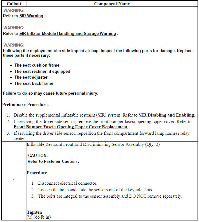
FRONT END INFLATABLE RESTRAINT DISCRIMINATING SENSOR REPLACEMENT (Encore)
Fig. 11: Front End Inflatable Restraint Discriminating Sensor
Front End Inflatable Restraint Discriminating Sensor Replacement (Encore)
FRONT END INFLATABLE RESTRAINT DISCRIMINATING SENSOR REPLACEMENT(ENCORE)
Fig. 12: Front End Inflatable Restraint Discriminating Sensor Replacement
(Encore)
Front End Inflatable Restraint Discriminating Sensor Replacement (Encore)

AIRBAG SIDE IMPACT SENSOR REPLACEMENT (ENCORE)

Fig. 13: Airbag Side Impact Sensor (Encore)
Airbag Side Impact Sensor Replacement (Encore)
.jpg)
AIRBAG SIDE IMPACT SENSOR REPLACEMENT (Encore)

Fig. 14: Airbag Side Impact Sensor
Airbag Side Impact Sensor Replacement (Encore)
.jpg)
.jpg)
AIRBAG SENSING AND DIAGNOSTIC MODULE REPLACEMENT (ENCORE)
Fig. 15: Airbag Sensing and Diagnostic Module (Encore)
Airbag Sensing and Diagnostic Module Replacement (Encore)
.jpg)
AIRBAG SENSING AND DIAGNOSTIC MODULE REPLACEMENT (Encore)
Fig. 16: Airbag Sensing and Diagnostic Module
Airbag Sensing and Diagnostic Module Replacement (Encore)
.jpg)
.jpg)
STEERING WHEEL AIRBAG REPLACEMENT (ENCORE)
.gif)
Fig. 17: Steering Wheel Airbag (Encore)
Steering Wheel Airbag Replacement (Encore)
.jpg)
.jpg)
STEERING WHEEL AIRBAG REPLACEMENT (Encore)
Fig. 18: Steering Wheel Airbag
Steering Wheel Airbag Replacement (Encore)
.jpg)
STEERING WHEEL AIRBAG COIL REPLACEMENT (Encore)

Fig. 19: Steering Wheel Airbag Coil
Steering Wheel Airbag Coil Replacement (Encore)
.jpg)
STEERING WHEEL AIRBAG COIL REPLACEMENT (ENCORE)

Fig. 20: Steering Wheel Airbag Coil (Encore)
Steering Wheel Airbag Coil Replacement (Encore)
.jpg)
.jpg)
AIRBAG STEERING WHEEL MODULE COIL CENTERING

Fig. 21: Steering Shaft Centering Mark
CAUTION: The new SIR coil assembly will be centered. Improper alignment of the SIR coil assembly may damage the unit, causing an inflatable restraint malfunction.
- Verify the following conditions before centering the steering wheel inflatable restraint module coil:
- The wheels on the vehicle are straight ahead.
- The centering mark (1) of the steering shaft is in the 6 o'clock position
- Turn the lobe of the coil clockwise until the coil ribbon stops. Do not force.
- Turn the lobe of the coil counterclockwise approximately 3 turns to the Neutral position.
AIRBAG INSTRUMENT PANEL MODULE REPLACEMENT

Fig. 22: Airbag Instrument Panel Module
Airbag Instrument Panel Module Replacement


INSTRUMENT PANEL LOWER AIRBAG REPLACEMENT - DRIVER SIDE (AYF)

Fig. 23: Instrument Panel Lower Airbag - Driver Side
Instrument Panel Lower Airbag Replacement - Driver Side (AYF)

.jpg)
INSTRUMENT PANEL LOWER AIRBAG REPLACEMENT - PASSENGER SIDE (AYF)

Fig. 24: Instrument Panel Lower Airbag - Passenger Side
Instrument Panel Lower Airbag Replacement - Passenger Side (AYF)
.jpg)
.jpg)
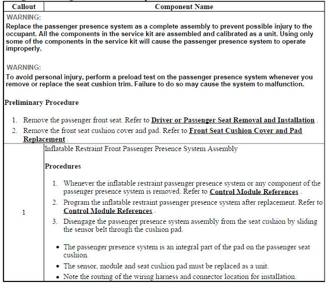
AIRBAG FRONT PASSENGER PRESENCE SENSOR REPLACEMENT
Fig. 25: Airbag Front Passenger Presence Sensor
Airbag Front Passenger Presence Sensor Replacement
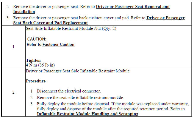
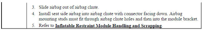
FRONT SEAT OUTBOARD SEAT BACK AIRBAG REPLACEMENT

Fig. 26: Driver or Passenger Seat Side Inflatable Restraint Module & Nuts
Front Seat Outboard Seat Back Airbag Replacement

REAR SEAT BOLSTER AIRBAG REPLACEMENT (AYF)

Fig. 27: Rear Seat Bolster Airbag
Rear Seat Bolster Airbag Replacement (AYF)

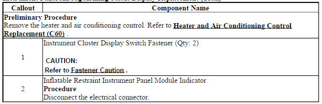
INSTRUMENT PANEL AIRBAG ARMING STATUS DISPLAY REPLACEMENT (Encore)

Fig. 28: Instrument Panel Airbag Arming Status Display
Instrument Panel Airbag Arming Status Display Replacement (Encore)
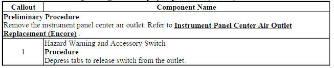
INSTRUMENT PANEL AIRBAG ARMING STATUS DISPLAY REPLACEMENT (ENCORE)
Fig. 29: Instrument Panel Airbag Arming Status Display
Instrument Panel Airbag Arming Status Display Replacement (Encore)
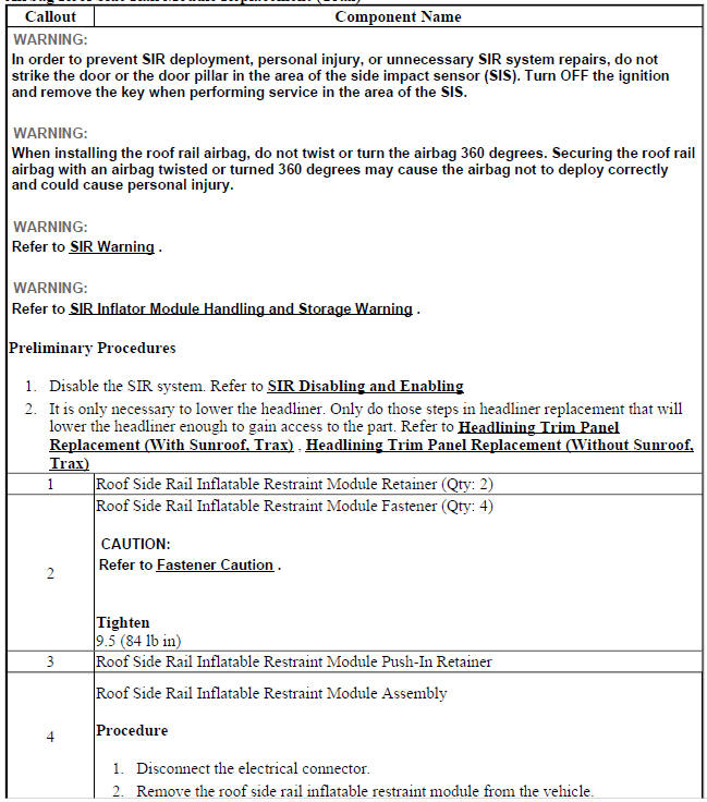
AIRBAG ROOF SIDE RAIL MODULE REPLACEMENT (ENCORE)

Fig. 30: Airbag Roof Side Rail Module
Airbag Roof Side Rail Module Replacement (Encore)


AIRBAG ROOF SIDE RAIL MODULE REPLACEMENT (Encore)
Fig. 31: Airbag Roof Side Rail Module
Airbag Roof Side Rail Module Replacement (Encore)

FRONT SEAT BELT RETRACTOR REPLACEMENT (WITH A69)

Fig. 32: Front Seat Belt Retractor (With A69)
Front Seat Belt Retractor Replacement (With A69)


FRONT SEAT BELT ANCHOR PLATE TENSIONER REPLACEMENT

Fig. 33: Front Seat Belt Anchor Plate Tensioner
Front Seat Belt Anchor Plate Tensioner Replacement


Repairs and inspections required after a collision
Accident With or Without Air Bag Deployment - Component Inspections
WARNING: Proper operation of the Supplemental Inflatable Restraint (SIR) sensing system requires that any repairs to the vehicle structure return the vehicle structure to the original production configuration. Not properly repairing the vehicle structure could cause non-deployment of the air bag (s) in a frontal collision or deployment of the air bag(s) for conditions less severe than intended.
After any collision, inspect the following components as indicated. If you detect any damage, replace the component. If you detect any damage to the mounting points or mounting hardware, repair the component or replace the hardware as needed.
- The steering column-Inspect the steering column for bending, twisting, buckling or any type of damage.
- The instrument panel knee bolsters and mounting points-Inspect the knee bolsters for bending, twisting, buckling, or any other type of damage.
- The instrument panel brackets, braces, etc.-Inspect for bending, twisting, buckling, or any other type of damage.
- The seat belts-Perform the seat belt operational and functional checks. Refer to Repairs and Inspections Required After a Collision .
- The instrument panel cross car beam-Inspect for bending, twisting, buckling, or any other type of damage.
- The instrument panel mounting points and brackets-Inspect for bending, twisting, buckling, or any other type of damage.
- The seats and seat mounting points-Inspect for bending, twisting, buckling, or any other type of damage.
- The roof and headliner mounting points.
- The brake pedal --Inspect the brake pedal for bending, twisting, buckling or any type of damage.
Accident With Frontal Air Bag Deployment - Component Replacement and Inspections
After a collision involving air bag deployment, replace the following components.
- Driver Steering Wheel Air Bag
- Passenger instrument panel air bag, if deployed
- Inflatable Restraint Sensing and Diagnostic Module (SDM), if the Inflatable Restraint Sensing and Diagnostic Module has set DTC B0052 and will not clear
- Front and/or Side Impact Sensors
- Driver/Passenger Seat Side Air Bag, if deployed
- Seat back cover if Side Seat Air Bag is deployed
- Driver/Passenger Seat Belt Anchor and/or Retractor Pretensioners
Perform additional inspections on the following components.
- Steering wheel air bag coil and the coil wiring pigtail-Inspect for melting, scorching, or other damage due to excessive heat.
- Mounting points or mounting hardware for the passenger instrument panel air bag, steering wheel air bag, Inflatable Restraint Sensing and Diagnostic Module, seat side air bag (if deployed) and seat belt anchor and/or retractor pretensioners-Inspect for any damage and repair or replace each component as needed
Accident With Side Seat Air Bag Deployment - Component Replacement and Inspections
After a collision involving driver/passenger side seat air bag deployment, replace the following components
- Left/right side impact sensors on the side of the impact.
- Left/right roof rail air bag on the side of the impact.
- Inflatable Restraint Sensing and Diagnostic Module (SDM), if the Inflatable Restraint Sensing and Diagnostic Module has set DTC B0052 and will not clear.
- Inflatable Restraint Seat Belt Anchor and/or Retractor Pretensioner.
- Driver or passenger seat back cushion cover replacement.
WARNING: Do not repair or replace the seat stitching or seams in the seat back trim cover with an internal mounted seat side airbag module. Replace the complete seat back trim cover from the OEM. Non-OEM seat stitching may cause improper airbag deployment which could result in personal injury.
Perform additional inspections on the following components.
- Mounting points or mounting hardware for the side impact sensors, and driver/passenger side seat air bags on the side of impact-Inspect for any damage and repair or replace each component as needed.
- Mounting points, mounting hardware, headliner and trim pieces for the left/right roof rail air bag on the side of impact-Inspect for any damage and repair or replace each component as needed.
- Mounting points or mounting hardware for the Inflatable Restraint Sensing and Diagnostic Module and seat belt anchor and/or retractor pretensioners-Inspect for any damage and repair or replace each component as needed.
- The seat cushion frame
- The seat recliner and cover, if equipped
- The seat adjuster
- The seat back frame
- Door trim assembly
- Impacted seat cushion side covers and switches
Accident With Seat Belt Pretensioner Deployment Only - Component Replacement and Inspections
After a collision involving driver/passenger Seat Belt Retractor or Anchor Pretensioner deployment, replace the following components.
- Driver and Passenger Inflatable restraint seat belt anchor pretensioner and/or retractor pretensioner
- Inflatable Restraint Sensing and Diagnostic Module (SDM), if the Inflatable Restraint Sensing and Diagnostic Module has set DTC B0052 and will not clear
Perform additional inspections for any damage and repair or replace each component as needed on the following components.
- Mounting points or mounting hardware for the Inflatable Restraint Sensing and Diagnostic Module
- Mounting points or mounting hardware for the Seat Belt Anchor Pretensioners
- Mounting points or mounting hardware for the Seat Belt Retractor Pretensioners
Impact Sensor Replacement Guidelines
The impact sensor replacement policy requires replacing sensors in the area of the accident damage. The area of accident damage is defined as the portion of the vehicle which is crushed, bent, or damaged due to a collision.
An example of this would be a moderate collision where the front of the vehicle impacts a object. If the vehicle has an impact sensor mounted forward of the radiator, it must be replaced.
- Replace the impact sensor whether or not the air bags have deployed.
- Replace the impact sensor even if it appears to be undamaged.
Impact sensor damage which is not visible, such as slight bending of the mounting bracket or cuts in the wire insulation, can cause improper operation of the SIR system. Do not try to determine whether the impact sensor is undamaged, replace the impact sensor. Also, if you follow a diagnostic trouble code (DTC) procedure and a malfunctioning impact sensor is indicated, replace the impact sensor.
Inflatable restraint module handling and scrapping
Special Tools
EL-38826 SIR Deployment Harness
For equivalent regional tools, refer to Special Tools.
Live and Undeployed Air Bag
WARNING: Refer to SIR Inflator Module Handling and Storage Warning
Take special care when handling or storing an undeployed air bag. An air bag deployment produces a rapid generation of gas. This may cause the air bag, or an object in front of the air bag, to project through the air in the event of an unlikely deployment.
Dual Stage Air Bags
Dual stage air bags have two deployment stages. If stage 1 was used to deploy a dual stage air bag, stage 2 may still be active. Therefore, a deployed dual stage air bag must be treated as an active air bag. If disposal of a dual stage air bag is required, both deployment loops must be energized to deploy the air bag.
Scrapping Procedure
At the end of a vehicle's useful life, certain situations may arise which will require the disposal of a live and undeployed air bag. Do NOT dispose a live and undeployed air bag through normal disposal channels until the air bag has been deployed.
Do not deploy the air bag in the following situations:
- After replacement of an air bag under warranty-the air bag may need to be returned undeployed to the manufacturer.
- If the vehicle is the subject of a product liability claim, related to the SIR system and is subject to a preliminary investigation - do NOT alter the SIR system in any manner.
- If the vehicle is involved in a campaign affecting the air bags - follow the instructions in the campaign service bulletin for proper SIR handling procedures.
Deployment Procedures
NOTE: Some countries, states or localities may not allow service deployment of air bags without special permission or training. Local laws regarding deploying and scrapping of air bags/devices with pyrotechnics must be followed.
You can only deploy the air bag inside of the vehicle.
Deployment Inside Vehicle - Vehicle Scrapping Procedure
Deploy the air bags inside of the vehicle when destroying the vehicle or when salvaging the vehicle for parts.
This includes, but is not limited to, the following situations:
- The vehicle has completed all useful life.
- Irreparable damage occurred to the vehicle in a non-deployment type accident.
- Irreparable damage occurred to the vehicle during a theft.
- The vehicle is being salvaged for parts to be used on a vehicle with a different VIN, as opposed to rebuilding as the same VIN.
WARNING: Refer to SIR Inflatable Module Deployment Outside Vehicle Warning
- Lower the driver and passenger windows.
- Turn the ignition switch to the OFF position and remove the ignition key.
- Check that all air bags which will be deployed are mounted securely.
- Remove all loose objects from the front seats.
Fig. 34: Identifying I/P Module Connector To Vehicle Harness Connector (LH
Side I/P)
WARNING: A deployed dual stage inflator module will look the same whether one or both stages were used. Always assume a deployed dual stage inflator module has an active stage 2. Improper handling or servicing can activate the inflator module and cause personal injury.
- Disconnect the steering wheel air bag yellow connector (1) from vehicle harness yellow connector (3).
Fig. 35: Stripping SIR Wires
NOTE: If the vehicle is equipped with dual stage air bags the steering wheel air bag and instrument panel air bag will each have 4 wires. Refer to Component Connector End Views (Encore) , Component Connector End Views (Encore) for determining high and low circuits.
- Cut the yellow harness connector out of the vehicle, leaving at least 16 cm (6 in) of wire at the connector.
- Strip 13 mm (0.5 in) of insulation from each of the connector wire leads.

Fig. 36: Fabricating 20 Ft. Deployment Harness
- Cut two 6.1 m (20 ft) deployment wires from a 0.8 mm (18 gauge) or thicker multi-strand wire. Use these wires to fabricate the driver deployment harness.
- Strip 13 mm (0.5 in) of insulation from both ends of the wires.
- Twist together one end from each of the wires in order to short the wires. Deployment wires shall remain shorted, and not connected to a power source until you are ready to deploy the air bag.

Fig. 37: Twisting Connector Wire Leads (High Circuits) To Deployment Harness
Wire
- Twist together the 2 connector wire leads from the high circuits from both stages of the steering wheel air bag, to one set of deployment wires. Refer to Component Connector End Views (Encore) , Component Connector End Views (Encore) in order to determine the correct circuits.
- Inspect that the 3-wire connection is secure.
- Secure and insulate the 3-wire connection to the deployment harness using electrical tape.
Fig. 38: Twisting Connector Wire Leads (Low Circuits) To Deployment Harness
Wire
- Twist together the 2 connector wire leads from the low circuits from both stages of the steering wheel air bag, to one set of deployment wires. Refer to Component Connector End Views (Encore) , Component Connector End Views (Encore) in order to determine the correct circuits.
- Inspect that the 3-wire connection is secure.
- Secure and insulate the 3-wire connection to the deployment harness using electrical tape.
- Connect the deployment harness to the connector on the steering wheel air bag.
- Route the deployment harness out of the driver side of the vehicle.
- Disconnect the yellow left roof rail harness connector from the vehicle harness connector.
- Cut the harness connector out of the vehicle, leaving at least 16 cm (6 in) of wire at the connector.
- Strip 13 mm (0.5 in) of insulation from each of the connector wire leads.
- Cut two 6.1 m (20 ft) deployment wires from a 0.8 mm (18 gauge) or thicker multi-strand wire. These wires will be used to fabricate the roof rail air bag deployment harness.
- Strip 13 mm (0.5 in) of insulation from both ends of the wires.
- Twist together one end from each of the wires in order to short the wires.
- Twist together one connector wire lead to one deployment wire.
- Secure and insulate the connection using electrical tape.
- Twist together and tape the remaining connector wire lead to the remaining deployment wire.
- Connect the deployment harness to the yellow connector of the roof rail air bag.
- Route the deployment harness out of the driver side of the vehicle.

Fig. 39: Identifying I/P Module Connector To Vehicle Harness Connector
- Disconnect the instrument panel air bag yellow harness connector (1) from the vehicle harness connector (2).
NOTE: If the vehicle is equipped with dual stage air bags the steering wheel air bag and instrument panel air bag will each have 4 wires. Refer to Component Connector End Views (Encore) , Component Connector End Views (Encore) for determining high and low circuits.
- Cut the yellow harness connector out of the vehicle, leaving at least 16 cm (6 in) of wire at the connector.
- Strip 13 mm (0.5 in) of insulation from each of the connector wire leads.
- Cut two 6.1 m (20 ft) deployment wires from a 0.8 mm (18 gauge) or thicker multi-strand wire. These wires will be used to fabricate the passenger deployment harness.
- Strip 13 mm (0.5 in) of insulation from both ends of the wires.
- Twist together one end from each of the wires in order to short the wires.
- Twist together the 2 connector wire leads from the high circuits from both stages of the instrument panel air bag to one set of deployment wires. Refer to Component Connector End Views (Encore) , Component Connector End Views (Encore) in order to determine the correct circuits.
- Inspect that the 3-wire connection is secure.
- Secure and insulate the 3-wire connection to the deployment harness using electrical tape.
- Twist together the 2 connector wire leads from the low circuits from both stages of the instrument panel air bag to one set of deployment wires. Refer to Component Connector End Views (Encore) , Component Connector End Views (Encore) in order to determine the correct circuits.
- Inspect that the 3-wire connection is secure.
- Secure and insulate the 3-wire connection to the deployment harness using electrical tape.
- Connect the deployment harness to the instrument panel air bag in-line connector.
- Route the deployment harness out of the passenger side of the vehicle.
- Disconnect the yellow harness connector to the right roof rail air bag from the vehicle harness connector.
- Cut the harness connector out of the vehicle, leaving at least 16 cm (6 in) of wire at the connector.
- Strip 13 mm (0.5 in) of insulation from each of the connector wire leads.
- Cut two 6.1 m (20 ft) deployment wires from a 0.8 mm (18 gauge) or thicker multi-strand wire. These wires will be used to fabricate the roof rail air bag deployment harness.
- Strip 13 mm (0.5 in) of insulation from both ends of the wires.
- Twist together one end from each of the wires in order to short the wires.
- Twist together one connector wire lead to one deployment wire.
- Secure and insulate the connection using electrical tape.
- Twist together and tape the remaining connector wire lead to the remaining deployment wire.
- Connect the deployment harness to the roof rail air bag yellow connector.
- Route the deployment harness out of the passenger side of the vehicle.
- Completely cover the windshield and the front door window openings with a drop cloth.
- Stretch to the full length all of the deployment harness wires on the right side of the vehicle.
- Deploy each deployment loop one at a time.
- Place a power source, 12 V minimum/2A minimum, such as a vehicle battery, near the shorted end of the harnesses.
- Separate one set of wires and touch the wire ends to the power source in order to deploy the selected air bag.
- Disconnect the deployment harness from the power source and twist the wire ends together.
- Continue the same process with the remaining deployment harnesses.
- Disconnect all harnesses from the vehicle.
- Discard the harnesses.
- Scrap the vehicle in the same manner as a non-SIR equipped vehicle.
- If one or all of the air bags did not deploy, remove the undeployed air bags from the vehicle.
PRETENSIONER HANDLING AND SCRAPPING
Special Tools
EL-38826 SIR Deployment Harness
For equivalent regional tools, refer to Special Tools.
Scrapping Procedure
During the course of a vehicles useful life, certain situations may arise which will necessitate the disposal of a live (undeployed) pretensioner. The following information covers the proper procedures for the disposing of a live (undeployed) pretensioner. Do not dispose of a live (undeployed) pretensioner through normal disposal channels until the pretensioner has been deployed. The following information covers the proper procedures for the disposing of a live (undeployed) pretensioner.
- After replacement of a pretensioner under warranty. The pretensioner may need to be returned undeployed to the original manufacturer of pretensioner.
- If the vehicle is the subject of a Product Liability report related to the SIR system and is subject to a Preliminary Investigation - do not alter the SIR system in any manner.
- If the vehicle is involved in a campaign affecting the pretensioners. Follow the instructions in the Campaign Service Bulletin for proper SIR handling procedures.
Deployment Procedures
NOTE: Some countries, states or localities may not allow service deployment of air bags without special permission or training. Local laws regarding deploying and scrapping of air bags/devices with pyrotechnics must be followed.
The pretensioner can only be deployed inside of the vehicle. Refer to Inflatable Restraint Module Handling and Scrapping for deploying the pretensioner inside vehicle under Vehicle Scrapping Procedure.
READ NEXT:
 Supplemental Inflatable Restraints - Description and operation
SUPPLEMENTAL INFLATABLE RESTRAINT SYSTEM DESCRIPTION AND OPERATION
SIR System Overview
The supplemental inflatable restraint (SIR) system supplements the protection
offered by the seat belts. The SIR
Active Noise Cancellation
SCHEMATIC WIRING DIAGRAMS
ACTIVE NOISE SYSTEM CANCELLATION WIRING SCHEMATICS (ENCORE)
Active Noise Cancellation (NKC)
Fig. 1: Active Noise Cancellation (NKC)
DIAGNOSTIC INFORMATION AND PROCEDURES
AC
SEE MORE:
Battery - North America
The original equipment battery is
maintenance free. Do not remove
the cap and do not add fluid.
Refer to the replacement number
shown on the original battery label
when a new battery is needed. See
Engine Compartment Overview for battery location
Warning
WARNING: Battery posts,
terminals, and relat
Forward Collision Alert (FCA) System
If equipped, the FCA system may
help to avoid or reduce the harm
caused by front-end crashes. When
approaching a vehicle ahead too
quickly, FCA provides a red flashing
alert on the windshield and rapidly
beeps.
FCA detects vehicles within a
distance of approximately 60m
(197 ft) and operates at spe
