Buick Encore: Data Communications - Diagnostic information and procedures
DIAGNOSTIC CODE INDEX
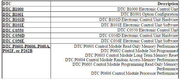
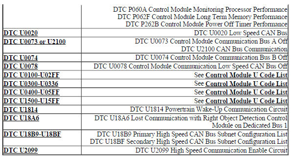
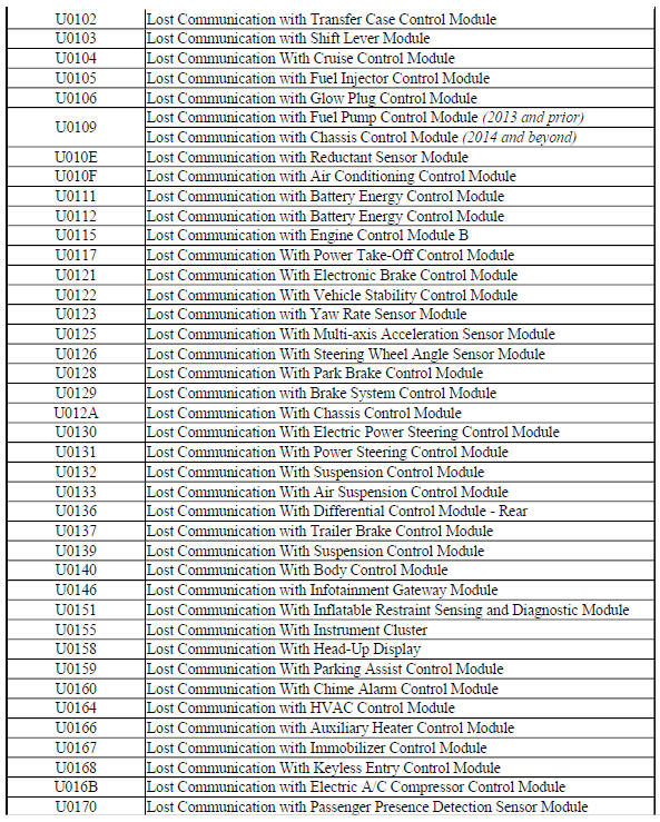
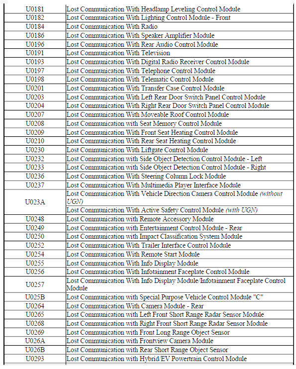
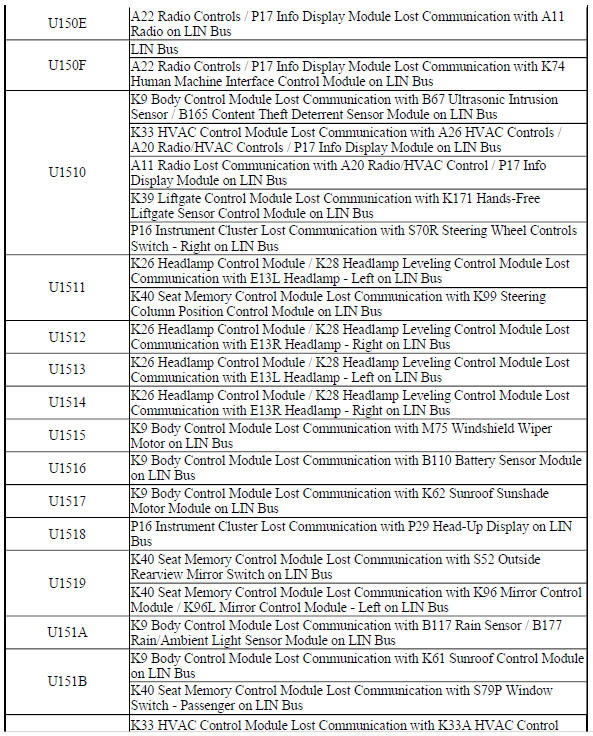
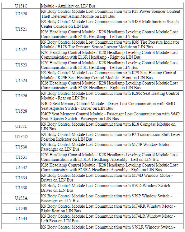
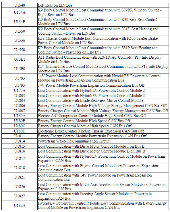
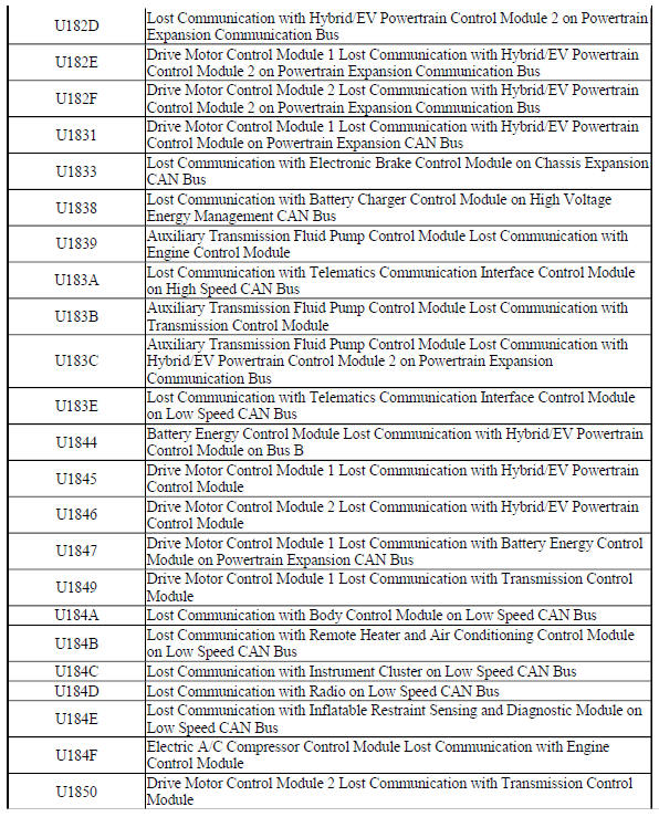
CONTROL MODULE U CODE LIST
This list includes all Data Communications related U-code DTCs in alphanumeric order with descriptors for all devices. Not all DTCs listed will be applicable to all vehicles.
For symptom byte information, refer to Symptom Byte List .
Control Module U Code List
.jpg)
.jpg)
.jpg)
.jpg)
DTC B1000: Electronic control unit
Diagnostic Instructions
- Perform the Diagnostic System Check - Vehicle prior to using this diagnostic procedure.
- Review Strategy Based Diagnosis for an overview of the diagnostic approach.
- Diagnostic Procedure Instructions provides an overview of each diagnostic category.
DTC Descriptor
DTC B1000
Electronic Control Unit
For symptom byte information, refer to Symptom Byte List .
Circuit/System Description
The internal fault detection is handled inside the device. The symptom byte information is for engineering reference only. No external circuit diagnosis is involved.
Conditions for Running the DTC
The device runs the program to detect an internal fault when power up is commanded. The only requirements are voltage and ground. This program runs even if the voltage is out of the valid operating range.
Conditions for Setting the DTC
The device has detected an internal malfunction.
Action Taken When the DTC Sets
The device refuses all additional inputs.
Conditions for Clearing the DTC
- A current DTC clears when the malfunction is no longer present.
- A history DTC clears when the device ignition cycle counter reaches the reset threshold of 50, without a repeat of the malfunction.
Diagnostic Aids
- This DTC may be stored as a history DTC without affecting the operation of the device.
- If stored only as a history DTC and not retrieved as a current DTC, do not replace the device.
- If this DTC is retrieved as both a current and history DTC, replace the device that set the DTC.
Reference Information
Schematic Reference
- Data Communication Schematics (Encore), Data Communication Schematics (Encore)
- Control Module References
Connector End View Reference
WIRING SYSTEMS AND POWER MANAGEMENT - COMPONENT CONNECTOR END VIEWS - INDEX - ENCORE WIRING SYSTEMS AND POWER MANAGEMENT - COMPONENT CONNECTOR END VIEWS - INDEX - Encore
Description and Operation
Data Link Communications Description and Operation
Electrical Information Reference
- Circuit Testing
- Connector Repairs
- Testing for Intermittent Conditions and Poor Connections
- Wiring Repairs
Scan Tool Reference
Control Module References for scan tool information
Circuit/System Verification
- Ignition ON.
- Verify DTC B1000 is not set.
If DTC B1000 is set
Replace the device that set the DTC.
If DTC B1000 is not set
- All OK
Repair Instructions
Perform the Diagnostic Repair Verification after completing the repair.
Control Module References for device replacement, programming and setup
DTC B1001: OPTION CONFIGURATION
Diagnostic Instructions
- Perform the Diagnostic System Check - Vehicle prior to using this diagnostic procedure.
- Review Strategy Based Diagnosis for an overview of the diagnostic approach.
- Diagnostic Procedure Instructions provides an overview of each diagnostic category.
DTC Descriptor
DTC B1001
Option Configuration
For symptom byte information, refer to Symptom Byte List .
Circuit/System Description
Some devices must be configured with serial numbers, vehicle options, or other information. If a device was not properly configured after installation that device may set DTC B1001. The symptom byte information is for engineering reference only. No external circuit diagnosis is involved.
Conditions for Running the DTC
Battery voltage is between 9-16 V and data link communications operate normally.
Conditions for Setting the DTC
The device is not configured properly.
Conditions for Clearing the DTC
- A current DTC clears when the malfunction is no longer present.
- A history DTC clears when the device ignition cycle counter reaches the reset threshold, without a repeat of the malfunction.
Reference Information
Schematic Reference
- Data Communication Schematics (Encore), Data Communication Schematics (Encore)
- Control Module References
Connector End View Reference
WIRING SYSTEMS AND POWER MANAGEMENT - COMPONENT CONNECTOR END VIEWS - INDEX - ENCORE WIRING SYSTEMS AND POWER MANAGEMENT - COMPONENT CONNECTOR END VIEWS - INDEX - Encore
Description and Operation
Data Link Communications Description and Operation
Electrical Information Reference
- Circuit Testing
- Connector Repairs
- Testing for Intermittent Conditions and Poor Connections
- Wiring Repairs
Scan Tool Reference
Control Module References for scan tool information
Circuit/System Verification
- Ignition ON.
- Verify DTC B1001 is not set.
If DTC B1001 is set
- Program the device that set the DTC.
- Verify the DTC does not set.
- If the DTC sets, replace the device that set the DTC.
- If the DTC does not set
- All OK.
If DTC B1001 is not set
- All OK
Repair Instructions
Perform the Diagnostic Repair Verification after completing the repair.
Control Module References for device replacement, programming and setup
DTC B101D: Electronic control unit hardware
Diagnostic Instructions
- Perform the Diagnostic System Check - Vehicle prior to using this diagnostic procedure.
- Review Strategy Based Diagnosis for an overview of the diagnostic approach.
- Diagnostic Procedure Instructions provides an overview of each diagnostic category.
DTC Descriptor
DTC B101D
Electronic Control Unit Hardware
For symptom byte information, refer to Symptom Byte List .
Circuit/System Description
The internal fault detection is handled inside the device. The symptom byte information is for engineering reference only. No external circuit diagnosis is involved.
Conditions for Running the DTC
- The device runs the program to detect an internal fault when power up is commanded. The only requirements are voltage and ground. This program runs even if the voltage is out of the valid operating range.
- The keyless entry control module will set this DTC with symptom byte 39 when the keyless entry control module antenna is activated.
Conditions for Setting the DTC
The device has detected an internal malfunction.
Action Taken When the DTC Sets
The device refuses all additional inputs
Conditions for Clearing the DTC
- A current DTC clears when the malfunction is no longer present.
- A history DTC clears when the device ignition cycle counter reaches the reset threshold of 50, without a repeat of the malfunction.
Diagnostic Aids
This DTC may be stored as a history DTC without affecting the operation of the device.
Do not replace a device based only on DTC B101D being set in history with the exception of the following devices:
- K36 Inflatable Restraint Sensing and Diagnostic Module (SDM)
- K85 Passenger Presence Detection Module
If DTC B101D is set as current, replace the appropriate device.
Reference Information
Schematic Reference
- Data Communication Schematics (Encore), Data Communication Schematics (Encore)
- Control Module References
Connector End View Reference
WIRING SYSTEMS AND POWER MANAGEMENT - COMPONENT CONNECTOR END VIEWS - INDEX - ENCORE WIRING SYSTEMS AND POWER MANAGEMENT - COMPONENT CONNECTOR END VIEWS - INDEX - Encore
Description and Operation
Data Link Communications Description and Operation
Electrical Information Reference
- Circuit Testing
- Connector Repairs
- Testing for Intermittent Conditions and Poor Connections
- Wiring Repairs
Scan Tool Reference
Control Module References for scan tool information
Circuit/System Verification
- Ignition ON.
- Verify DTC B101D is not set.
- If DTC B101D is set with symptom byte 43
- Program the device that set the DTC.
- Verify the DTC does not set.
- If the DTC sets, replace the device that set the DTC.
- If the DTC does not set
- All OK.
- If DTC B101D is set with any symptom byte, except symptom byte 43
Replace the device that set the DTC.
- If DTC B101D is not set
- All OK
Repair Instructions
Perform the Diagnostic Repair Verification after completing the repair.
Control Module References for device replacement, programming and setup
DTC B101E: Electronic control unit software
Diagnostic Instructions
- Perform the Diagnostic System Check - Vehicle prior to using this diagnostic procedure.
- Review Strategy Based Diagnosis for an overview of the diagnostic approach.
- Diagnostic Procedure Instructions provides an overview of each diagnostic category.
DTC Descriptor
DTC B101E
Electronic Control Unit Software
For symptom byte information, refer to Symptom Byte List .
Circuit/System Description
Some devices must be configured with specific software, serial numbers, vehicle options, or other information.
If a device was not properly configured after installation that module may set DTC B101E. The symptom byte information is for engineering reference only. No external circuit diagnosis is involved.
Conditions for Running the DTC
Battery voltage is between 9-16 V and data link communications operate normally.
Conditions for Setting the DTC
The device is not configured properly.
Conditions for Clearing the DTC
- A current DTC clears when the malfunction is no longer present.
- A history DTC clears when the device ignition cycle counter reaches the reset threshold, without a repeat of the malfunction.
Reference Information
Schematic Reference
- Data Communication Schematics (Encore), Data Communication Schematics (Encore)
- Control Module References
Connector End View Reference
WIRING SYSTEMS AND POWER MANAGEMENT - COMPONENT CONNECTOR END VIEWS - INDEX - ENCORE WIRING SYSTEMS AND POWER MANAGEMENT - COMPONENT CONNECTOR END VIEWS - INDEX - Encore
Description and Operation
Data Link Communications Description and Operation
Electrical Information Reference
- Circuit Testing
- Connector Repairs
- Testing for Intermittent Conditions and Poor Connections
- Wiring Repairs
Scan Tool Reference
Control Module References for scan tool information
Circuit/System Verification
- Ignition ON.
- Verify that DTC U0028 or U0029 is not set.
- If any of the DTCs are set
Refer to Diagnostic Trouble Code (DTC) List - Vehicle .
- If none of the DTCs are set
- Verify DTC B101E is not set.
- If DTC B101E is set
- Program the device that set the DTC.
- Verify the DTC does not set.
- If the DTC sets, replace the device that set the DTC.
- If the DTC does not set
- All OK.
- If DTC B101E is not set
- All OK
Repair Instructions
Perform the Diagnostic Repair Verification after completing the repair.
Control Module References for device replacement, programming and setup
DTC C0550: ELECTRONIC CONTROL UNIT
Diagnostic Instructions
- Perform the Diagnostic System Check - Vehicle prior to using this diagnostic procedure.
- Review Strategy Based Diagnosis for an overview of the diagnostic approach.
- Diagnostic Procedure Instructions provides an overview of each diagnostic category.
DTC Descriptor
DTC C0550
Electronic Control Unit
For symptom byte information, refer to Symptom Byte List .
Circuit/System Description
The internal fault detection is handled inside the device. The symptom byte information is for engineering reference only. No external circuit diagnosis is involved.
Conditions for Running the DTC
The device runs the program to detect an internal fault when power up is commanded. The only requirements are voltage and ground. This program runs even if the voltage is out of the valid operating range.
Conditions for Setting the DTC
The device has detected an internal malfunction
Action Taken When the DTC Sets
The device refuses all additional inputs.
Conditions for Clearing the DTC
- A current DTC clears when the malfunction is no longer present.
- A history DTC clears when the device ignition cycle counter reaches the reset threshold of 50, without a repeat of the malfunction.
Diagnostic Aids
- This DTC may be stored as a history DTC without affecting the operation of the device.
- If stored only as a history DTC and not retrieved as a current DTC, do not replace the device.
- If this DTC is retrieved as both a current and history DTC, replace the device that set the DTC.
Reference Information
Schematic Reference
- Data Communication Schematics (Encore), Data Communication Schematics (Encore)
- Control Module References
Connector End View Reference
WIRING SYSTEMS AND POWER MANAGEMENT - COMPONENT CONNECTOR END VIEWS - INDEX - ENCORE WIRING SYSTEMS AND POWER MANAGEMENT - COMPONENT CONNECTOR END VIEWS - INDEX - Encore
Description and Operation
Data Link Communications Description and Operation
Electrical Information Reference
- Circuit Testing
- Connector Repairs
- Testing for Intermittent Conditions and Poor Connections
- Wiring Repairs
Scan Tool Reference
Control Module References for scan tool information
Circuit/System Verification
- Ignition ON.
- Verify that DTC B1325, B1330, B1370, B1380, B1424, B1440, B1441, B1517, C0800, C0899, C12E1, P0560, or P0562 is not set.
- If any of the DTCs are set
Refer to Diagnostic Trouble Code (DTC) List - Vehicle to diagnose those DTC's first.
- If none of the DTCs are set
- Verify DTC C0550 is not set.
- If DTC C0550 is set symptom byte 39 or 43
- Program the device that set the DTC.
- Verify the DTC does not set.
- If the DTC sets, replace the device that set the DTC.
- If the DTC does not set
- All OK.
- If DTC C0550 is set with any symptom byte, except symptom byte 39 or 43
Replace the device that set the DTC.
- If DTC C0550 is not set
- All OK
Repair Instructions
Perform the Diagnostic Repair Verification after completing the repair.
Control Module References for device replacement, programming and setup
DTC C056D: Electronic control unit hardware
Diagnostic Instructions
- Perform the Diagnostic System Check - Vehicle prior to using this diagnostic procedure.
- Review Strategy Based Diagnosis for an overview of the diagnostic approach.
- Diagnostic Procedure Instructions provides an overview of each diagnostic category.
DTC Descriptor
DTC C056D
Electronic Control Unit Hardware
For symptom byte information, refer to Symptom Byte List .
Circuit/System Description
The internal fault detection is handled inside the device. The symptom byte information is for engineering reference only. No external circuit diagnosis is involved.
Conditions for Running the DTC
The device runs the program to detect an internal fault when power up is commanded. The only requirements are voltage and ground. This program runs even if the voltage is out of the valid operating range.
Conditions for Setting the DTC
The device has detected an internal malfunction.
Action Taken When the DTC Sets
The device refuses all additional inputs.
Conditions for Clearing the DTC
- A current DTC clears when the malfunction is no longer present.
- A history DTC clears when the device ignition cycle counter reaches the reset threshold of 50, without a repeat of the malfunction.
Diagnostic Aids
- This DTC may be stored as a history DTC without affecting the operation of the device.
- If stored only as a history DTC and not retrieved as a current DTC, do not replace the device.
- If this DTC is retrieved as both a current and history DTC, replace the device that set the DTC.
Reference Information
Schematic Reference
- Data Communication Schematics (Encore), Data Communication Schematics (Encore)
- Control Module References
Connector End View Reference
WIRING SYSTEMS AND POWER MANAGEMENT - COMPONENT CONNECTOR END VIEWS - INDEX - ENCORE WIRING SYSTEMS AND POWER MANAGEMENT - COMPONENT CONNECTOR END VIEWS - INDEX - Encore
Description and Operation
Data Link Communications Description and Operation
Electrical Information Reference
- Circuit Testing
- Connector Repairs
- Testing for Intermittent Conditions and Poor Connections
- Wiring Repairs
Scan Tool Reference
Control Module References for scan tool information
Circuit/System Verification
- Ignition ON.
- Verify DTC C056D is not set.
- If DTC C056D is set in a device that can be programmed
- Program the device that set the DTC.
- Verify the DTC does not set.
- If the DTC sets, replace the device that set the DTC.
- If the DTC does not set
- All OK.
If DTC C056D is set in a device that cannot be programmed
Replace the device that set the DTC.
- If DTC C056D is not set
- All OK
Repair Instructions
Perform the Diagnostic Repair Verification after completing the repair.
Control Module References for device replacement, programming and setup
DTC C056E: Electronic control unit software
Diagnostic Instructions
- Perform the Diagnostic System Check - Vehicle prior to using this diagnostic procedure.
- Review Strategy Based Diagnosis for an overview of the diagnostic approach.
- Diagnostic Procedure Instructions provides an overview of each diagnostic category
DTC Descriptor
DTC C056E
Electronic Control Unit Software
For symptom byte information, refer to Symptom Byte List .
Circuit/System Description
Some devices must be configured with specific software, serial numbers, vehicle options, or other information.
If a device was not properly configured after installation that module may set DTC C056E. The symptom byte information is for engineering reference only. No external circuit diagnosis is involved.
Conditions for Running the DTC
Battery voltage is between 9-16 V and data link communications operate normally.
Conditions for Setting the DTC
- A current DTC clears when the malfunction is no longer present.
- A history DTC clears when the device ignition cycle counter reaches the reset threshold, without a repeat of the malfunction.
Reference Information
Schematic Reference
Data Communication Schematics (Encore), Data Communication Schematics (Encore)
Connector End View Reference
WIRING SYSTEMS AND POWER MANAGEMENT - COMPONENT CONNECTOR END VIEWS - INDEX - ENCORE WIRING SYSTEMS AND POWER MANAGEMENT - COMPONENT CONNECTOR END VIEWS - INDEX - Encore
Description and Operation
Data Link Communications Description and Operation
Electrical Information Reference
- Circuit Testing
- Connector Repairs
- Testing for Intermittent Conditions and Poor Connections
- Wiring Repairs
Scan Tool References
Control Module References for scan tool information
Circuit/System Verification
- Ignition ON.
- Verify DTC C056E is not set.
- If DTC C056E is set
- Program the device that set the DTC.
- Verify the DTC does not set.
- If the DTC sets, replace the device that set the DTC.
- If the DTC does not set
- All OK.
- If DTC C056E is not set
- All OK
Repair Instructions
Perform the Diagnostic Repair Verification after completing the repair.
Control Module References for device replacement, programming and setup
DTC P0601-P0606, P060A, P062F, OR P262B: CONTROL MODULE READ ONLY MEMORY/PROCESSOR PERFORMANCE
Diagnostic Instructions
- Perform the Diagnostic System Check - Vehicle prior to using this diagnostic procedure.
- Review Strategy Based Diagnosis for an overview of the diagnostic approach.
- Diagnostic Procedure Instructions provides an overview of each diagnostic category.
DTC Descriptor
DTC P0601
Control Module Read Only Memory Performance
DTC P0602
Control Module Not Programmed
DTC P0603
Control Module Long Term Memory Reset
DTC P0604
Control Module Random Access Memory Performance
DTC P0605
Control Module Programming Read Only Memory Performance
DTC P0606
Control Module Processor Performance
DTC P060A
Control Module Monitoring Processor Performance
DTC P062F
Control Module Long Term Memory Performance
DTC P262B
Control Module Power Off Timer Performance
For symptom byte information, refer to Symptom Byte List .
Circuit/System Description
This diagnostic applies to internal microprocessor integrity conditions within the device. This diagnostic also addresses if the device is not programmed. The device monitors its ability to read and write to the memory. It also monitors a timing function. No external circuits are involved.
Conditions for Running the DTC
- The ignition is ON.
- The system voltage is greater than 9.5 V.
Conditions for Setting the DTC
The device detects an internal malfunction or incomplete programming.
Action Taken When the DTC Sets
DTCs P0601-P0606, P060A, P062F, and P262B are Type A DTCs.
Conditions for Clearing the DTC
DTCs P0601-P0606, P060A, P062F, and P262B are Type A DTCs.
Diagnostic Aids
If stored only as a history DTC and not retrieved as a current DTC, do not replace the device.
Reference Information
Schematic Reference
Data Communication Schematics (Encore), Data Communication Schematics (Encore)
Connector End View Reference
WIRING SYSTEMS AND POWER MANAGEMENT - COMPONENT CONNECTOR END VIEWS - INDEX - ENCORE WIRING SYSTEMS AND POWER MANAGEMENT - COMPONENT CONNECTOR END VIEWS - INDEX - Encore
Description and Operation
Data Link Communications Description and Operation
Electrical Information Reference
- Circuit Testing
- Connector Repairs
- Testing for Intermittent Conditions and Poor Connections
- Wiring Repairs
DTC Type Reference
Powertrain Diagnostic Trouble Code (DTC) Type Definitions (LUV) , Powertrain Diagnostic Trouble Code (DTC) Type Definitions (2H0)
Scan Tool References
Control Module References for scan tool information
Circuit/System Verification
- Ignition ON.
- Verify that DTC P0602 is not set.
- If DTC P0602 is set
- Program the device that set the DTC.
- Verify that the DTC does not set.
- If the DTC sets, replace the device that set the DTC.
- If the DTC does not set
- All OK.
- If DTC P0602 is not set
- Verify that DTC P0601, P0603, P0604, P0605, P0606, P060A, P062F, or P262B is not set.
- If any of the DTCs are set
Replace the device that set the DTC.
- If none of the DTCs are set
- All OK
Repair Instructions
Perform the Diagnostic Repair Verification after completing the repair.
Control Module References for device replacement, programming and setup
DTC U0020:Low speed can bus
Diagnostic Instructions
- Perform the Diagnostic System Check - Vehicle prior to using this diagnostic procedure.
- Review Strategy Based Diagnosis for an overview of the diagnostic approach.
- Diagnostic Procedure Instructions provides an overview of each diagnostic category.
DTC Descriptors
DTC U0020
Low Speed CAN Bus
For symptom byte information, refer to Symptom Byte List .
Circuit/System Description
Devices connected to the GMLAN serial data circuits monitor for serial data communications during normal vehicle operation. Operating information and commands are exchanged among the devices. The devices have programmed information about what messages are needed to be exchanged on the serial data circuits. The messages are also supervised and some periodic messages are used by the receiver device as an availability indication of the transmitter device.
Conditions for Running the DTCs
- Supply voltage to the devices is in the normal operating range.
- The vehicle power mode requires serial data communication to occur.
- The DTC U2100 does not have a current status.
Conditions for Setting the DTC
A supervised periodic message that includes the transmitter device availability has not been received
Action Taken When the DTCs Sets
The device uses a default value for the missing parameter.
Conditions for Clearing the DTC
- A current DTC clears when the malfunction is no longer present.
- A history DTC clears when the device ignition cycle counter reaches the reset threshold, without a repeat of the malfunction
Circuit/System Verification
Diagnosis of this DTC is accomplished via the symptom or an additional DTC. Refer to Scan Tool Does Not Communicate with Low Speed GMLAN Device, or Diagnostic Trouble Code (DTC) List - Vehicle .
DTC U0073 OR U2100: Can bus communication
Diagnostic Instructions
- Perform the Diagnostic System Check - Vehicle prior to using this diagnostic procedure.
- Review Strategy Based Diagnosis for an overview of the diagnostic approach.
- Diagnostic Procedure Instructions provides an overview of each diagnostic category.
DTC Descriptors
DTC U0073
Control Module Communication Bus A Off
DTC U2100
CAN Bus Communication
For symptom byte information, refer to Symptom Byte List .
Circuit/System Description
The serial data circuits are used to communicate information between the devices. The serial data circuits also connect directly to the data link connector (DLC).
Conditions for Running the DTCs
- Supply voltage to the devices is in the normal operating range.
- The vehicle power mode requires serial data communications.
Conditions for Setting the DTC
The device setting the DTC has attempted to establish communications on the serial data circuits more than 3 times in 5 s.
Action Taken When the DTCs Sets
- The device suspends all message transmission.
- The device uses default values for all parameters received on the serial data circuits.
- In the transmission control module, DTC U0073 will cause the transmission to go into default gears.
- In the engine control module and transmission control module, DTC U0073 will cause the malfunction indicator lamp (MIL) to illuminate.
- If equipped with eAssist, DTC U0073 in the hybrid powertrain control module is a type B DTC and will cause the malfunction indicator lamp to illuminate and result in the engine operating in conventional engine mode and will maintain 14 V module operation.
- The device inhibits the setting of all other communication DTCs.
Conditions for Clearing the DTC
- The engine control module or transmission control module turns OFF the MIL after 4 consecutive ignition cycles that the diagnostic runs and does not fail.
- If equipped with eAssist, the hybrid powertrain control module turns off the MIL after the diagnostic runs and does not fail during subsequent ignition cycles. Normal operation will resume 5 s after subsequent ignition cycle.
- A current DTC clears when the malfunction is no longer present.
- A history DTC clears when the device ignition cycle counter reaches the reset threshold of 50, without a repeat of the malfunction.
Circuit/System Verification
- Refer to Data Link References to determine which serial data communication system is used for a specific device.
- This DTC may not be retrieved with a current status. Diagnosis is
accomplished using the symptom.
Refer to Symptoms - Data Communications.
DTC U0074: Control module communication bus B OFF
Diagnostic Instructions
- Perform the Diagnostic System Check - Vehicle prior to using this diagnostic procedure.
- Review Strategy Based Diagnosis for an overview of the diagnostic approach.
- Diagnostic Procedure Instructions provides an overview of each diagnostic category.
DTC Descriptor
DTC U0074
Control Module Communication Bus B Off
For symptom byte information, refer to Symptom Byte List .
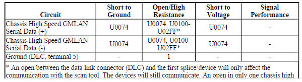
Diagnostic Fault Information
.jpg)
Circuit/System Description
The devices connected to the chassis high speed GMLAN serial data circuits monitor for serial data communications during normal vehicle operation. Operating information and commands are exchanged among the devices when the ignition switch is in any position other than OFF. The chassis high speed GMLAN serial data bus uses terminating resistors that are in parallel with the chassis high speed GMLAN (+) and (-) circuits.
Conditions for Running the DTC
The system voltage is between 9-16 V.
Conditions for Setting the DTC
A supervised periodic message that includes the transmitter device availability has not been received.
Action Taken When the DTC Sets
Specific subsystems will not function.
Conditions for Clearing the DTC
- A current DTC clears when the malfunction is no longer present.
- A history DTC clears when the device ignition cycle counter reaches the reset threshold of 50, without a repeat of the malfunction.
Diagnostic Aids
- Use the Data Link References to identify the chassis high speed GMLAN devices.
- Sometimes, while diagnosing a specific customer concern or after a repair, you may notice a history Ucode present. However, there is no associated "current" or "active" status. Loss-of-communication Ucodes such as these can set for a variety of reasons. Many times, they are transparent to the vehicle operator and technician, and/or have no associated symptoms. Eventually, they will erase themselves automatically after a number of fault-free ignition cycles. This condition would most likely be attributed to one of these scenarios:
- A device on the data communication circuit was disconnected while the communication circuit is awake.
- Power to one or more devices was interrupted during diagnosis.
- A low battery condition was present, so some devices stop communicating when battery voltage drops below a certain threshold.
- Battery power was restored to the vehicle and devices on the communication circuit did not all reinitialize at the same time.
- If a loss-of-communication U code appears in history for no apparent reason, it is most likely associated with one of the scenarios above. These are all temporary conditions and should never be interpreted as an intermittent fault, causing you to replace a part.
- Do not replace a device reporting a U code. The U code identifies which device needs to be diagnosed for a communication issue.
- Communication may be available between some devices and the scan tool with the chassis high speed GMLAN serial data system inoperative. This condition is due to those devices using multiple serial data communication systems.
- An open in the DLC ground circuit terminal 5 will allow the scan tool to operate but not communicate with the vehicle.
- Technicians may find various Local Area Network (LAN) communication Diagnostic Trouble Codes (DTC).
- Some devices may not have internal protection for specific voltage outputs and may open a battery positive voltage or ignition voltage source fuse. If a voltage input fuse is open and no short is found in that circuit, ensure that no device output voltage circuit is shorted to ground before replacing the device.
Reference Information
Schematic Reference
- Data Communication Schematics (Encore), Data Communication Schematics (Encore)
- Control Module References
Connector End View Reference
WIRING SYSTEMS AND POWER MANAGEMENT - COMPONENT CONNECTOR END VIEWS - INDEX - ENCORE WIRING SYSTEMS AND POWER MANAGEMENT - COMPONENT CONNECTOR END VIEWS - INDEX - Encore
Description and Operation
Data Link Communications Description and Operation
Electrical Information Reference
- Circuit Testing
- Connector Repairs
- Testing for Intermittent Conditions and Poor Connections
- Wiring Repairs
Scan Tool Reference
Control Module References for scan tool information
Circuit/System Verification
- Ignition ON.
- Verify two or more devices are not communicating on the chassis high
speed GMLAN serial data circuit.
Refer to Data Link References to determine how many devices should be communicating on the bus.
If only one device is not communicating
Refer to Circuit/System Testing - Testing the Device Circuits.
If two or more devices are not communicating
- Ignition OFF, all access doors closed, all vehicle systems OFF, and all keys at least 3 m (9.8 ft) away from vehicle. Disconnect the scan tool from the X84 Data Link Connector. The following tests will be done at the X84 Data Link Connector. It may take up to 2 minutes for all vehicle systems to power down.
- Test for less than 10 ohms between the ground circuit terminal 5 and ground.
- If 10 ohms or greater
- Ignition OFF.
- Test for less than 2 ohms in the ground circuit end to end.
- If 2 ohms or greater, repair the open/high resistance in the circuit.
- If less than 2 ohms, repair the open/high resistance in the ground connection.
If less than 10 ohms
- Ignition ON.
- Test for less than 4.5 V between the serial data circuits listed below and ground:
- Chassis high speed GMLAN serial data terminal 12
- Chassis high speed GMLAN serial data terminal 13
If 4.5 V or greater
Refer to Circuit/System Testing - Testing the Serial Data Circuits for a Short to Voltage.
If less than 4.5 V
- Ignition OFF, all access doors closed, all vehicle systems OFF, and all keys at least 3 m (9.8 ft) away from vehicle. It may take up to 2 minutes for all vehicle systems to power down.
- Test for greater than 100 ohms between the serial data circuits listed below and ground:
- Chassis high speed GMLAN serial data terminal 12
- Chassis high speed GMLAN serial data terminal 13
If 100 ohms or less
Refer to Circuit/System Testing - Testing the Serial Data Circuits for a Short to Ground.
If greater than 100 ohms
- Test for 50-70 ohms between the serial data circuit terminals 12 and 13:
If less than 35 ohms
Refer to Circuit/System Testing - Testing the Serial Data Circuits for a Short between the Circuits.
If between 35-50 ohms
There may be a third terminating resistor between the serial data circuits. This can happen if the incorrect device is installed. Some devices are available with and without the terminating resistors installed to reduce the need of terminating resistors in the wiring harness. Refer to Circuit/System Testing - Testing the Serial Data Circuits for a Short between the Circuits.
If greater than 70 ohms but less than infinite
Refer to Circuit/System Testing - Testing the Serial Data Circuits for an Open/High Resistance.
If infinite resistance
Repair the open/high resistance in the circuit between the X84 Data Link Connector and the first splice/device in the serial data circuit.
If between 50-70 ohms
- Refer to Circuit/System Testing - Testing the Device Circuits.
Circuit/System Testing
NOTE: Each device may need to be disconnected to isolate a circuit fault.
Use the schematic to identify the following:
- Chassis high speed GMLAN devices the vehicle is equipped with
- Chassis high speed GMLAN serial data circuit terminating resistors
- Device locations on the chassis high speed GMLAN serial data circuits
- Each device's ground, B+, ignition, and chassis high speed GMLAN serial data circuit terminals
Some devices with an internal terminating resistor have a loop in the harness that connects the internal terminating resistor to the serial data circuit. When wired this way, test these loop circuits for the appropriate failure mode short to voltage, short to ground, or open/high resistance prior to replacing the device for each of the following tests.
Testing the Serial Data Circuits for a Short to Voltage
- Ignition OFF, disconnect the harness connectors with the chassis high speed GMLAN serial data circuits at an easily accessible device, ignition ON.
- Test for greater than 4.5 V between each serial data circuit at the device connector that was just disconnected and ground.
If each serial data circuit is 4.5 V or less
- Ignition OFF.
- Test for less than 10 ohms between each of the device's ground circuit terminals and ground.
- If 10 ohms or greater, repair the open/high resistance in the circuit.
- If less than 10 ohms, replace the device that was disconnected.
If any serial data circuit is greater than 4.5 V
- Ignition OFF, disconnect the harness connectors with the chassis high speed GMLAN serial data circuits at another device, in the direction of the circuit shorted to voltage, ignition ON.
- Test for greater than 4.5 V between each serial data circuit at the device connector that was just disconnected and ground.
If each serial data circuit is 4.5 V or less
- Ignition OFF.
- Test for less than 10 ohms between each of the device's ground circuit terminals and ground.
- If 10 ohms or greater, repair the open/high resistance in the circuit.
- If less than 10 ohms, replace the device that was disconnected.
If any serial data circuit is greater than 4.5 V
- Repeat step 3 until one of the following conditions are isolated:
- A short to voltage on the serial data circuit between two devices or splice packs, if equipped.
- A short to voltage on the serial data circuit between a device and a terminating resistor.
Testing the Serial Data Circuits for a Short to Ground
- Ignition OFF, all access doors closed, all vehicle systems OFF, and all keys at least 3 m (9.8 ft) away from vehicle. It may take up to 2 minutes for all vehicle systems to power down.
- Disconnect the harness connectors with the chassis high speed GMLAN serial data circuits at an easily accessible device.
- Test for greater than 100 ohms between each serial data circuit at the device connector that was just disconnected and ground.
If each serial data circuit is 100 ohms or greater
Replace the device that was disconnected.
If any serial data circuit is less than 100 ohms
- Disconnect the harness connectors with the chassis high speed GMLAN serial data circuits at another device, in the direction of the circuit shorted to ground.
- Test for greater than 100 ohms between each serial data circuit at the device connector that was just disconnected and ground.
If both serial data circuits are 100 ohms or greater
Replace the device that was disconnected.
If any serial data circuit is less than 100 ohms
- Repeat step 4 until one of the following conditions are isolated:
- A short to ground on the serial data circuit between two devices or splice packs, if equipped.
- A short to ground on the serial data circuit between a device and a terminating resistor.
- A short to ground on the serial data circuit between the X84 Data Link Connector and the first device or splice pack.
Testing the Serial Data Circuits for a Short between the Circuits
- Ignition OFF, all access doors closed, all vehicle systems OFF, and all keys at least 3 m (9.8 ft) away from vehicle. It may take up to 2 minutes for all vehicle systems to power down.
- Disconnect the harness connectors with the chassis high speed GMLAN serial data circuits at an easily accessible device that is not communicating.
- Test for greater than 110 ohms between each pair of serial data circuits at the device connector that was just disconnected.
If each pair of serial data circuits is 110 ohms or greater
Replace the device that was disconnected.
If any pair of serial data circuits is less than 110 ohms
- Connect the harness connectors at the device that was disconnected.
- Disconnect the harness connectors with the chassis high speed GMLAN serial data circuits at another device, in the direction of the circuit shorted together.
- Test for greater than 110 ohms between each pair of serial data circuits at the device connector that was just disconnected.
- If each pair of serial data circuits is 110 ohms or greater
Replace the device that was disconnected.
- If any pair of serial data circuits is less than 110 ohms
- Repeat step 4 until one of the following conditions are isolated:
- Serial data circuits shorted together between two devices or splice packs, if equipped.
- Serial data circuits shorted together between a device and a terminating resistor.
- Serial data circuits shorted together between the X84 Data Link Connector and the first device or splice pack.
- A shorted terminating resistor.
Testing the Serial Data Circuits for an Open/High Resistance
- Ignition OFF, all access doors closed, all vehicle systems OFF, and all keys at least 3 m (9.8 ft) away from vehicle. It may take up to 2 minutes for all vehicle systems to power down.
- Disconnect the harness connectors with the chassis high speed GMLAN serial data circuits at an easily accessible device that is not communicating.
- Test for less than 130 ohms between each pair of serial data circuits at the device connector that was just disconnected.
If each pair of serial data circuits is 130 ohms or less
Replace the device that was disconnected.
If any pair of serial data circuits is greater than 130 ohms
- Connect the harness connectors at the device that was disconnected.
- Disconnect the harness connectors with the chassis high speed GMLAN serial data circuits at another device, in the direction of the circuit with the open/high resistance.
- Test for less than 130 ohms between each pair of serial data circuits at the device connector that was just disconnected.
If each pair of serial data circuits is 130 ohms or less
Replace the device that was disconnected.
If any pair of serial data circuits is greater than 130 ohms
- Repeat step 4 until one of the following conditions are isolated:
- An open/high resistance on the serial data circuit between two devices or splice packs, if equipped.
- An open/high resistance on the serial data circuit between a device and a terminating resistor.
- An open/high resistance terminating resistor.
Testing the Device Circuits
- Ignition OFF, all access doors closed, all vehicle systems OFF, and all keys at least 3 m (9.8 ft) away from vehicle. It may take up to 2 minutes for all vehicle systems to power down.
- Disconnect the harness connectors at an easily accessible device that is not communicating.
- Test for less than 10 ohms between each ground circuit terminal and ground.
If 10 ohms or greater
- Ignition OFF.
- Test for less than 2 ohms in the ground circuit end to end.
- If 2 ohms or greater, repair the open/high resistance in the circuit.
- If less than 2 ohms, repair the open/high resistance in the ground connection.
If less than 10 ohms
- If equipped, verify a test lamp illuminates between each B+ circuit terminal and ground.
- If the test lamp does not illuminate and the circuit fuse is good
- Ignition OFF.
- Test for less than 2 ohms in the B+ circuit end to end.
- If 2 ohms or greater, repair the open/high resistance in the circuit.
- If less than 2 ohms, verify the fuse is not open and there is voltage at the fuse.
If the test lamp does not illuminate and the circuit fuse is open
- Ignition OFF.
- Test for infinite resistance between the B+ circuit and ground.
If less than infinite resistance, repair the short to ground on the circuit.
If infinite resistance, replace the disconnected device.
If the test lamp illuminates
- Ignition ON.
- If equipped, verify a test lamp illuminates between each ignition circuit terminal, which has a fuse in the circuit, and ground.
If the test lamp does not illuminate and the circuit fuse is good
- Ignition OFF.
- Test for less than 2 ohms in the ignition circuit end to end.
- If 2 ohms or greater, repair the open/high resistance in the circuit.
- If less than 2 ohms, verify the fuse is OK and there is voltage at the fuse.
If the test lamp does not illuminate and the circuit fuse is open
- Ignition OFF.
- Test for infinite resistance between the ignition circuit and ground.
- If less than infinite resistance, repair the short to ground on the circuit.
- If infinite resistance, replace the disconnected device.
If the test lamp illuminates
- If equipped, verify a test lamp illuminates between each ignition circuit terminal, which is controlled by a control module, and ground.
If the test lamp does not illuminate
- Ignition OFF, disconnect the harness connectors at the control module that controls the ignition circuit.
- Test for infinite resistance between the ignition circuit and ground.
- If less than infinite resistance, repair the short to ground on the circuit.
- If infinite resistance
- Test for less than 2 ohms in the ignition circuit end to end.
- If 2 ohms or greater, repair the open/high resistance in the circuit.
- If less than 2 ohms, replace the control module that controls the ignition circuit.
If the test lamp illuminates
- Ignition OFF, all access doors closed, all vehicle systems OFF, and all keys at least 3 m (9.8 ft) away from vehicle. It may take up to 2 minutes for all vehicle systems to power down.
- Test for less than 130 ohms between each pair of chassis high speed GMLAN serial data circuits at the device connector that was just disconnected.
If any pair of serial data circuits is greater than 130 ohms
Repair the open/high resistance in the serial data circuits between the disconnected device and the circuit splice in the serial data circuits.
- If each pair of serial data circuits is 130 ohms or less
- Replace the device that was disconnected.
Repair Instructions
Perform the Diagnostic Repair Verification after completing the repair.
- GMLAN and Media Oriented Systems Transport (MOST) Wiring Repairs
- Control Module References for device replacement, programming and setup
DTC U0078: Control module communication low speed can bus off
Diagnostic Instructions
- Perform the Diagnostic System Check - Vehicle prior to using this diagnostic procedure.
- Review Strategy Based Diagnosis for an overview of the diagnostic approach.
- Diagnostic Procedure Instructions provides an overview of each diagnostic category.
DTC Descriptor
DTC U0078
Control Module Communication Low Speed CAN Bus Off
For symptom byte information, refer to Symptom Byte List .
Circuit/System Description
The low speed GMLAN serial data bus is used to communicate information between the devices. The serial data is transmitted over a single wire to the appropriate devices. The low speed GMLAN serial data circuits also connect directly to the data link connector (DLC).
Conditions for Running the DTC
- Supply voltage to the devices are in the normal operating range.
- The vehicle power mode requires serial data communications.
Conditions for Setting the DTC
The device setting the DTC has attempted to establish communications on the serial data circuits more than 3 times in 5 s.
Action Taken When the DTC Sets
- The device suspends all message transmission.
- The device uses default values for all parameters received on the serial data circuits.
- The device inhibits the setting of all other communication DTCs.
Conditions for Clearing the DTC
- A current DTC clears when the malfunction is no longer present.
- A history DTC clears when the device ignition cycle counter reaches the reset threshold of 50, without a repeat of the malfunction.
Circuit/System Verification
- Ignition ON.
- Verify DTC U0078 is not set.
- If DTC U0078 is set
Refer to Scan Tool Does Not Communicate with Low Speed GMLAN Device.
- If DTC U0078 is not set
- All OK
DTC U0100-U02FF: See control module u code list
Diagnostic Instructions
- Perform the Diagnostic System Check - Vehicle prior to using this diagnostic procedure.
- Review Strategy Based Diagnosis for an overview of the diagnostic approach.
- Diagnostic Procedure Instructions provides an overview of each diagnostic category.
DTC Descriptor
For device DTC descriptors, refer to Control Module U Code List.
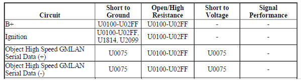
Diagnostic Fault Information
.jpg)
Circuit/System Description
The serial data circuit is the means by which the devices in the vehicle communicate with each other. Once the scan tool is connected to the serial data circuit through the Data Link Connector (DLC), the scan tool can be used to monitor each device for diagnostic purposes and to check for Diagnostic Trouble Codes (DTC). When the ignition switch is in RUN, each device communicating on the serial data circuit sends a state of health message to ensure that the device is operating properly. When a device stops communicating on the serial data circuit, for example if the device loses power or ground, the state of health message it normally sends on the serial data circuit disappears. Other devices on the serial data circuit, which expect to receive that state of health message, detect its absence; those devices in turn set a DTC associated with the loss of state of health of the non-communicating device. The DTC is unique to the device which is not communicating and one or more devices may set the same exact code. A loss of serial data communications DTC does not represent a failure of the devices that contain the stored code.
Conditions for Running the DTC
The system voltage is between 9-16 V.
Conditions for Setting the DTC
A supervised periodic message that includes the transmitter device availability has not been received.
Action Taken When the DTC Sets
- Specific subsystems will not function.
- DTC U0100 in the Transmission Control Module will cause the transmission to go into default gears.
- Both DTC U0100 in the Transmission Control Module and DTC U0101 in the Engine Control Module will cause the malfunction indicator lamp (MIL) to illuminate.
Conditions for Clearing the DTC
- The Engine Control Module or Transmission Control Module turns OFF the MIL after 4 consecutive ignition cycles that the diagnostic runs and does not fail.
- A current DTC clears when the malfunction is no longer present.
- A history DTC clears when the device ignition cycle counter reaches the reset threshold of 50, without a repeat of the malfunction.
Diagnostic Aids
Sometimes, while diagnosing a specific customer concern or after a repair, you may notice a history U code present. However, there is no associated "current" or "active" status. Loss of communication U codes such as these can set for a variety of reasons. Many times, they are transparent to the vehicle operator and technician, and/or have no associated symptoms. Eventually, they will erase themselves automatically after a number of fault-free ignition cycles. This condition would most likely be attributed to one of these scenarios:
- A device on the data communication circuit was disconnected while the communication circuit is awake.
- Power to one or more devices was interrupted during diagnosis.
- A low battery condition was present, so some devices stop communicating when battery voltage drops below a certain threshold.
- Battery power was restored to the vehicle and devices on the communication circuit did not all reinitialize at the same time.
- If a loss of communication U code appears in history for no apparent reason, it is most likely associated with one of the scenarios above. These are all temporary conditions and should never be interpreted as an intermittent fault, causing you to replace a part.
- A device may have a U code stored in history that does not require any repairs. Issues with late or corrupted messages between devices can be temporary with no apparent symptom or complaint; this does not mean the device is faulty. Do not replace a device based only on a history U code.
- Do not replace a device reporting a U code. The U code identifies which device needs to be diagnosed for a communication issue.
- Communication may be available between some devices and the scan tool with either the low or high speed GMLAN serial data system inoperative. This condition is due to those devices using multiple serial data communication systems.
- Use Data Link References to determine what serial data communications the device uses.
- Some devices may not have internal protection for specific control circuits and may open a B+ or ignition fuse. If a fuse is open and the B+ or ignition circuit is not shorted to ground, ensure none of the control circuits are shorted to ground before replacing the device.
- Some intermittent communication concerns may be caused by fretting corrosion on the serial data circuit terminals. Inspect all connectors at the device that set the communication DTC, the device that the communication DTC was set against, and any inline harness connectors between the two devices. Do not replace a device based only on fretting corrosion. Refer to bulletin 09-06-03-004 for assistance with the diagnosis and repair of this condition, if applicable.
- This diagnostic can be used for any device that is not communicating, regardless of the type of serial data circuit it is connected to, providing the vehicle is equipped with the device.
Reference Information
Schematic Reference
- Data Communication Schematics (Encore), Data Communication Schematics (Encore)
- Control Module References
Connector End View Reference
WIRING SYSTEMS AND POWER MANAGEMENT - COMPONENT CONNECTOR END VIEWS - INDEX - ENCORE WIRING SYSTEMS AND POWER MANAGEMENT - COMPONENT CONNECTOR END VIEWS - INDEX - Encore
Description and Operation
Data Link Communications Description and Operation
Electrical Information Reference
- Circuit Testing
- Connector Repairs
- Testing for Intermittent Conditions and Poor Connections
- Wiring Repairs
Scan Tool Reference
Control Module References for scan tool information
Circuit/System Verification
- Determine the device that is not communicating. Refer to Control Module U Code List.
- Verify that DTC U0073, U2100, U0074, U0078, U1814, U2099, B1325, B1330, B1370, B1380, B1424, B1440, B1441, B1517, C0800, C0899, C12E1, P0560, or P0562 is not set.
If any of the DTCs are set
Refer to Diagnostic Trouble Code (DTC) List - Vehicle .
If none of the DTCs are set
- Verify that DTC U0125 and DTC U0126 are not set together.
If both of the DTCs are set together
Refer to Scan Tool Does Not Communicate with Chassis High Speed GMLAN Device.
If both of the DTCs are not set together
- Refer to Circuit/System Testing.
Circuit/System Testing
NOTE: Use the schematics and connector end views to identify the device's ground, B+, ignition, accessory wakeup serial data, serial data communication enable, and serial data circuit terminals.
- Ignition OFF, all access doors closed, all vehicle systems OFF, and all keys at least 3 m (9.8 ft) away from vehicle. It may take up to 2 min for all vehicle systems to power down. Disconnect all the harness connectors at the device that is not communicating.
- Test for less than 10 ohms between each ground circuit terminal and ground.
If 10 ohms or greater
- Ignition OFF.
- Test for less than 2 ohms in the ground circuit end to end.
- If 2 ohms or greater, repair the open/high resistance in the circuit.
- If less than 2 ohms, repair the open/high resistance in the ground connection.
If less than 10 ohms
- Ignition ON.
- If equipped, verify a test lamp illuminates between each B+ circuit terminal and ground.
If the test lamp does not illuminate and the circuit fuse is good
- Ignition OFF.
- Test for less than 2 ohms in the B+ circuit end to end.
- If 2 ohms or greater, repair the open/high resistance in the circuit.
- If less than 2 ohms, verify the fuse is not open and there is voltage at the fuse
If the test lamp does not illuminate and the circuit fuse is open
- Ignition OFF.
- Test for infinite resistance between the B+ circuit and ground.
- If less than infinite resistance, repair the short to ground on the circuit.
- If infinite resistance, replace the disconnected device.
If the test lamp does not illuminate and the circuit fuse is open
- If equipped, verify a test lamp illuminates between each ignition circuit terminal and ground.
If the test lamp does not illuminate and the circuit fuse is good
- Ignition OFF.
- Test for less than 2 ohms in the ignition circuit end to end.
- If 2 ohms or greater, repair the open/high resistance in the circuit.
- If less than 2 ohms, verify the fuse is OK and there is voltage at the fuse.
If the test lamp does not illuminate and the circuit fuse is open
- Ignition OFF.
- Test for infinite resistance between the ignition circuit and ground.
- If less than infinite resistance, repair the short to ground on the circuit.
- If infinite resistance, replace the disconnected device.
If the test lamp illuminates
- If equipped, verify a test lamp illuminates between each ignition circuit terminal, which is controlled by a control module, and ground.
If the test lamp does not illuminate
- Ignition OFF, disconnect the harness connectors at the control module that controls the ignition circuit.
- Test for infinite resistance between the ignition circuit and ground.
- If less than infinite resistance, repair the short to ground on the circuit.
- If infinite resistance
- Test for less than 2 ohms in the ignition circuit end to end.
- If 2 ohms or greater, repair the open/high resistance in the circuit.
- If less than 2 ohms, replace the control module that controls the ignition circuit.
If the test lamp illuminates
- Test for less than 4.5 V between each GMLAN serial data circuit terminal and ground.
- If 4.5 V or greater between a low speed GMLAN serial data circuit and ground
Refer to Scan Tool Does Not Communicate with Low Speed GMLAN Device to test for a short to voltage.
- If 4.5 V or greater between a high speed GMLAN serial data circuit and ground
Refer to Scan Tool Does Not Communicate with High Speed GMLAN Device to test for a short to voltage.
- If less than 4.5 V
- Ignition OFF, all access doors closed, all vehicle systems OFF, and all keys at least 3 m (9.8 ft) away from vehicle. It may take up to 2 min for all vehicle systems to power down.
- Test for greater than 100 ohms between each GMLAN serial data circuit terminal and ground.
- If 100 ohms or less between a low speed GMLAN serial data circuit and ground
Refer to Scan Tool Does Not Communicate with Low Speed GMLAN Device to test for a short to ground.
- If 100 ohms or less between a high speed GMLAN serial data circuit and ground
Refer to Scan Tool Does Not Communicate with High Speed GMLAN Device to test for a short to ground.
If greater than 100 ohms
- Test for less than 2 ohms in each of the GMLAN serial data circuits end to end between the device harness connector and the X84 Data Link Connector terminals listed below
- Low speed GMLAN serial data circuit terminal 1
- High speed GMLAN serial data circuit terminal 6 or 14
- Mid speed GMLAN serial data circuit terminal 3 or 11
- Chassis high speed GMLAN serial data circuit terminal 12 or 13
- Object high speed GMLAN serial data circuit terminal 3 or 11
If 2 ohms or greater
Repair the open/high resistance in the serial data circuit between the non communicating device and the device setting the DTC or a serial data splice pack.
If less than 2 ohms
NOTE: The following test step is only applicable to a high speed GMLAN device with 2 pairs of serial data circuits or a high speed GMLAN device with an internal terminating resistor.
- Test for 110-130 ohms between each pair of high speed GMLAN serial data circuits.
If less than 110 ohms
Refer to Scan Tool Does Not Communicate with High Speed GMLAN Device to test for a short to ground or a short between the serial data circuits.
If greater than 130 ohms
Refer to Scan Tool Does Not Communicate with High Speed GMLAN Device to test for an open/high resistance in the serial data circuit.
If between 110-130 ohms
- Replace the device that is not communicating.
Repair Instructions
Perform the Diagnostic Repair Verification after completing the repair.
- GMLAN and Media Oriented Systems Transport (MOST) Wiring Repairs
- Control Module References for device replacement, programming and setup
DTC U0300-U0336: See control module u code list
Diagnostic Instructions
- Perform the Diagnostic System Check - Vehicle prior to using this diagnostic procedure.
- Review Strategy Based Diagnosis for an overview of the diagnostic approach.
- Diagnostic Procedure Instructions provides an overview of each diagnostic category.
DTC Descriptor
Refer to Control Module U Code List.
Circuit/System Description
Some devices must be configured with specific software, serial numbers, vehicle options, or other information.
If a device was not properly configured after installation that device may set the appropriate communication DTCs. No external circuit diagnosis is involved.
Conditions for Running the DTC
Battery voltage is between 9-16 V and data link communications operate normally.
Conditions for Setting the DTC
The device is not configured properly.
Conditions for Clearing the DTC
- A current DTC clears when the malfunction is no longer present.
- A history DTC clears when the device ignition cycle counter reaches the reset threshold, without a repeat of the malfunction.
Reference Information
Schematic Reference
- Data Communication Schematics (Encore), Data Communication Schematics (Encore)
- Control Module References
Connector End View Reference
WIRING SYSTEMS AND POWER MANAGEMENT - COMPONENT CONNECTOR END VIEWS - INDEX - ENCORE WIRING SYSTEMS AND POWER MANAGEMENT - COMPONENT CONNECTOR END VIEWS - INDEX - Encore
Description and Operation
Data Link Communications Description and Operation
Electrical Information Reference
- Circuit Testing
- Connector Repairs
- Testing for Intermittent Conditions and Poor Connections
- Wiring Repairs
Scan Tool Reference
Control Module References for scan tool information
Circuit/System Verification
- Ignition ON.
- Verify DTC U0300-U0336 is not set.
If DTC U0300-U0336 is set
- Program the device specified by the DTC descriptor.
- Verify the DTC does not set.
- If the DTC sets, replace the device specified by the DTC descriptor.
- If the DTC does not set
- All OK.
- If DTC U0300-U0336 is not set
- All OK
Repair Instructions
Perform the Diagnostic Repair Verification after completing the repair.
Control Module References for device replacement, programming and setup
DTC U0400-U05FF: See control module U code list
Diagnostic Instructions
- Perform the Diagnostic System Check - Vehicle prior to using this diagnostic procedure.
- Review Strategy Based Diagnosis for an overview of the diagnostic approach.
- Diagnostic Procedure Instructions provides an overview of each diagnostic category.
DTC Descriptor
Refer to Control Module U Code List.
Circuit/System Description
Some devices are constantly receiving information from other devices through serial data communication network. The invalid data code will be set when a receiving device detects a discrepancy in information it receives from another device causing its integrity to be questioned. The symptom byte listed in the DTC Descriptor is for engineering reference only. No external circuit diagnosis is involved.
Conditions for Running the DTC
Battery voltage is between 9-16 V and data link communications operate normally.
Conditions for Setting the DTC
The device is not configured properly.
Conditions for Clearing the DTC
- A current DTC clears when the malfunction is no longer present.
- A history DTC clears when the device ignition cycle counter reaches the reset threshold, without a repeat of the malfunction.
Reference Information
Schematic Reference
- Data Communication Schematics (Encore), Data Communication Schematics (Encore)
- Control Module References
Connector End View Reference
WIRING SYSTEMS AND POWER MANAGEMENT - COMPONENT CONNECTOR END VIEWS - INDEX - ENCORE WIRING SYSTEMS AND POWER MANAGEMENT - COMPONENT CONNECTOR END VIEWS - INDEX - Encore
Description and Operation
Data Link Communications Description and Operation
Electrical Information Reference
- Circuit Testing
- Connector Repairs
- Testing for Intermittent Conditions and Poor Connections
- Wiring Repairs
Scan Tool Reference
Control Module References for scan tool information
Circuit/System Verification
- Engine running for 10 s.
- Ignition ON, engine OFF, verify DTC U0400-U05FF is not set.
If DTC U0400-U05FF is set along with other DTCs set
Diagnose all other DTCs first. Refer to Diagnostic Trouble Code (DTC) List - Vehicle .
If DTC U0400-U05FF is set without other DTCs set
- Program the device specified by the DTC descriptor.
- Verify the DTC does not set.
- If the DTC sets, replace the appropriate device.
- If the DTC does not set
- All OK.
Repair Instructions
Perform the Diagnostic Repair Verification after completing the repair.
Control Module References for device replacement, programming and setup
DTC U1500-U15FF: SEE CONTROL MODULE U CODE LIST
Diagnostic Instructions
- Perform the Diagnostic System Check - Vehicle prior to using this diagnostic procedure.
- Review Strategy Based Diagnosis for an overview of the diagnostic approach.
- Diagnostic Procedure Instructions provides an overview of each diagnostic category.
DTC Descriptor
For device DTC descriptors, refer to Control Module U Code List.
Diagnostic Fault Information
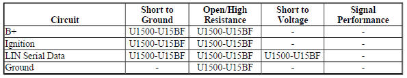
Circuit/System Description
The serial data is transmitted over a Local Interconnect Network (LIN) single wire network circuit bus between a master control module and other LIN devices within a particular subsystem. If serial data communication is lost between any of the LIN devices on the LIN bus network, a no communication code against the noncommunicating LIN device will be set. A master control module is the one that reports the non communication code.
Conditions for Running the DTC
The system voltage is between 9-16 V.
Conditions for Setting the DTC
A supervised periodic message that includes the transmitter device availability has not been received.
Action Taken When the DTC Sets
Specific subsystems will not function.
Conditions for Clearing the DTC
- A current DTC clears when the malfunction is no longer present.
- A history DTC clears when the device ignition cycle counter reaches the reset threshold of 50, without a repeat of the malfunction.
Diagnostic Aids
Sometimes, while diagnosing a specific customer concern or after a repair, you may notice a history U code present. However, there is no associated "current" or "active" status. Loss of communication U codes such as these can set for a variety of reasons. Many times, they are transparent to the vehicle operator and technician, and/or have no associated symptoms. Eventually, they will erase themselves automatically after a number of fault-free ignition cycles. This condition would most likely be attributed to one of these scenarios:
- A device on the data communication circuit was disconnected while the communication circuit is awake.
- Power to one or more devices was interrupted during diagnosis.
- A low battery condition was present, so some devices stop communicating when battery voltage drops below a certain threshold.
- Battery power was restored to the vehicle and devices on the communication circuit did not all reinitialize at the same time.
- If a loss of communication U code appears in history for no apparent reason, it is most likely associated with one of the scenarios above. These are all temporary conditions and should never be interpreted as an intermittent fault, causing you to replace a part.
- A device may have a U code stored in history that does not require any repairs. Issues with late or corrupted messages between devices can be temporary with no apparent symptom or complaint; this does not mean the device is faulty. Do not replace a device based only on a history U code.
- Do not replace a device reporting a U code. The U code identifies which device needs to be diagnosed for a communication issue.
- Communication will be available between the master control module and the scan tool if there is a loss of communications with any of the other LIN devices on the LIN bus network.
- Some devices may not have internal protection for specific control circuits and may open a B+ or ignition fuse. If a fuse is open and the B+ or ignition circuit is not shorted to ground, ensure none of the control circuits are shorted to ground before replacing the device.
- Some intermittent communication concerns may be caused by fretting corrosion on the serial data circuit terminals. Inspect all connectors at the device that set the communication DTC, the device that the communication DTC was set against, and any inline harness connectors between the two devices. Do not replace a device based only on fretting corrosion. Refer to bulletin 09-06-03-004 for assistance with the diagnosis and repair of this condition, if applicable.
- An open in the LIN bus serial data circuit between the splice pack and a LIN device will only affect that specific LIN device. This type of failure will set a loss of communication DTC for each LIN device affected and the other LIN devices will still communicate.
Reference Information
Schematic Reference
- Data Communication Schematics (Encore), Data Communication Schematics (Encore)
- Control Module References
Connector End View Reference
WIRING SYSTEMS AND POWER MANAGEMENT - COMPONENT CONNECTOR END VIEWS - INDEX - ENCORE WIRING SYSTEMS AND POWER MANAGEMENT - COMPONENT CONNECTOR END VIEWS - INDEX - Encore
Description and Operation
Data Link Communications Description and Operation
Electrical Information Reference
- Circuit Testing
- Connector Repairs
- Testing for Intermittent Conditions and Poor Connections
- Wiring Repairs
Scan Tool Reference
Control Module References for scan tool information
Circuit/System Verification
- Determine the LIN device that is not communicating. Refer to Control Module U Code List.
- Verify that DTC B1325, B1330, B1370, B1380, B1424, B1440, B1441, B1517, C0800, C0899, C12E1, P0560, or P0562 is not set.
If any of the DTCs are set
Refer to Diagnostic Trouble Code (DTC) List - Vehicle .
If none of the DTCs are set
- Verify that DTC U0100-U02FF is not set.
If any of the DTCs are set
Refer to DTC U0100-U02FF.
If none of the DTCs are set
- Refer to Circuit/System Testing.
Circuit/System Testing
NOTE:
- For some vehicles, both headlamps may be connected to the same LIN circuit through a splice. Or both LIN circuits to the headlamps may be internally connected at the connector of the K26 Headlamp Control Module or K28 Headlamp Leveling Control Module. A short in one headlamp or its LIN circuit may cause no communication to both headlamps. Ensure to diagnose both LIN circuits and headlamps prior to replacing a headlamp.
- Use the schematic to identify the following:
- The master control module and the LIN devices on the same LIN serial data circuit
- The master control module's LIN serial data circuit terminal and the LIN device's B+, ignition, ground, and LIN serial data circuit terminals
- Ignition OFF, all access doors closed, all vehicle systems OFF, and all keys at least 3 m (9.8 ft) away from vehicle. Disconnect the harness connector at a LIN device that is not communicating. It may take up to 2 min for all vehicle systems to power down.
- Test for less than 10 ohms between each ground circuit terminal and ground.
If 10 ohms or greater
- Ignition OFF.
- Test for less than 2 ohms in the ground circuit end to end.
- If 2 ohms or greater, repair the open/high resistance in the circuit.
- If less than 2 ohms, repair the open/high resistance in the ground connection.
If less than 10 ohms
- Ignition ON.
- Verify a test lamp illuminates between each B+ circuit terminal and ground, if equipped.
If the test lamp does not illuminate and the circuit fuse is good
- Ignition OFF.
- Test for less than 2 ohms in the B+ circuit end to end.
- If 2 ohms or greater, repair the open/high resistance in the circuit.
- If less than 2 ohms, verify the fuse is not open and there is voltage at the fuse
If the test lamp does not illuminate and the circuit fuse is open
- Ignition OFF.
- Test for infinite resistance between the B+ circuit and ground.
- If less than infinite resistance, repair the short to ground on the circuit.
- If infinite resistance, replace the disconnected LIN device.
If the test lamp illuminates
- Ignition ON.
- Verify a test lamp illuminates between each ignition circuit terminal and ground, if equipped.
If the test lamp does not illuminate and the circuit fuse is good
- Ignition OFF.
- Test for less than 2 ohms in the ignition circuit end to end.
- If 2 ohms or greater, repair the open/high resistance in the circuit.
- If less than 2 ohms, verify the fuse is OK and there is voltage at the fuse.
If the test lamp does not illuminate and the circuit fuse is open
- Ignition OFF.
- Test for infinite resistance between the ignition circuit and ground.
- If less than infinite resistance, repair the short to ground on the circuit.
- If infinite resistance, replace the disconnected LIN device.
If the test lamp illuminates
- Ignition ON.
- Verify a test lamp illuminates between each ignition circuit terminal, which is controlled by a control module, and ground, if equipped.
If the test lamp does not illuminate
- Ignition OFF, disconnect the harness connectors at the control module that controls the ignition circuit.
- Test for infinite resistance between the ignition circuit and ground.
- If less than infinite resistance, repair the short to ground on the circuit.
- If infinite resistance
- Test for less than 2 ohms in the ignition circuit end to end.
- If 2 ohms or greater, repair the open/high resistance in the circuit.
- If less than 2 ohms, replace the control module that controls the ignition circuit
- If the test lamp illuminates
- Ignition ON.
NOTE: For accurate voltage reading, disconnect the battery charger prior to performing the following test step.
- Test for 2-13 V between the LIN serial data circuit terminal and ground.
If less than 2 V
- Ignition OFF, disconnect the harness connector at the control module setting the DTC and all LIN devices that share the same LIN serial data circuit.
- Test for infinite resistance between the serial data circuit and ground.
- If less than infinite resistance, repair the short to ground on the circuit.
- If infinite resistance
- Test for less than 2 ohms in the serial data circuit end to end.
- If 2 ohms or greater, repair the open/high resistance in the circuit.
- If less than 2 ohms
- Reconnect the control module that set the DTC, ignition ON.
- Test for 2-13 V between the LIN serial data circuit terminal and ground.
- If less than 2 V, replace the control module setting the DTC.
- If greater than 2 V, replace the LIN device that causes a current DTC to set when connected
If greater than 13 V
- Ignition OFF, disconnect the harness connector at the control module setting the DTC and all LIN devices that share the same LIN serial data circuit.
- Ignition ON.
- Test for less than 1 V between the serial data circuit and ground.
- If 1 V or greater, repair the short to voltage on the circuit.
- If less than 1 V
- Ignition OFF, reconnect the control module that set the DTC, ignition ON.
- Test for 2-13 V between the LIN serial data circuit terminal and ground.
- If greater than 13 V, replace the control module setting the DTC.
- If less than 13 V, replace the LIN device that causes a current DTC to set when connected.
If between 2-13 V
- Replace the disconnected LIN device.
Repair Instructions
Perform the Diagnostic Repair Verification after completing the repair.
- GMLAN and Media Oriented Systems Transport (MOST) Wiring Repairs
- Control Module References for device replacement, programming and setup
DTC U1814: Powertrain wake-up communication circuit
Diagnostic Instructions
- Perform the Diagnostic System Check - Vehicle prior to using this diagnostic procedure.
- Review Strategy Based Diagnosis for an overview of the diagnostic approach.
- Diagnostic Procedure Instructions provides an overview of each diagnostic category
DTC Descriptor
DTC U1814
Powertrain Wake-Up Communication Circuit
For symptom byte information, refer to Symptom Byte List .
Diagnostic Fault Information
.jpg)
Circuit/System Description
The body control module (BCM) activates the ignition circuit, when the ignition key is in ACC, ON or START.
The ignition circuit wakes up the devices for serial data bus communication.
Conditions for Running the DTC
- The system voltage is between 9-16 V.
- The vehicle power mode master requires serial data communication to occur.
Conditions for Setting the DTC
The BCM senses a short to ground on the ignition circuit.
Action Taken When the DTC Sets
- The output command is turned off while the malfunction is present.
- The devices use a default value for the missing parameters until the next ignition cycle.
- The device(s) is never signaled. Therefore, the specific subsystem(s) will not function.
- The vehicle will not start while the circuit is shorted to ground.
Conditions for Clearing the DTC
A current DTC clears when the malfunction is no longer present.
A history DTC clears when the device ignition cycle counter reaches the reset threshold of 50, without a repeat of the malfunction.
Reference Information
Schematic Reference
- Data Communication Schematics (Encore), Data Communication Schematics (Encore)
- Control Module References
Connector End View Reference
WIRING SYSTEMS AND POWER MANAGEMENT - COMPONENT CONNECTOR END VIEWS - INDEX - ENCORE WIRING SYSTEMS AND POWER MANAGEMENT - COMPONENT CONNECTOR END VIEWS - INDEX - Encore
Description and Operation
Data Link Communications Description and Operation
Electrical Information Reference
- Circuit Testing
- Connector Repairs
- Testing for Intermittent Conditions and Poor Connections
- Wiring Repairs
Scan Tool Reference
Control Module References for scan tool information
Circuit/System Testing
NOTE: Use the schematic to determine which devices are on the K9 Body Control Module's ignition circuit terminal 22 X4. Use the connector end view to identify the ignition circuit terminal for each of those devices.
- Ignition OFF, disconnect the harness connectors at an easily accessible device that shares the K9 Body Control Module's ignition circuit terminal 22 X4. Ignition ON.
- Verify that the DTC U1814 remains current.
If the DTC becomes history
Replace the device that was just disconnected.
If the DTC remains current
- With the prior devices disconnected, repeat steps 1 and 2 for each device on the ignition circuit except the K9 Body Control Module.
- Ignition OFF, disconnect the X4 harness connector at the K9 Body Control Module.
- Test for infinite resistance between the ignition circuit terminal 22 X4 at the K9 Body Control Module and ground.
If less than infinite resistance
Repair the short to ground on the circuit.
If infinite resistance
- Replace the K9 Body Control Module.
Repair Instructions
Perform the Diagnostic Repair Verification after completing the repair.
- GMLAN and Media Oriented Systems Transport (MOST) Wiring Repairs
- Control Module References for device replacement, programming and setup
DTC U18A6: Lost communication with right object detection control module on dedicated bus 1
Diagnostic Instructions
- Perform the Diagnostic System Check - Vehicle prior to using this diagnostic procedure.
- Review Strategy Based Diagnosis for an overview of the diagnostic approach.
- Diagnostic Procedure Instructions provides an overview of each diagnostic category.
DTC Descriptor
DTC U18A6
Lost Communication with Right Object Detection Control Module on Dedicated Bus 1
For symptom byte information, refer to Symptom Byte List .
Diagnostic Fault Information
.jpg)
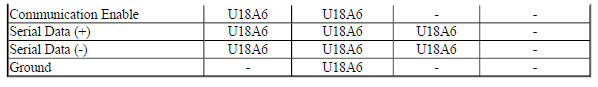
Circuit/System Description
The side object sensor modules use radar to determine the presence of objects nearby. The left side object sensor is the master that communicates on serial data. There is a private communication network between the left and right sensors. The scan tool can communicate only with the left sensor. Side blind zone alert is active when the vehicle is out of park or the parking brake is off on manual transmission vehicles. If a vehicle is detected in the side blind zone, the warning symbols will illuminate on the appropriate side. The warning symbols will vary brightness based on the ambient light conditions. When an object is detected in the left side blind zone, the side object sensor module sends a message to the right sensor through serial data. The right sensor then supplies voltage to illuminate the visual indicator on the left side outside rear view mirror. When an object is detected in the right side blind zone, the right side object sensor will supply a voltage to illuminate the visual indicator on the right side outside rear view mirror.
Conditions for Running the DTC
The system voltage is between 9-16 V.
Conditions for Setting the DTC
A supervised periodic message that includes the transmitter device availability has not been received.
Action Taken When the DTC Sets
Specific subsystems will not function.
Conditions for Clearing the DTC
- A current DTC clears when the malfunction is no longer present.
- A history DTC clears when the device ignition cycle counter reaches the reset threshold of 40, without a repeat of the malfunction.
Reference Information
Schematic Reference
- Object Detection Schematics (Encore) , Object Detection Schematics (Encore)
- Data Communication Schematics (Encore), Data Communication Schematics (Encore)
- Control Module References
Connector End View Reference
WIRING SYSTEMS AND POWER MANAGEMENT - COMPONENT CONNECTOR END VIEWS - INDEX - ENCORE WIRING SYSTEMS AND POWER MANAGEMENT - COMPONENT CONNECTOR END VIEWS - INDEX - Encore
Description and Operation
- Object Detection Description and Operation (Rearvision Camera, UVC) , Object Detection Description and Operation (Rear Park Assist, UD7) , Object Detection Description and Operation (Side Blind Zone Alert, UFT) , Object Detection Description and Operation (Rear Cross Traffic Alert, UFG)
- Data Link Communications Description and Operation
Electrical Information Reference
- Circuit Testing
- Connector Repairs
- Testing for Intermittent Conditions and Poor Connections
- Wiring Repairs
Scan Tool Reference
Control Module References for scan tool information
Circuit/System Verification
- Verify that DTC U0073, U0078, B1325, B1330, B1370, B1380, B1424, B1440, B1441, B1517, C0800, C0899, C12E1, P0560, or P0562 is not set.
If any of the DTCs are set
Refer to Diagnostic Trouble Code (DTC) List - Vehicle .
If none of the DTCs are set
- Refer to Circuit/System Testing.
Circuit/System Testing
NOTE: Use the schematics and connector end views to identify the device's ground, B+, and serial data circuit terminals.
- Ignition OFF, all access doors closed, all vehicle systems OFF, and all keys at least 3 m (9.8 ft) away from vehicle. It may take up to 2 min for all vehicle systems to power down. Disconnect the harness connector at the B218R Side Object Sensor Module - Right.
- Test for less than 10 ohms between each ground circuit terminal and ground.
If 10 ohms or greater
- Ignition OFF.
- Test for less than 2 ohms in the ground circuit end to end.
- If 2 ohms or greater, repair the open/high resistance in the circuit.
- If less than 2 ohms, repair the open/high resistance in the ground connection.
If less than 10 ohms
- Ignition ON.
- If equipped, verify a test lamp illuminates between each B+ circuit terminal and ground.
If the test lamp does not illuminate and the circuit fuse is good
- Ignition OFF.
- Test for less than 2 ohms in the B+ circuit end to end.
- If 2 ohms or greater, repair the open/high resistance in the circuit.
- If less than 2 ohms, verify the fuse is not open and there is voltage at the fuse.
If the test lamp does not illuminate and the circuit fuse is open
- Ignition OFF.
- Test for infinite resistance between the B+ circuit and ground.
- If less than infinite resistance, repair the short to ground on the circuit.
- If infinite resistance, replace the B218R Side Object Sensor Module - Right.
If the test lamp illuminates
- Ignition ON.
- If equipped, test for at least 6 V between the communication enable circuit terminal and ground.
If less than 6 V
- Ignition OFF, disconnect the harness connectors at the B218L Side Object Sensor Module - Left.
- Test for infinite resistance between the communication enable circuit terminal and ground.
- If less than infinite resistance, repair the short to ground on the circuit.
- If infinite resistance
- Test for less than 2 ohms in the communication enable circuit end to end.
- If 2 ohms or greater, repair the open/high resistance in the circuit.
- If less than 2 ohms, replace the B218L Side Object Sensor Module - Left.
If 6 V or greater
- Ignition OFF, all access doors closed, all vehicle systems OFF, and all keys at least 3 m (9.8 ft) away from vehicle. It may take up to 2 min for all vehicle systems to power down. Disconnect the harness connector at the B218L Side Object Sensor Module - Left.
- Test for less than 1 V between each serial data circuits and ground.
If 1 V or greater
Repair the short to voltage in the serial data circuit.
If less than 1 V
- Test for infinite resistance between each serial data circuits and ground.
If less than infinite resistance
Repair the short to ground in the serial data circuit.
If infinite resistance
- Test for infinite resistance between 2 serial data circuits.
If less than infinite resistance
Repair the short together between the serial data circuits.
If infinite resistance
- Test for less than 2 ohms in each of the serial data circuits end to end between the B218L Side Object Sensor Module - Left and the B218R Side Object Sensor Module - Right.
If 2 ohms or greater
Repair the open/high resistance in the serial data circuit.
If less than 2 ohms
- Replace the B218R Side Object Sensor Module - Right.
Repair Instructions
Perform the Diagnostic Repair Verification after completing the repair.
- GMLAN and Media Oriented Systems Transport (MOST) Wiring Repairs
- Control Module References for device replacement, programming and setup
DTC U18B9-U18BF: High speed can bus subnet configuration list
Diagnostic Instructions
- Perform the Diagnostic System Check - Vehicle prior to using this diagnostic procedure.
- Review Strategy Based Diagnosis for an overview of the diagnostic approach.
- Diagnostic Procedure Instructions provides an overview of each diagnostic category.
DTC Descriptor
DTC U18B9
Primary High Speed CAN Bus Subnet Configuration List
DTC U18BF
Secondary High Speed CAN Bus Subnet Configuration List
For symptom byte information, refer to Symptom Byte List .
Circuit/System Description
Devices on the high speed GMLAN serial data bus and the chassis high speed GMLAN serial data bus must be programmed with software that specifically identifies the correct type and quantity of devices on the bus based on RPO configuration. If a device was not properly configured after installation, the appropriate U Code may be set for that device. No external circuit diagnosis is involved.
Conditions for Running the DTC
- Voltage supplied to the device is in the normal operating voltage range.
- The vehicle power mode requires serial data communication to occur.
Conditions for Setting the DTC
- The device is not configured properly.
- Control unit recognises a programming error.
- CAN-Bus configuration is invalid
Conditions for Clearing the DTC
- A current DTC clears when the malfunction is no longer present.
- A history DTC clears when the device ignition cycle counter reaches the reset threshold, without a repeat of the malfunction.
Reference Information
Schematic Reference
- Data Communication Schematics (Encore), Data Communication Schematics (Encore)
- Control Module References
Connector End View Reference
WIRING SYSTEMS AND POWER MANAGEMENT - COMPONENT CONNECTOR END VIEWS - INDEX - ENCORE WIRING SYSTEMS AND POWER MANAGEMENT - COMPONENT CONNECTOR END VIEWS - INDEX - Encore
Description and Operation
Data Link Communications Description and Operation
Electrical Information Reference
- Circuit Testing
- Connector Repairs
- Testing for Intermittent Conditions and Poor Connections
- Wiring Repairs
Scan Tool Reference
Control Module References for scan tool information
Circuit/System Verification
- Ignition ON.
- Verify DTC U18B9-U18BF is not set.
- If DTC U18B9-U18BF is set along with other DTCs set
Diagnose all other DTCs first. Refer to Diagnostic Trouble Code (DTC) List - Vehicle .
- If DTC U18B9-U18BF is set without other DTCs set
- Program the device that set the DTC.
- Ignition OFF, remove the scan tool, open and close the driver door. Wait 60 s.
- Verify the DTC does not set.
- If the DTC sets, replace the appropriate device.
- If the DTC does not set
- All OK.
If DTC U18B9-U18BF is not set
- All OK
Repair Instructions
Perform the Diagnostic Repair Verification after completing the repair.
Control Module References for device replacement, programming and setup
DTC U2099: High speed communication enable circuit
Diagnostic Instructions
- Perform the Diagnostic System Check - Vehicle prior to using this diagnostic procedure.
- Review Strategy Based Diagnosis for an overview of the diagnostic approach.
- Diagnostic Procedure Instructions provides an overview of each diagnostic category.
DTC Descriptor
DTC U2099
High Speed Communication Enable Circuit
For symptom byte information, refer to Symptom Byte List
Diagnostic Fault Information
.jpg)
Circuit/System Description
The body control module (BCM) activates the ignition circuit, when the ignition key is in ACC, ON or START.
The ignition circuit wakes up the devices for serial data bus communication.
Conditions for Running the DTC
- The system voltage is between 9-16 V.
- The vehicle power mode master requires serial data communication to occur.
Conditions for Setting the DTC
The BCM senses a short to ground on the ignition circuit.
Action Taken When the DTC Sets
- The output command is turned off while the malfunction is present.
- The devices use a default value for the missing parameters until the next ignition cycle.
- The device(s) is never signaled. Therefore, the specific subsystem(s) will not function.
- The vehicle will not start while the circuit is shorted to ground.
Conditions for Clearing the DTC
- A current DTC clears when the malfunction is no longer present.
- A history DTC clears when the device ignition cycle counter reaches the reset threshold of 50, without a repeat of the malfunction.
Reference Information
Schematic Reference
- Data Communication Schematics (Encore), Data Communication Schematics (Encore)
- Control Module References
Connector End View Reference
WIRING SYSTEMS AND POWER MANAGEMENT - COMPONENT CONNECTOR END VIEWS - INDEX - ENCORE WIRING SYSTEMS AND POWER MANAGEMENT - COMPONENT CONNECTOR END VIEWS - INDEX - Encore
Description and Operation
Data Link Communications Description and Operation
Electrical Information Reference
- Circuit Testing
- Connector Repairs
- Testing for Intermittent Conditions and Poor Connections
- Wiring Repairs
Scan Tool Reference
Control Module References for scan tool information
Circuit/System Testing
NOTE: Use the schematic to determine which devices are on the K9 Body Control Module's ignition circuit terminal 23 X4. Use the connector end view to identify the ignition circuit terminal for each of those devices.
- Ignition OFF, disconnect the harness connectors at an easily accessible device that shares the K9 Body Control Module's ignition circuit terminal 23 X4. Ignition ON.
- Verify that the DTC U2099 remains current.
- If the DTC becomes history
Replace the device that was just disconnected.
If the DTC remains current
- With the prior devices disconnected, repeat steps 1 and 2 for each device on the ignition circuit except the K9 Body Control Module.
- Ignition OFF, disconnect the X4 harness connector at the K9 Body Control Module.
- 5. Test for infinite resistance between the ignition circuit terminal 23 X4 at the K9 Body Control Module and ground.
If less than infinite resistance
Repair the short to ground on the circuit.
If infinite resistance
- Replace the K9 Body Control Module.
Repair Instructions
Perform the Diagnostic Repair Verification after completing the repair.
- GMLAN and Media Oriented Systems Transport (MOST) Wiring Repairs
- Control Module References for device replacement, programming and setup
Symptoms - data communications
NOTE: The following steps must be completed before using the symptom tables.
- Perform the Diagnostic System Check - Vehicle before using the symptom tables in order to verify that all of the following are true:
- There are no Diagnostic Trouble Codes (DTC) set.
- The devices can communicate via the serial data links.
- Review the system operation in order to familiarize yourself with the system functions. Refer to Data Link Communications Description and Operation.
Visual/Physical Inspection
- Inspect for aftermarket devices which could affect the operation of the systems. Refer to Checking Aftermarket Accessories .
- Inspect the easily accessible or visible system components for obvious damage or conditions which could cause the symptom.
Intermittent
Faulty electrical connections or wiring may be the cause of intermittent conditions. Refer to Testing for Intermittent Conditions and Poor Connections .
Symptom List
Refer to a symptom diagnostic procedure from the following list in order to diagnose the symptom:
- Scan Tool Does Not Power Up
- Scan Tool Does Not Communicate with High Speed GMLAN Device
- Scan Tool Does Not Communicate with Low Speed GMLAN Device
SCAN TOOL DOES NOT POWER UP
Diagnostic Instructions
- Perform the Diagnostic System Check - Vehicle prior to using this diagnostic procedure.
- Review Strategy Based Diagnosis for an overview of the diagnostic approach.
- Diagnostic Procedure Instructions provides an overview of each diagnostic category.
Diagnostic Fault Information
.jpg)
Circuit/System Description
The data link connector (DLC) is a standardized 16 cavity connector. Connector design and location is dictated by an industry wide standard, and is required to provide the following:
- Scan tool B+ voltage at terminal 16
- Scan tool ground at terminal 4
- Common ground at terminal 5
Diagnostic Aids
- The scan tool will power up with the ignition OFF. Some devices however, will not communicate unless the ignition is ON and the power mode master device sends the appropriate power mode message.
- If the B+ circuit, ground circuits, and connections of the data link connector are functioning properly, the malfunction must be due to the scan tool.
Reference Information
Reference Information
- Data Communication Schematics (Encore), Data Communication Schematics (Encore)
- Control Module References
Connector End View Reference
WIRING SYSTEMS AND POWER MANAGEMENT - COMPONENT CONNECTOR END VIEWS - INDEX - ENCORE WIRING SYSTEMS AND POWER MANAGEMENT - COMPONENT CONNECTOR END VIEWS - INDEX - Encore
Description and Operation
Data Link Communications Description and Operation
Electrical Information Reference
- Circuit Testing
- Connector Repairs
- Testing for Intermittent Conditions and Poor Connections
- Wiring Repairs
Scan Tool Reference
Control Module References for scan tool information
Circuit/System Testing
- Ignition OFF, all access doors closed, all vehicle systems OFF, and all keys at least 3 m (9.8 ft) away from vehicle. It may take up to 2 minutes for all vehicle systems to power down.
- Test for less than 2 ohms between each of the X84 Data Link Connector ground circuit terminals listed below and ground.
- Ground circuit terminal 4
- Ground circuit terminal 5
If 2 ohms or greater
- Ignition OFF.
- Test for less than 2 ohms in the ground circuit end to end.
- If 2 ohms or greater, repair the open/high resistance in the circuit.
- If less than 2 ohms, repair the open/high resistance in the ground connection.
If less than 2 ohms
- Ignition ON.
- Verify a test lamp illuminates between the B+ circuit terminal 16 at the X84 Data Link Connector and ground.
If the test lamp does not illuminate and the circuit fuse is good
- Ignition OFF.
- Test for less than 2 ohms in the B+ circuit end to end.
- If 2 ohms or greater, repair the open/high resistance in the circuit.
- If less than 2 ohms, verify the fuse is not open and there is voltage at the fuse.
If the test lamp does not illuminate and the circuit fuse is open
- Ignition OFF.
- Test for infinite resistance between the B+ circuit and ground.
- If less than infinite resistance, repair the short to ground on the circuit.
If the test lamp illuminates
- Refer to the scan tool user guide.
Scan tool does not communicate with chassis high speed gmlan device
Diagnostic Instructions
- Perform the Diagnostic System Check - Vehicle prior to using this diagnostic procedure.
- Review Strategy Based Diagnosis for an overview of the diagnostic approach.
- Diagnostic Procedure Instructions provides an overview of each diagnostic category.
Diagnostic Fault Information
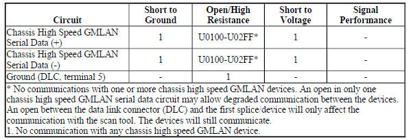
Circuit/System Description
The chassis high speed GMLAN bus functions the same as the primary high speed GMLAN bus, and the two buses operate in parallel. The chassis high speed GMLAN bus is added to reduce message congestion on the primary high speed bus. Since the chassis high speed GMLAN bus and primary high speed GMLAN bus operate in the same manner, the diagnostics for each are the same.
The serial data is transmitted on two twisted wires that allow speeds up to 500 kbit/s. The twisted pair is terminated with two 120 ohms resistors, one is internal to the electronic brake control module and the other can be a separate resistor in a connector assembly or in another device. The resistors are used as the load for the chassis high speed GMLAN bus during normal vehicle operation. The chassis high speed GMLAN is a differential bus. The chassis high speed GMLAN serial data bus (+) and chassis high speed GMLAN serial data (-) are driven to opposite extremes from a rest or idle level of approximately 2.5 V. Driving the lines to their extremes, adds 1 V to the chassis high speed GMLAN serial data bus (+) circuit and subtracts 1 V from the chassis high speed GMLAN serial data bus (-) circuit. If serial data is lost, devices will set a no communication code against the non-communicating device. Note that a loss of serial data DTC does not represent a failure of the device that set it.
Diagnostic Aids
- Sometimes, while diagnosing a specific customer concern or after a repair, you may notice a history UCircuit code present. However, there is no associated "current" or "active" status. Loss-of-communication Ucodes such as these can set for a variety of reasons. Many times, they are transparent to the vehicle operator and technician, and/or have no associated symptoms. Eventually, they will erase themselves automatically after a number of fault-free ignition cycles. This condition would most likely be attributed to one of these scenarios:
- A device on the data communication circuit was disconnected while the communication circuit is awake.
- Power to one or more devices was interrupted during diagnosis.
- A low battery condition was present, so some devices stop communicating when battery voltage drops below a certain threshold.
- Battery power was restored to the vehicle and devices on the communication circuit did not all reinitialize at the same time.
- If a loss-of-communication U code appears in history for no apparent reason, it is most likely associated with one of the scenarios above. These are all temporary conditions and should never be interpreted as an intermittent fault, causing you to replace a part.
- Do not replace a device reporting a U code. The U code identifies which device needs to be diagnosed for a communication issue.
- Communication may be available between some devices and the scan tool with one or more GMLAN serial data systems inoperative. This condition is due to those devices using multiple serial data communication systems.
- An open in the DLC ground circuit terminal 5 will allow the scan tool to operate but not communicate with the vehicle.
- Technicians may find various Local Area Network (LAN) communication Diagnostic Trouble Codes (DTC).
Reference Information
Schematic Reference
- Data Communication Schematics (Encore), Data Communication Schematics (Encore)
- Control Module References
Connector End View Reference
WIRING SYSTEMS AND POWER MANAGEMENT - COMPONENT CONNECTOR END VIEWS - INDEX - ENCORE WIRING SYSTEMS AND POWER MANAGEMENT - COMPONENT CONNECTOR END VIEWS - INDEX - Encore
Description and Operation
Data Link Communications Description and Operation
Electrical Information Reference
- Circuit Testing
- Connector Repairs
- Testing for Intermittent Conditions and Poor Connections
- Wiring Repairs
Scan Tool Reference
Control Module References for scan tool information
Circuit/System Verification
- Ignition ON.
- Verify two or more devices are not communicating on the chassis high
speed GMLAN serial data circuit.
Refer to Data Link References to determine how many devices should be communicating on the bus.
If only one device is not communicating
Refer to Circuit/System Testing - Testing the Device Circuits.
If two or more devices are not communicating
- Ignition OFF, all access doors closed, all vehicle systems OFF, and all keys at least 3 m (9.8 ft) away from vehicle. Disconnect the scan tool from the X84 Data Link Connector. The following tests will be done at the X84 Data Link Connector. It may take up to 2 minutes for all vehicle systems to power down.
- Test for less than 10 ohms between the ground circuit terminal 5 and ground.
If 10 ohms or greater
- Ignition OFF.
- Test for less than 2 ohms in the ground circuit end to end.
- If 2 ohms or greater, repair the open/high resistance in the circuit.
- If less than 2 ohms, repair the open/high resistance in the ground connection.
If less than 10 ohms
- Ignition ON.
- Test for less than 4.5 V between the serial data circuits listed below and ground.
- Terminal 12
- Terminal 13
If 4.5 V or greater
Refer to Circuit/System Testing - Testing the Serial Data Circuits for a Short to Voltage.
If less than 4.5 V
- Ignition OFF, all access doors closed, all vehicle systems OFF, and all keys at least 3 m (9.8 ft) away from vehicle. It may take up to 2 minutes for all vehicle systems to power down.
- Test for greater than 100 ohms between the serial data circuits listed below and ground.
- Terminal 12
- Terminal 13
If 100 ohms or less
Refer to Circuit/System Testing - Testing the Serial Data Circuits for a Short to Ground.
If greater than 100 ohms
- Test for 50-70 ohms between the serial data circuit terminals 12 and 13.
If less than 35 ohms
There may be a third terminating resistor between the serial data circuits. This can happen if the incorrect device is installed. Some devices are available with and without the terminating resistors installed to reduce the need of terminating resistors in the wiring harness. Refer to Circuit/System Testing - Testing the Serial Data Circuits for a Short between the Circuits.
If greater than 70 ohms but less than infinite
Refer to Circuit/System Testing - Testing the Serial Data Circuits for an Open/High Resistance
If infinite resistance
Repair the open/high resistance in the circuit between the X84 Data Link Connector and the first splice/device in the serial data circuit.
If between 50-70 ohms
- Refer to Circuit/System Testing - Testing the Device Circuits.
Circuit/System Testing
NOTE: Each device may need to be disconnected to isolate a circuit fault.
Use the schematic to identify the following:
- Chassis high speed GMLAN devices the vehicle is equipped with
- Chassis high speed GMLAN serial data circuit terminating resistors
- Device locations on the chassis high speed GMLAN serial data circuits
- Each device's ground, B+, ignition, and chassis high speed GMLAN serial data circuit terminals
Some devices with an internal terminating resistor have a loop in the harness that connects the internal terminating resistor to the serial data circuit. When wired this way, test these loop circuits for the appropriate failure mode short to voltage, short to ground, or open/high resistance prior to replacing the device for each of the following tests.
Testing the Serial Data Circuits for a Short to Voltage
- Ignition OFF, disconnect the harness connectors with the chassis high speed GMLAN serial data circuits at an easily accessible device, ignition ON.
- Test for greater than 4.5 V between each serial data circuit at the device connector that was just disconnected and ground.
If each serial data circuit is 4.5 V or less
- Ignition OFF.
- Test for less than 10 ohms between each of the device's ground circuit terminals and ground.
- If 10 ohms or greater, repair the open/high resistance in the circuit.
- If less than 10 ohms, replace the device that was disconnected.
If any serial data circuit is greater than 4.5 V
- Ignition OFF, disconnect the harness connectors with the chassis high speed GMLAN serial data circuits at another device, in the direction of the circuit shorted to voltage, ignition ON.
- Test for greater than 4.5 V between each serial data circuit at the device connector that was just disconnected and ground.
If each serial data circuit is 4.5 V or less
- Ignition OFF.
- Test for less than 10 ohms between each of the device's ground circuit terminals and ground.
- If 10 ohms or greater, repair the open/high resistance in the circuit.
- If less than 10 ohms, replace the device that was disconnected.
If any serial data circuit is greater than 4.5 V
- Repeat step 3 until one of the following conditions are isolated:
- A short to voltage on the serial data circuit between two devices or splice packs, if equipped.
- A short to voltage on the serial data circuit between a device and a terminating resistor.
Testing the Serial Data Circuits for a Short to Ground
- Ignition OFF, all access doors closed, all vehicle systems OFF, and all keys at least 3 m (9.8 ft) away from vehicle. It may take up to 2 minutes for all vehicle systems to power down.
- Disconnect the harness connectors with the chassis high speed GMLAN serial data circuits at an easily accessible device.
- Test for greater than 100 ohms between each serial data circuit at the device connector that was just disconnected and ground.
If each serial data circuit is 100 ohms or greater
Replace the device that was disconnected.
If any serial data circuit is less than 100 ohms
- Disconnect the harness connectors with the chassis high speed GMLAN serial data circuits at another device, in the direction of the circuit shorted to ground.
- Test for greater than 100 ohms between each serial data circuit at the device connector that was just disconnected and ground.
If both serial data circuits are 100 ohms or greater
Replace the device that was disconnected.
If any serial data circuit is less than 100 ohms
- Repeat step 4 until one of the following conditions are isolated:
- A short to ground on the serial data circuit between two devices or splice packs, if equipped.
- A short to ground on the serial data circuit between a device and a terminating resistor.
- A short to ground on the serial data circuit between the X84 Data Link Connector and the first device or splice pack.
Testing the Serial Data Circuits for a Short between the Circuits
- Ignition OFF, all access doors closed, all vehicle systems OFF, and all keys at least 3 m (9.8 ft) away from vehicle. It may take up to 2 minutes for all vehicle systems to power down.
- Disconnect the harness connectors with the chassis high speed GMLAN serial data circuits at an easily accessible device that is not communicating.
- Test for greater than 110 ohms between each pair of serial data circuits at the device connector that was just disconnected.
If each pair of serial data circuits is 110 ohms or greater
Replace the device that was disconnected.
If any pair of serial data circuits is less than 110 ohms
- Connect the harness connectors at the device that was disconnected.
- Disconnect the harness connectors with the chassis high speed GMLAN serial data circuits at another device, in the direction of the circuit shorted together.
- Test for greater than 110 ohms between each pair of serial data circuits at the device connector that was just disconnected.
If each pair of serial data circuits is 110 ohms or greater
Replace the device that was disconnected.
If any pair of serial data circuits is less than 110 ohms
- Repeat step 4 until one of the following conditions are isolated:
- Serial data circuits shorted together between two devices or splice packs, if equipped
- Serial data circuits shorted together between a device and a terminating resistor.
- Serial data circuits shorted together between the X84 Data Link Connector and the first device or splice pack.
- A shorted terminating resistor.
Testing the Serial Data Circuits for an Open/High Resistance
- Ignition OFF, all access doors closed, all vehicle systems OFF, and all keys at least 3 m (9.8 ft) away from vehicle. It may take up to 2 minutes for all vehicle systems to power down.
- Disconnect the harness connectors with the chassis high speed GMLAN serial data circuits at an easily accessible device that is not communicating.
- Test for less than 130 ohms between each pair of serial data circuits at the device connector that was just disconnected.
If each pair of serial data circuit is 130 ohms or less
Replace the device that was disconnected.
If any pair of serial data circuits is greater than 130 ohms
- Connect the harness connectors at the device that was disconnected.
- Disconnect the harness connectors with the chassis high speed GMLAN serial data circuits at another device, in the direction of the circuit with the open/high resistance.
- Test for less than 130 ohms between each pair of serial data circuits at the device connector that was just disconnected.
If each pair of serial data circuits is 130 ohms or less
Replace the device that was disconnected.
If any pair of serial data circuits is greater than 130 ohms
- Repeat step 4 until one of the following conditions are isolated:
- An open/high resistance on the serial data circuit between two devices or splice packs, if equipped.
- An open/high resistance on the serial data circuit between a device and a terminating resistor.
- An open/high resistance terminating resistor.
Testing the Device Circuits
- Ignition OFF, all access doors closed, all vehicle systems OFF, and all keys at least 3 m (9.8 ft) away from vehicle. It may take up to 2 minutes for all vehicle systems to power down.
- Disconnect the harness connectors at an easily accessible device that is not communicating.
- Test for less than 10 ohms between each ground circuit terminal and ground.
If 10 ohms or greater
- Ignition OFF.
- Test for less than 2 ohms in the ground circuit end to end.
- If 2 ohms or greater, repair the open/high resistance in the circuit.
- If less than 2 ohms, repair the open/high resistance in the ground connection.
If less than 10 ohms
- If equipped, verify a test lamp illuminates between each B+ circuit terminal and ground.
If the test lamp does not illuminate and the circuit fuse is good
- Ignition OFF.
- Test for less than 2 ohms in the B+ circuit end to end.
- If 2 ohms or greater, repair the open/high resistance in the circuit.
- If less than 2 ohms, verify the fuse is not open and there is voltage at the fuse.
If the test lamp does not illuminate and the circuit fuse is open
- Ignition OFF.
- Test for infinite resistance between the B+ circuit and ground.
- If less than infinite resistance, repair the short to ground on the circuit.
- If infinite resistance, replace the disconnected device.
If the test lamp illuminates
- Ignition ON.
- If equipped, verify a test lamp illuminates between each ignition circuit terminal, which has a fuse in the circuit, and ground.
If the test lamp does not illuminate and the circuit fuse is good
- Ignition OFF.
- Test for less than 2 ohms in the ignition circuit end to end.
- If 2 ohms or greater, repair the open/high resistance in the circuit.
- If less than 2 ohms, verify the fuse is OK and there is voltage at the fuse.
If the test lamp does not illuminate and the circuit fuse is open
- Ignition OFF.
- Test for infinite resistance between the ignition circuit and ground.
- If less than infinite resistance, repair the short to ground on the circuit.
- If infinite resistance, replace the disconnected device.
If the test lamp illuminates
- If equipped, verify a test lamp illuminates between each ignition circuit terminal, which is controlled by a control module, and ground.
If the test lamp does not illuminate
- Ignition OFF, disconnect the harness connectors at the control module that controls the ignition circuit.
- Test for infinite resistance between the ignition circuit and ground.
- If less than infinite resistance, repair the short to ground on the circuit.
- If infinite resistance
- Test for less than 2 ohms in the ignition circuit end to end.
- If 2 ohms or greater, repair the open/high resistance in the circuit.
- If less than 2 ohms, replace the control module that controls the ignition circuit.
If the test lamp illuminates
- Ignition OFF, all access doors closed, all vehicle systems OFF, and all keys at least 3 m (9.8 ft) away from vehicle. It may take up to 2 minutes for all vehicle systems to power down.
- Test for less than 130 ohms between each pair of chassis high speed GMLAN serial data circuits at the device connector that was just disconnected.
If any pair of serial data circuits is greater than 130 ohms
Repair the open/high resistance in the serial data circuits between the disconnected device and the circuit splice in the serial data circuits.
If each pair of serial data circuits is 130 ohms or less
- Replace the device that was disconnected.
Repair Instructions
Perform the Diagnostic Repair Verification after completing the repair.
- GMLAN and Media Oriented Systems Transport (MOST) Wiring Repairs
- Control Module References for device replacement, programming and setup
Scan tool does not communicate with high speed gmlan device
Diagnostic Instructions
- Perform the Diagnostic System Check - Vehicle prior to using this diagnostic procedure.
- Review Strategy Based Diagnosis for an overview of the diagnostic approach.
- Diagnostic Procedure Instructions provides an overview of each diagnostic category.
Diagnostic Fault Information
.jpg)

Circuit/System Description
The serial data is transmitted on two twisted wires that allow speeds up to 500 Kb/s. The twisted pair is terminated with two 120 ohms resistors, one is internal to the engine control module (ECM) and the other can be a separate resistor in a connector assembly or in another device. The resistors are used as the load for the High Speed GMLAN bus during normal vehicle operation. The high speed GMLAN is a differential bus. The high speed GMLAN serial data bus (+) and high speed GMLAN serial data (-) are driven to opposite extremes from a rest or idle level of approximately 2.5 V. Driving the lines to their extremes, adds 1 V to the high speed GMLAN serial data bus (+) circuit and subtracts 1 V from the high speed GMLAN serial data bus (-) circuit. If serial data is lost, devices will set a no communication code against the non-communicating device. Note that a loss of serial data DTC does not represent a failure of the device that set it.
Diagnostic Aids
Sometimes, while diagnosing a specific customer concern or after a repair, you may notice a history Ucode present. However, there is no associated "current" or "active" status. Loss-of-communication Ucodes such as these can set for a variety of reasons. Many times, they are transparent to the vehicle operator and technician, and/or have no associated symptoms. Eventually, they will erase themselves automatically after a number of fault-free ignition cycles. This condition would most likely be attributed to one of these scenarios:
- A device on the data communication circuit was disconnected while the communication circuit is awake.
- Power to one or more devices was interrupted during diagnosis.
- A low battery condition was present, so some devices stop communicating when battery voltage drops below a certain threshold.
- Battery power was restored to the vehicle and devices on the communication circuit did not all reinitialize at the same time.
- If a loss-of-communication U-code appears in history for no apparent reason, it is most likely associated with one of the scenarios above. These are all temporary conditions and should never be interpreted as an intermittent fault, causing you to replace a part.
Do not replace a device reporting a U code. The U code identifies which device needs to be diagnosed for a communication issue.
Communication may be available between some devices and the scan tool with the high speed GMLAN serial data system inoperative. This condition is due to those devices using multiple serial data communication systems.
An open in the DLC ground circuit terminal 5 will allow the scan tool to operate but not communicate with the vehicle.
The engine will not start when there is a total malfunction of the high speed GMLAN serial data bus.
Technicians may find various Local Area Network (LAN) communication Diagnostic Trouble Codes (DTC) and no low speed GMLAN communications with the scan tool.
These conditions may be caused by the installation of an aftermarket navigation radio module (see bulletins). Some customers may comment of one or more of the following concerns:
- Vehicle will not crank
- Vehicle cranks but will not start
- Vehicle stability enhancement system warning lights and messages
- PRNDL gear indicator position errors
Reference Information
Schematic Reference
- Data Communication Schematics (Encore), Data Communication Schematics (Encore)
- Control Module References
Connector End View Reference
WIRING SYSTEMS AND POWER MANAGEMENT - COMPONENT CONNECTOR END VIEWS - INDEX - ENCORE WIRING SYSTEMS AND POWER MANAGEMENT - COMPONENT CONNECTOR END VIEWS - INDEX - Encore
Description and Operation
Data Link Communications Description and Operation
Electrical Information Reference
- Circuit Testing
- Connector Repairs
- Testing for Intermittent Conditions and Poor Connections
- Wiring Repairs
Scan Tool Reference
Control Module References for scan tool information
Circuit/System Verification
- Ignition ON.
- Verify two or more devices are not communicating on the high speed GMLAN serial data circuit. Refer to Data Link References to determine how many devices should be communicating on the bus.
- If only one device is not communicating
Refer to Circuit/System Testing - Testing the Device Circuits.
- If two or more devices are not communicating
- Ignition OFF, all access doors closed, all vehicle systems OFF, and all keys at least 3 meters (9.8 feet) away from vehicle. Disconnect the scan tool from the X84 data link connector. The following tests will be done at the X84 data link connector. It may take up to 2 minutes for all vehicle systems to power down.
- Test for less than 10 ohms between the ground circuit terminal 5 and ground.
If 10 ohms or greater
- Ignition OFF.
- Test for less than 2 ohms in the ground circuit end to end.
- If 2 ohms or greater, repair the open/high resistance in the circuit.
- If less than 2 ohms, repair the open/high resistance in the ground connection.
If less than 10 ohms
- Ignition ON.
- Test for less than 4.5 V between the serial data circuits listed below and ground.
- Terminal 6
- Terminal 14
If 4.5 V or greater
Refer to Circuit/System Testing - Testing the Serial Data Circuits for a Short to Voltage.
If less than 4.5 V
- Ignition OFF, all access doors closed, all vehicle systems OFF, and all keys at least 3 meters (9.8 feet) away from vehicle. It may take up to 2 minutes for all vehicle systems to power down.
- Test for greater than 100 ohms between the serial data circuits listed below and ground.
- Terminal 6
- Terminal 14
If 100 ohms or less
Refer to Circuit/System Testing - Testing the Serial Data Circuits for a Short to Ground.
If greater than 100 ohms
- Test for 50-70 ohms between the serial data circuit terminals 6 and 14.
If less than 35 ohms
Refer to Circuit/System Testing - Testing the Serial Data Circuits for a Short between the Circuits.
If between 35-50 ohms
There may be a third terminating resistor between the serial data circuits. This can happen if the incorrect device is installed. Some devices are available with and without the terminating resistors installed to reduce the need of terminating resistors in the wiring harness. Refer to Circuit/System Testing - Testing the Serial Data Circuits for a Short between the Circuits.
If greater than 70 ohms but less than infinite
Refer to Circuit/System Testing - Testing the Serial Data Circuits for an Open/High Resistance.
If infinite resistance
Repair the open/high resistance in the circuit between the X84 data link connector and the first splice/device in the serial data circuit.
If between 50-70 ohms
- Refer to Circuit/System Testing - Testing the Device Circuits.
Circuit/System Testing
NOTE: Each device may need to be disconnected to isolate a circuit fault.
Use the schematic to identify the following:
- High speed GMLAN devices the vehicle is equipped with
- High speed GMLAN serial data circuit terminating resistors
- Device locations on the high speed GMLAN serial data circuits
- Each device's ground, B+, ignition, and high speed GMLAN serial data circuit terminals
Some devices with an internal terminating resistor have a loop in the harness that connects the internal terminating resistor to the serial data circuit. When wired this way, test these loop circuits for the appropriate failure mode short to voltage, short to ground, or open/high resistance prior to replacing the device for each of the following tests.
Testing the Serial Data Circuits for a Short to Voltage
- Ignition OFF, disconnect the harness connectors with the high speed GMLAN serial data circuits at an easily accessible device, ignition ON.
- Test for greater than 4.5 V between each serial data circuit at the device connector that was just disconnected and ground.
If each serial data circuit is 4.5 V or less
- Ignition OFF.
- Test for less than 10 ohms between each of the device's ground circuit terminals and ground.
- If 10 ohms or greater, repair the open/high resistance in the circuit.
- If less than 10 ohms, replace the device that was disconnected.
If any serial data circuit is greater than 4.5 V
- Ignition OFF, disconnect the harness connectors with the high speed GMLAN serial data circuits at another device, in the direction of the circuit shorted to voltage, ignition ON.
- Test for greater than 4.5 V between each serial data circuit at the device connector that was just disconnected and ground.
If each serial data circuit is 4.5 V or less
- Ignition OFF.
- Test for less than 10 ohms between each of the device's ground circuit terminals and ground.
- If 10 ohms or greater, repair the open/high resistance in the circuit.
- If less than 10 ohms, replace the device that was disconnected.
If any serial data circuit is greater than 4.5 V
- Repeat step 3 until one of the following conditions are isolated:
- A short to voltage on the serial data circuit between two devices or splice packs, if equipped.
- A short to voltage on the serial data circuit between a device and a terminating resistor.
Testing the Serial Data Circuits for a Short to Ground
- Ignition OFF, all access doors closed, all vehicle systems OFF, and all keys at least 3 meters (9.8 feet) away from vehicle. It may take up to 2 minutes for all vehicle systems to power down.
- Disconnect the harness connectors with the high speed GMLAN serial data circuits at an easily accessible device.
- Test for greater than 100 ohms between each serial data circuit at the device connector that was just disconnected and ground.
If each serial data circuit is 100 ohms or greater
Replace the device that was disconnected.
If any serial data circuit is less than 100 ohms
- Disconnect the harness connectors with the high speed GMLAN serial data circuits at another device, in the direction of the circuit shorted to ground.
- Test for greater than 100 ohms between each serial data circuit at the device connector that was just disconnected and ground.
If both serial data circuits are 100 ohms or greater
Replace the device that was disconnected.
If any serial data circuit is less than 100 ohms
- Repeat step 4 until one of the following conditions are isolated:
- A short to ground on the serial data circuit between two devices or splice packs, if equipped.
- A short to ground on the serial data circuit between a device and a terminating resistor.
- A short to ground on the serial data circuit between the X84 data link connector and the first device or splice pack.
Testing the Serial Data Circuits for a Short between the Circuits
- Ignition OFF, all access doors closed, all vehicle systems OFF, and all keys at least 3 meters (9.8 feet) away from vehicle. It may take up to 2 minutes for all vehicle systems to power down.
- Disconnect the harness connectors with the high speed GMLAN serial data circuits at an easily accessible device that is not communicating.
- Test for greater than 110 ohms between each pair of serial data circuits at the device connector that was just disconnected.
If each pair of serial data circuits is 110 ohms or greater
Replace the device that was disconnected.
If any pair of serial data circuits is less than 110 ohms
- Connect the harness connectors at the device that was disconnected.
- Disconnect the harness connectors with the high speed GMLAN serial data circuits at another device, in the direction of the circuit shorted together.
- Test for greater than 110 ohms between each pair of serial data circuits at the device connector that was just disconnected.
If each pair of serial data circuits is 110 ohms or greater
Replace the device that was disconnected.
If any pair of serial data circuits is less than 110 ohms
- Repeat step 4 until one of the following conditions are isolated:
- Serial data circuits shorted together between two devices or splice packs, if equipped.
- Serial data circuits shorted together between a device and a terminating resistor.
- Serial data circuits shorted together between the X84 data link connector and the first device or splice pack.
- A shorted terminating resistor.
Testing the Serial Data Circuits for an Open/High Resistance
- Ignition OFF, all access doors closed, all vehicle systems OFF, and all keys at least 3 meters (9.8 feet) away from vehicle. It may take up to 2 minutes for all vehicle systems to power down.
- Disconnect the harness connectors with the high speed GMLAN serial data circuits at an easily accessible device that is not communicating.
- Test for less than 130 ohms between each pair of serial data circuits at the device connector that was just disconnected.
If each pair of serial data circuits is 130 ohms or less
Replace the device that was disconnected.
If any pair of serial data circuits is greater than 130 ohms
- Connect the harness connectors at the device that was disconnected.
- Disconnect the harness connectors with the high speed GMLAN serial data circuits at another device, in the direction of the circuit with the open/high resistance.
- Test for less than 130 ohms between each pair of serial data circuits at the device connector that was just disconnected.
If each pair of serial data circuits is 130 ohms or less
Replace the device that was disconnected.
If any pair of serial data circuits is greater than 130 ohms
- Repeat step 4 until one of the following conditions are isolated:
- An open/high resistance on the serial data circuit between two devices or splice packs, if equipped.
- An open/high resistance on the serial data circuit between a device and a terminating resistor.
- An open/high resistance terminating resistor.
Testing the Device Circuits
- Ignition OFF, all access doors closed, all vehicle systems OFF, and all keys at least 3 meters (9.8 feet) away from vehicle. It may take up to 2 minutes for all vehicle systems to power down.
- Disconnect the harness connectors at an easily accessible device that is not communicating.
- Test for less than 10 ohms between each ground circuit terminal and ground.
If 10 ohms or greater
- Ignition OFF.
- Test for less than 2 ohms in the ground circuit end to end.
- If 2 ohms or greater, repair the open/high resistance in the circuit.
- If less than 2 ohms, repair the open/high resistance in the ground connection.
If less than 10 ohms
- If equipped, verify a test lamp illuminates between each B+ circuit terminal and ground.
If the test lamp does not illuminate and the circuit fuse is good
- Ignition OFF.
- Test for less than 2 ohms in the B+ circuit end to end.
- If 2 ohms or greater, repair the open/high resistance in the circuit.
- If less than 2 ohms, verify the fuse is not open and there is voltage at the fuse.
If the test lamp does not illuminate and the circuit fuse is open
- Ignition OFF.
- Test for infinite resistance between the B+ circuit and ground.
- If less than infinite resistance, repair the short to ground on the circuit.
- If infinite resistance, replace the disconnected device.
If the test lamp illuminates
- Ignition ON.
- If equipped, verify a test lamp illuminates between each ignition circuit terminal, which has a fuse in the circuit, and ground.
If the test lamp does not illuminate and the circuit fuse is good
- Ignition OFF.
- Test for less than 2 ohms in the ignition circuit end to end.
- If 2 ohms or greater, repair the open/high resistance in the circuit.
- If less than 2 ohms, verify the fuse is OK and there is voltage at the fuse.
If the test lamp does not illuminate and the circuit fuse is open
- Ignition OFF.
- Test for infinite resistance between the ignition circuit and ground.
- If less than infinite resistance, repair the short to ground on the circuit.
- If infinite resistance, replace the disconnected device.
If the test lamp illuminates
- If equipped, verify a test lamp illuminates between each ignition circuit terminal, which is controlled by a control module, and ground.
If the test lamp does not illuminate
- Ignition OFF, disconnect the harness connectors at the control module that controls the ignition circuit.
- Test for infinite resistance between the ignition circuit and ground.
- If less than infinite resistance, repair the short to ground on the circuit.
- If infinite resistance
- Test for less than 2 ohms in the ignition circuit end to end.
- If 2 ohms or greater, repair the open/high resistance in the circuit.
- If less than 2 ohms, replace the control module that controls the ignition circuit
If the test lamp illuminates
- Ignition OFF, all access doors closed, all vehicle systems OFF, and all keys at least 3 meters (9.8 feet) away from vehicle. It may take up to 2 minutes for all vehicle systems to power down.
- Test for less than 130 ohms between each pair of high speed GMLAN serial data circuits at the device connector that was just disconnected.
If any pair of serial data circuits is greater than 130 ohms
Repair the open/high resistance in the serial data circuits between the disconnected device and the circuit splice in the serial data circuits.
If each pair of serial data circuits is 130 ohms or less
- Replace the device that was disconnected.
Repair Instructions
Perform the Diagnostic Repair Verification after completing the repair.
- GMLAN and Media Oriented Systems Transport (MOST) Wiring Repairs
- Control Module References for device replacement, programming and setup
Scan tool does not communicate with low speed gmlan device
Diagnostic Instructions
- Perform the Diagnostic System Check - Vehicle prior to using this diagnostic procedure.
- Review Strategy Based Diagnosis for an overview of the diagnostic approach.
- Diagnostic Procedure Instructions provides an overview of each diagnostic category.
Diagnostic Fault Information
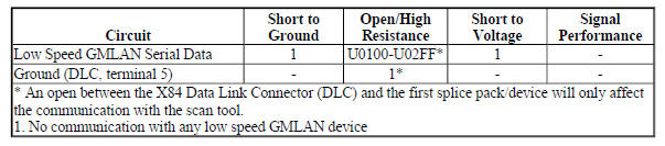
Circuit/System Description
The serial data is transmitted over a single wire to the appropriate devices. The transmission speed for GMLAN low speed is up to 83.33 kbit/s. Under normal vehicle operating conditions, the speed of the bus is 33.33 kbit/s.
The devices toggle the serial data circuit between 0-5 V during normal communications. To wake the devices connected to the low speed GMLAN serial data circuit, a voltage wake up pulse of 10 V is sent out. If serial data is lost, devices will set a no communication code against the non-communicating device. A loss of serial data communications DTC does not represent a failure of the device that set it.
Diagnostic Aids
Sometimes, while diagnosing a specific customer concern or after a repair, you may notice a history U code present. However, there is no associated "current" or "active" status. Loss of communication U codes such as these can set for a variety of reasons. Many times, they are transparent to the vehicle operator and technician, and/or have no associated symptoms. Eventually, they will erase themselves automatically after a number of fault-free ignition cycles. This condition would most likely be attributed to one of these scenarios:
- A device on the data communication circuit was disconnected while the communication circuit is awake.
- Power to one or more devices was interrupted during diagnosis
- A low battery condition was present, so some devices stop communicating when battery voltage drops below a certain threshold.
- Battery power was restored to the vehicle and devices on the communication circuit did not all re- initialize at the same time.
- If a loss of communication U- code appears in history for no apparent reason, it is most likely associated with one of the scenarios above. These are all temporary conditions and should never be interpreted as an intermittent fault, causing you to replace a part.
Do not replace a device reporting a U code. The U code identifies which device needs to be diagnosed for a communication issue.
Communication may be available between the device and the scan tool with the low speed GMLAN serial data system inoperative. This condition is due to the device using both the high and low speed GMLAN systems.
An open in the low speed GMLAN serial data circuit between the splice pack and a device will only affect that specific device. This type of failure will set a loss of communication DTC for each device affected, and the other devices will still communicate.
An open in the X84 Data Link Connector (DLC) ground circuit terminal 5 will allow the scan tool to operate but not communicate with the vehicle.
The engine may not start when there is a total malfunction of the low speed GMLAN serial data circuit.
Technicians may find various Local Area Network (LAN) communication Diagnostic Trouble Codes (DTC) and no low speed LAN communications with the scan tool.
These conditions may be caused by the installation of an aftermarket navigation radio device (see bulletins). Some customers may comment of one or more of the following concerns:
- Vehicle will not crank
- Vehicle cranks but will not start
- Vehicle stability enhancement system warning lights and messages
- PRNDL gear indicator position errors
Reference Information
Schematic Reference
- Data Communication Schematics (Encore), Data Communication Schematics (Encore)
- Control Module References
Connector End View Reference
WIRING SYSTEMS AND POWER MANAGEMENT - COMPONENT CONNECTOR END VIEWS - INDEX - ENCORE WIRING SYSTEMS AND POWER MANAGEMENT - COMPONENT CONNECTOR END VIEWS - INDEX - Encore
Description and Operation
Data Link Communications Description and Operation
Electrical Information Reference
- Circuit Testing
- Connector Repairs
- Testing for Intermittent Conditions and Poor Connections
- Wiring Repairs
Scan Tool Reference
Control Module References for scan tool information
Circuit/System Verification
NOTE: Use the schematic to identify the following:
- Devices the vehicle is equipped with
- Device and splice pack locations on the low speed GMLAN serial data circuit
- The low speed GMLAN serial data circuit terminals for each device or splice pack
- Attempt to communicate with all devices on the low speed GMLAN serial data circuit. Refer to Data Link References.
- Verify which devices are communicating on the low speed GMLAN serial data circuit.
If only one device is not communicating
Diagnose that device only. Refer to DTC U0100-U02FF.
If one or more devices are communicating but not all
Refer to Circuit/System Testing - Testing the Serial Data Circuit for an Open/High Resistance.
If none of the devices are communicating
- Ignition OFF, all access doors closed, all vehicle systems OFF, all keys at least 3 m (9.8 ft) away from vehicle. Disconnect the scan tool from the X84 Data Link Connector. The following tests will be done at the X84 Data Link Connector. It may take up to 2 minutes for all vehicle systems to power down.
- Test for less than 10 ohms between the ground circuit terminal 5 and ground.
If 10 ohms or greater
- Ignition OFF.
- Test for less than 2 ohms in the ground circuit end to end.
- If 2 ohms or greater, repair the open/high resistance in the circuit.
- If less than 2 ohms, repair the open/high resistance in the ground connection.
If less than 10 ohms
- Ignition ON.
- Test for less than 4.5 V between the serial data circuit terminal 1 and ground.
If 4.5 V or greater
Refer to Circuit/System Testing - Testing the Serial Data Circuits for a Short to Voltage.
If less than 4.5 V
- Ignition OFF, all access doors closed, all vehicle systems OFF, all keys at least 3 m (9.8 ft) away from vehicle. It may take up to 2 minutes for all vehicle systems to power down.
- Test for greater than 100 ohms between the serial data circuit terminal 1 and ground.
If 100 ohms or less
Refer to Circuit/System Testing - Testing the Serial Data Circuits for a Short to Ground.
If greater than 100 ohms
- Disconnect the appropriate harness connector at the first splice pack closest in the circuit to the X84 Data Link Connector.
- Test for less than 2 ohms between the X84 Data Link Connector's serial data circuit terminal 1 and the splice pack harness connector's serial data input terminal.
If 2 ohms or greater
Repair the open/high resistance in the serial data circuit.
If less than 2 ohms
- Replace the splice pack.
Circuit/System Testing
Testing the Serial Data Circuits for a Short to Voltage
- Ignition OFF, disconnect the appropriate harness connectors at all low speed GMLAN serial data splice packs, ignition ON.
- Test for less than 4.5 V between the serial data circuit terminal 1 at the X84 Data Link Connector and ground.
If 4.5 V or greater
Repair the short to voltage on the serial data circuit.
If less than 4.5 V
- Test for less than 4.5 V between each low speed GMLAN serial data circuit at a splice pack and ground.
If any serial data circuit is greater than 4.5 V
- Ignition OFF, disconnect all devices on the failed serial data circuit, ignition ON.
- Test for less than 1 V between each section of the failed serial data circuit and ground.
- If 1 V or greater, repair the short to voltage in the circuit
- If less than 1 V
- Connect the splice pack and connect the first device on the failed serial data circuit, ignition ON.
- Verify the scan tool communicates or not with the low speed GMLAN serial data circuit.
- the scan tool does not communicate, replace the device that was just connected.
- If the scan tool communicates and there are more devices to connect, connect the next device and repeat step 3.4.
- If the scan tool communicates and there are no more devices to connect
- All OK.
If all serial data circuits are less than 4.5 V
- All OK.
Testing the Serial Data Circuits for a Short to Ground
- Ignition OFF, all access doors closed, all vehicle systems OFF, and all keys at least 3 m (9.8 ft) away from vehicle. Disconnect the appropriate harness connectors at all low speed GMLAN serial data splice packs.
- Test for infinite resistance between the serial data circuit terminal 1 at the X84 Data Link Connector and ground.
If less than infinite resistance
Repair the short to ground on the serial data circuit.
If infinite resistance
- Test for greater than 100 ohms between each low speed GMLAN serial data circuit at a splice pack and ground.
If any serial data circuit is 100 ohms or less
- Disconnect all devices on the failed serial data circuit.
- Test for infinite resistance between each section of the failed serial data circuit and ground.
- If less than infinite resistance, repair the short to ground in the circuit.
- If infinite resistance
- Connect the splice pack and connect the first device on the failed serial data circuit, ignition ON.
- Verify the scan tool communicates or not with the low speed GMLAN serial data circuit.
- If the scan tool does not communicate, replace the device that was just connected.
- If the scan tool communicates and there are more devices to connect, connect the next device and repeat step 3.4.
- If the scan tool communicates and there are no more devices to connect
- All OK.
If all serial data circuits are greater than 100 ohms
- All OK.
Testing the Serial Data Circuit for an Open/High Resistance
- Ignition OFF and all vehicle systems OFF, disconnect the splice pack containing the devices that are not communicating on the low speed GMLAN serial data circuit.
- Test for less than 2 ohms between the X84 Data Link Connector terminal 1 and the disconnected splice pack.
If 2 ohms or greater
Repair the open/high resistance in the serial data circuit.
If less than 2 ohms
- Disconnect all devices on the failed serial data circuit.
- Test for less than 2 ohms between each section of the failed serial data circuit end to end.
If 2 ohms or greater
Repair the open/high resistance in the serial data circuit.
If less than 2 ohms
- Connect the splice pack and connect the first device on the failed serial data circuit.
- Verify if the device communicates or not with the scan tool.
If the device does not communicates
Replace the device.
If the device communicates and there are more devices to connect
Connect the next device on the failed serial data circuit and repeat step 6.
If all devices are connected and communicating
- All OK.
Repair Instructions
Perform the Diagnostic Repair Verification after completing the repair.
- GMLAN and Media Oriented Systems Transport (MOST) Wiring Repairs
- Control Module References for device replacement, programming and setup
Data link references
This table identifies which serial data link that a particular device uses for in-vehicle data transmission. Some devices may use more than one data link to communicate. Some devices may have multiple communication circuits passing through them without actively communicating on that data link. This table is used to assist in correcting a communication malfunction. Not all devices listed will be applicable to all vehicles. Refer to the schematics to determine which devices apply. For the description and operation of these serial data communication circuits, refer to Data Link Communications Description and Operation.
Data Link References
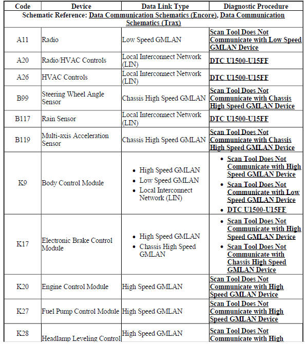
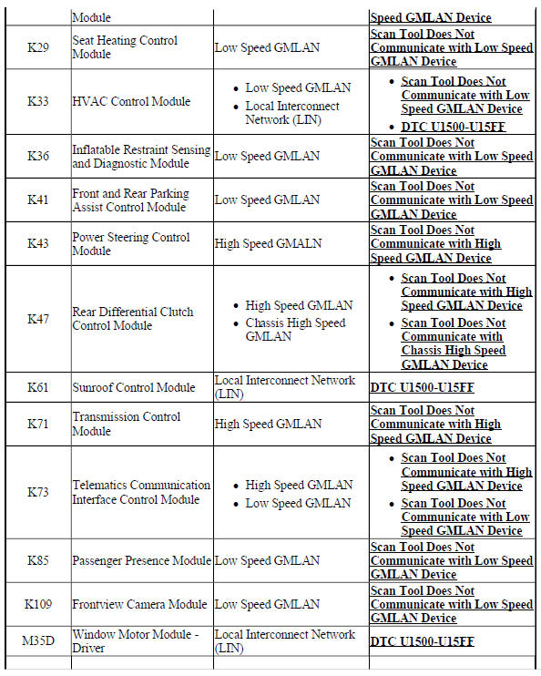
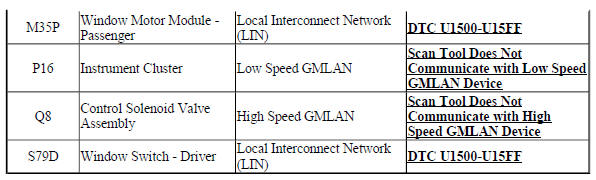
Repair instructions
BODY CONTROL MODULE REPLACEMENT (ENCORE)
.gif)
Fig. 21: Body Control Module
Body Control Module Replacement (Encore)
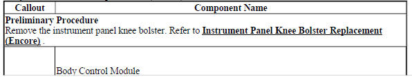
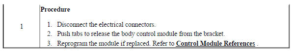
BODY CONTROL MODULE REPLACEMENT (Encore)
Fig. 22: Body Control Module
Body Control Module Replacement (Encore)
.jpg)
READ NEXT:
 Data communications - Description and operation
BODY CONTROL SYSTEM DESCRIPTION AND OPERATION
The body control system consists of the body control module (BCM),
communications, and various input and
outputs. Some inputs, outputs and messages requi
Floor Coverings and Headlinings - Repair instructions
Eliminating unwanted odors in vehicles
SPECIFICATIONS
ADHESIVES, FLUIDS, LUBRICANTS, AND SEALERS
Adhesives, Fluids, Lubricants, and Sealers
REPAIR INSTRUCTIONS
ELIMINATING UNWANTED ODORS IN VEHICLES
SEE MORE:
Manual Transmission Trouble Shooting
NOTE: This is GENERAL information. This article is not intended to
be specific to any
unique situation or individual vehicle configuration. For model-specific
information see appropriate articles where available.
INTRODUCTION
NOTE: This is GENERAL information. This article is not intended to
be sp
Schematic wiring diagrams
SPECIFICATIONS
FASTENER TIGHTENING SPECIFICATIONS
Fastener Tightening Specifications
SCHEMATIC WIRING DIAGRAMS
MOVEABLE WINDOW WIRING SCHEMATICS (ENCORE)
Front Windows
Fig. 1: Front Windows
Rear Windows
Fig. 2: Rear Windows
MOVEABLE WINDOW WIRING SCHEMATICS (Encore)
Front and Rear Power Window
