Buick Encore: Floor Coverings and Headlinings - Repair instructions
Eliminating unwanted odors in vehicles
SPECIFICATIONS
ADHESIVES, FLUIDS, LUBRICANTS, AND SEALERS
Adhesives, Fluids, Lubricants, and Sealers

REPAIR INSTRUCTIONS
ELIMINATING UNWANTED ODORS IN VEHICLES
GM Vehicle Care Odor Eliminator, Refer to Adhesives, Fluids, Lubricants, and Sealers , may control or eliminate odors in the interior and luggage compartment areas of GM vehicles. This non-toxic, biodegradable, odorless product has been shown to greatly reduce or remove the following types of odor:
- Objectionable smells of mold and mildew resulting from vehicle water leaks
- Customer created odors, such as smoke
You may safely use GM Vehicle Care Odor Eliminator on fabrics, vinyl, leather, carpet, and sound deadening materials. You may also induce this product into HVAC modules and instrument panel ducts for the control of non-bacterial related odors.
NOTE: This product leaves no residual scent and should not be used as an air freshener.
This product may result in the permanent elimination of an odor and may be preferable to customers whose allergies make them sensitive to perfumes. This product may effectively remove odors when directly contacting the odor source. In cases such as water leaks, use this product with diagnostic procedures to first eliminate the primary cause of the odor. Then use further applications on the residual odor to permanently correct the vehicle condition.
How to Use this Product
- Spray GM Vehicle Care Odor Eliminator directly or as an additive with carpet shampoo in steam cleaners.
- Do not use on any interior surface that plain water would deteriorate, because this product will have the same effect. Also avoid letting this product come into contact with vinegar or any acidic substance. Acidbased products will hamper the effectiveness of GM Vehicle Care Odor Eliminator.
- Complete eight page treatment sheets are enclosed within each case of GM Vehicle Care Odor Eliminator. These treatment instructions range from simple vehicle odor elimination to full step by step procedures for odor removal from water leaks.
- Instructions and cautions are printed on the bottle, but additional help is available. If you encounter a persistent or recurring odor, you may call to obtain additional information and usage suggestions.
FLOOR CARPET DRYING
If the carpet or the pad or insulator is wet, use the following criteria for drying or for replacing the components:
- For a 1-piece carpet assembly bonded to a cotton or a fiber padding, replace the entire assembly.
- For a 2-piece carpet assembly with a cotton or a fiber padding, replace the padding only. While the carpet is out of the vehicle, dry the carpet using the method described below.
- For a 1-piece carpet assembly bonded to a foam padding or attached to a synthetic padding, dry the carpet using the method described below.
- For a 2-piece carpet assembly with a synthetic padding, dry the assembly using the method described below.
Drying Method
- If you observe puddles of liquid on the carpet face, use a wet vacuum to remove the excess moisture.
- Blot the face of the carpet with a towel in order to absorb as much moisture as possible.
- Point a fan at the affected area and air dry the carpet.
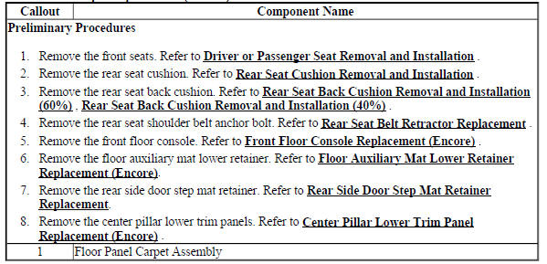
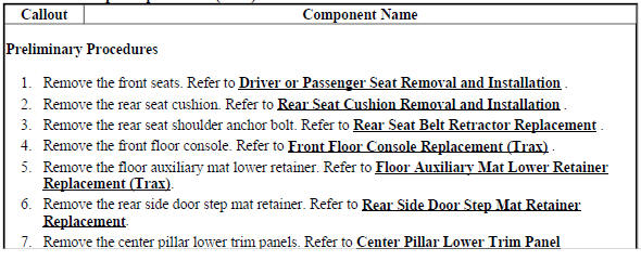
FLOOR PANEL CARPET REPLACEMENT (ENCORE)

Fig. 1: Floor Panel Carpet
Floor Panel Carpet Replacement (Encore)
FLOOR PANEL CARPET REPLACEMENT (Encore)

Fig. 2: Floor Panel Carpet
Floor Panel Carpet Replacement (Encore)
.jpg)
FLOOR AUXILIARY MAT LOWER RETAINER REPLACEMENT (ENCORE)
.jpg)
Fig. 3: Floor Auxiliary Mat Lower Retainer
Floor Auxiliary Mat Lower Retainer Replacement (Encore)
.jpg)
FLOOR AUXILIARY MAT LOWER RETAINER REPLACEMENT (Encore)
.jpg)
Fig. 4: Floor Auxiliary Mat Lower Retainer
Floor Auxiliary Mat Lower Retainer Replacement (Encore)
.jpg)
LOAD FLOOR STOWAGE COMPARTMENT COVER REPLACEMENT (ENCORE)
.jpg)
Fig. 5: Load Floor Stowage Compartment Cover
Load Floor Stowage Compartment Cover Replacement (Encore)
.jpg)
LOAD FLOOR STOWAGE COMPARTMENT COVER REPLACEMENT (Encore)
.jpg)
Fig. 6: Load Floor Stowage Compartment Cover
Load Floor Stowage Compartment Cover Replacement (Encore)
.jpg)
REAR SIDE DOOR STEP MAT RETAINER REPLACEMENT
.jpg)
Fig. 7: Rear Side Door Step Mat
Headlining trim panel replacement (without sunroof, encore)
Removal Procedure
WARNING: Do not attempt to repair or alter the head impact energy-absorbing material glued to the headliner or to the garnish trims. If the material is damaged, replace the headliner and/or the garnish trim. Failure to do so could result in personal injury.
CAUTION: If a vehicle is equipped with a head curtain inflator module ensure that the inflator module and tether are undamaged. If tether or curtain airbag are damaged in any way, they must be replaced.
CAUTION: Use care when working around the head curtain inflator module.
Sharp tools may puncture the curtain airbag. If the head curtain inflator module is damaged in any way, it must be replaced.
- Disable the SIR system. Refer to SIR Disabling and Enabling .
.jpg)
Fig. 8: Windshield Garnish Molding Assembly
- Remove the windshield garnish molding assembly (1). Refer to Windshield Garnish Molding Replacement (Encore) .
.jpg)
Fig. 9: Sunshade Assembly
- Remove the sunshade assembly (3). Refer to Sunshade Replacement (Encore) .
.gif)
Fig. 10: Sunshade Support Assembly
- Remove the sunshade support assembly (2). Refer to Sunshade Support Replacement (Encore) .
Fig. 11: Roof Rail Assist Handle Assembly
- Remove the roof rail assist handle assembly (2). Refer to Roof Rail Assist Handle Replacement (Encore) .
.gif)
Fig. 12: Roof Rail Front Stowage Compartment
- Remove the roof rail front stowage compartment (2). Refer to Roof Rail Front Stowage Compartment Replacement (Encore) .
Fig. 13: Roof Rail Rear Assist Handle Assembly
- Remove the roof rail rear assist handle assembly (2). Refer to Roof Rail Rear Assist Handle Replacement (Encore) .
.gif)
Fig. 14: Windshield Outside Moisture Sensor Cover
- Remove the windshield outside moisture sensor cover (1). Refer to Windshield Outside Moisture Sensor Cover Replacement (Encore) .

Fig. 15: Roof Console Assembly
- Remove the roof console assembly (2). Refer to Roof Console Replacement .

Fig. 16: Rear Seat Position Center Courtesy Lamp
- Remove the rear seat position center courtesy lamp (1). Refer to Rear Seat Position Center Courtesy Lamp Replacement
.gif)
Fig. 17: Center Pillar Upper Trim Panel Assembly
- Remove the center pillar upper trim panel assembly (3). Refer to Center Pillar Upper Trim Panel Replacement (Encore) .
Fig. 18: Body Lock Pillar Upper Trim Panel
- Remove the body lock pillar upper trim panel (3). Refer to Body Lock Pillar Upper Trim Panel Replacement .
- Fully recline the driver and passenger seats backward.
- Fold down the rear seat backs.
Fig. 19: Headliner Trim Panel Retainers
- Remove the 3 headliner trim panel retainers (1).
- Disconnect the electrical connectors from the headliner trim panel assembly.
- With the aid of an assistant, remove the headliner trim panel assembly (2) from the vehicle through the liftgate opening.
- Prior to removal, note the routing of the wire harness to aid in reassembly and ensure proper installation.
Installation Procedure
.gif)
Fig. 20: Headliner Trim Panel Retainers
- With the aid of an assistant, position the headliner trim panel assembly (2) into the vehicle through the liftgate opening.
- Connect the electrical connectors to the headliner trim panel assembly (2).
- Tape any unused connectors to the headliner with a high adhesive tape.
- Install the 3 headliner trim panel retainers (1).
Fig. 21: Body Lock Pillar Upper Trim Panel
- Install the body lock pillar upper trim panel (3). Refer to Body Lock Pillar Upper Trim Panel Replacement .

Fig. 22: Center Pillar Upper Trim Panel Assembly
- Install the center pillar upper trim panel assembly (3). Refer to Center Pillar Upper Trim Panel Replacement (Encore) .

Fig. 23: Rear Seat Position Center Courtesy Lamp
- Install the rear seat position center courtesy lamp (1). Refer to Rear Seat Position Center Courtesy Lamp Replacement .

Fig. 24: Roof Console Assembly
- Install the roof console assembly (2). Refer to Roof Console Replacement .
.gif)
Fig. 25: Windshield Outside Moisture Sensor Cover
- Install the windshield outside moisture sensor cover (1). Refer to Windshield Outside Moisture Sensor Cover Replacement (Encore) .

Fig. 26: Roof Rail Front Stowage Compartment
- Install the roof rail front stowage compartment (2). Refer to Roof Rail Front Stowage Compartment Replacement (Encore) .
.gif)
Fig. 27: Roof Rail Rear Assist Handle Assembly
- Install the roof rail rear assist handle assembly (2). Refer to Roof Rail Rear Assist Handle Replacement (Encore) .

Fig. 28: Roof Rail Assist Handle Assembly
- Install the roof rail assist handle assembly (2). Refer to Roof Rail Assist Handle Replacement (Encore) .
.gif)
Fig. 29: Sunshade Support Assembly
- Install the sunshade support assembly (2). Refer to Sunshade Support Replacement (Encore) .

Fig. 30: Sunshade Assembly
- Install the sunshade assembly (3). Refer to Sunshade Replacement (Encore) .
.gif)
Fig. 31: Windshield Garnish Molding Assembly
- Install the windshield garnish molding assembly (1). Refer to Windshield Garnish Molding Replacement (Encore) .
- Enable the SIR system. Refer to SIR Disabling and Enabling .
Headlining trim panel replacement (with sunroof, encore)
Removal Procedure
WARNING: Do not attempt to repair or alter the head impact energy-absorbing material glued to the headliner or to the garnish trims. If the material is damaged, replace the headliner and/or the garnish trim. Failure to do so could result in personal injury.
CAUTION: If a vehicle is equipped with a head curtain inflator module ensure that the inflator module and tether are undamaged. If tether or curtain airbag are damaged in any way, they must be replaced.
CAUTION: Use care when working around the head curtain inflator module.
Sharp tools may puncture the curtain airbag. If the head curtain inflator module is damaged in any way, it must be replaced.
- Disable the SIR system. Refer to SIR Disabling and Enabling
.gif)
Fig. 32: Windshield Garnish Molding Assembly
- Remove the windshield garnish molding assembly (1). Refer to Windshield Garnish Molding Replacement (Encore) .
.gif)
Fig. 33: Sunshade Assembly
- Remove the sunshade assembly (3). Refer to Sunshade Replacement (Encore) .
.gif)
Fig. 34: Sunshade Support Assembly
- Remove the sunshade support assembly (2). Refer to Sunshade Support Replacement (Encore) .
.gif)
Fig. 35: Roof Rail Assist Handle Assembly
- Remove the roof rail assist handle assembly (2). Refer to Roof Rail Assist Handle Replacement (Encore) .
.gif)
Fig. 36: Roof Rail Front Stowage Compartment
- Remove the roof rail front stowage compartment (2). Refer to Roof Rail Front Stowage Compartment Replacement (Encore) .
.gif)
Fig. 37: Roof Rail Rear Assist Handle Assembly
- Remove the roof rail rear assist handle assembly (2). Refer to Roof Rail Rear Assist Handle Replacement (Encore) .
.gif)
Fig. 38: Windshield Outside Moisture Sensor Cover
- Remove the windshield outside moisture sensor cover (1). Refer to Windshield Outside Moisture Sensor Cover Replacement (Encore)
.gif)
Fig. 39: Roof Console Assembly
- Remove the roof console assembly (2). Refer to Roof Console Replacement .
.gif)
Fig. 40: Rear Seat Position Center Courtesy Lamp
- Remove the rear seat position center courtesy lamp (1). Refer to Rear Seat Position Center Courtesy Lamp Replacement .
.gif)
Fig. 41: Center Pillar Upper Trim Panel Assembly
- Remove the center pillar upper trim panel assembly (3). Refer to Center Pillar Upper Trim Panel Replacement (Encore) .
.gif)
Fig. 42: Body Lock Pillar Upper Trim Panel
- Remove the body lock pillar upper trim panel (3). Refer to Body Lock Pillar Upper Trim Panel Replacement .
- Fully recline the driver and passenger seats backward.
- Fold down the rear seat backs.
.gif)
Fig. 43: Headliner Trim Panel And Retainers
- Remove the 3 headliner trim panel retainers (1).
- Disconnect the electrical connectors from the headliner trim panel assembly.
- With the aid of an assistant, remove the headliner trim panel assembly (2) from the vehicle through the liftgate opening.
- Prior to removal, note the routing of the wire harness to aid in reassembly and ensure proper installation.
Installation Procedure
.gif)
Fig. 44: Headliner Trim Panel And Retainers
- With the aid of an assistant, position the headliner trim panel assembly (2) into the vehicle through the liftgate opening.
- Connect the electrical connectors to the headliner trim panel assembly (2).
- Tape any unused connectors to the headliner with a high adhesive tape.
- Install the 3 headliner trim panel retainers (1).
.gif)
Fig. 45: Body Lock Pillar Upper Trim Panel
- Install the body lock pillar upper trim panel (3). Refer to Body Lock Pillar Upper Trim Panel Replacement .
.gif)
Fig. 46: Center Pillar Upper Trim Panel Assembly
- Install the center pillar upper trim panel assembly (3). Refer to Center Pillar Upper Trim Panel Replacement (Encore) .
.gif)
Fig. 47: Rear Seat Position Center Courtesy Lamp
- Install the rear seat position center courtesy lamp (1). Refer to Rear Seat Position Center Courtesy Lamp Replacement .
.gif)
Fig. 48: Roof Console Assembly
- Install the roof console assembly (2). Refer to Roof Console Replacement .
.gif)
Fig. 49: Windshield Outside Moisture Sensor Cover
- Install the windshield outside moisture sensor cover (1). Refer to Windshield Outside Moisture Sensor Cover Replacement (Encore) .
.gif)
Fig. 50: Roof Rail Front Stowage Compartment
- Install the roof rail front stowage compartment (2). Refer to Roof Rail Front Stowage Compartment Replacement (Encore) .
.gif)
Fig. 51: Roof Rail Rear Assist Handle Assembly
- Install the roof rail rear assist handle assembly (2). Refer to Roof Rail Rear Assist Handle Replacement (Encore) .
.gif)
Fig. 52: Roof Rail Assist Handle Assembly
- Install the roof rail assist handle assembly (2). Refer to Roof Rail Assist Handle Replacement (Encore) .

Fig. 53: Sunshade Support Assembly
- Install the sunshade support assembly (2). Refer to Sunshade Support Replacement (Encore) .

Fig. 54: Sunshade Assembly
- Install the sunshade assembly (3). Refer to Sunshade Replacement (Encore) .
.gif)
Fig. 55: Windshield Garnish Molding Assembly
- Install the windshield garnish molding assembly (1). Refer to Windshield Garnish Molding Replacement (Encore) .
- Enable the SIR system. Refer to SIR Disabling and Enabling .
Headlining trim panel replacement (with sunroof, Encore)
Removal Procedure
WARNING: Do not attempt to repair or alter the head impact energy-absorbing material glued to the headliner or to the garnish trims. If the material is damaged, replace the headliner and/or the garnish trim. Failure to do so could result in personal injury.
CAUTION: If a vehicle is equipped with a head curtain inflator module ensure that the inflator module and tether are undamaged. If tether or curtain airbag are damaged in any way, they must be replaced.
CAUTION: Use care when working around the head curtain inflator module.
Sharp tools may puncture the curtain airbag. If the head curtain inflator module is damaged in any way, it must be replaced.
NOTE: The headliner inline electrical connectors are located on the left and right windshield pillars below the instrument panel upper trim pad. It is not necessary to access the connectors to service the headliner. When servicing components above the headliner, it is only necessary to lower the assembly and leave it in the vehicle.
- Disable the SIR system. Refer to SIR Disabling and Enabling .
.gif)
Fig. 56: Windshield Garnish Molding Assembly
- Remove the windshield garnish molding assembly (1). Refer to Windshield Garnish Molding Replacement (Encore) .
.gif)
Fig. 57: Sunshade Assembly
- Remove the sunshade assembly (3). Refer to Sunshade Replacement (Encore) .
.gif)
Fig. 58: Sunshade Support Assembly
- Remove the sunshade support assembly (2). Refer to Sunshade Support Replacement (Encore) .
.gif)
Fig. 59: Roof Rail Assist Handle Assembly
- Remove the roof rail assist handle assembly (2). Refer to Roof Rail Assist Handle Replacement (Encore) .
.gif)
Fig. 60: Roof Rail Front Stowage Compartment
- Remove the roof rail front stowage compartment (2). Refer to Roof Rail Front Stowage Compartment Replacement (Encore) .

Fig. 61: Roof Rail Rear Assist Handle Assembly
- Remove the roof rail rear assist handle assembly (2). Refer to Roof Rail Rear Assist Handle Replacement (Encore) .
Fig. 62: Windshield Outside Moisture Sensor Cover
- Remove the windshield outside moisture sensor cover (1). Refer to Windshield Outside Moisture Sensor Cover Replacement (Encore) .

Fig. 63: Roof Console Assembly
- Remove the roof console assembly (2). Refer to Roof Console Replacement .

Fig. 64: Rear Seat Position Center Courtesy Lamp
- Remove the rear seat position center courtesy lamp (1). Refer to Rear Seat Position Center Courtesy Lamp Replacement .
Fig. 65: Center Pillar Upper Trim Panel Assembly
- Remove the center pillar upper trim panel assembly (3). Refer to Center Pillar Upper Trim Panel Replacement (Encore) .

Fig. 66: Body Lock Pillar Upper Trim Panel
- Remove the body lock pillar upper trim panel (3). Refer to Body Lock Pillar Upper Trim Panel Replacement .
- Fully recline the driver and passenger seats backward.
- Fold down the rear seat backs.
.gif)
Fig. 67: Headliner Trim Panel And Retainers
- Remove the 3 headliner trim panel retainers (1).
- Disconnect the electrical connectors from the headliner trim panel assembly.
- With the aid of an assistant, remove the headliner trim panel assembly (2) from the vehicle through the liftgate opening.
- Prior to removal, note the routing of the wire harness to aid in reassembly and ensure proper installation.
Installation Procedure

Fig. 68: Headliner Trim Panel And Retainers
- With the aid of an assistant, position the headliner trim panel assembly (2) into the vehicle through the liftgate opening.
- Connect the electrical connectors to the headliner trim panel assembly (2).
- Tape any unused connectors to the headliner with a high adhesive tape.
- Install the 3 headliner trim panel retainers (1).
.gif)
Fig. 69: Body Lock Pillar Upper Trim Panel
- Install the body lock pillar upper trim panel (3). Refer to Body Lock Pillar Upper Trim Panel Replacement .
.jpg)
Fig. 70: Center Pillar Upper Trim Panel Assembly
- Install the center pillar upper trim panel assembly (3). Refer to Center Pillar Upper Trim Panel Replacement (Encore) .
.jpg)
Fig. 71: Rear Seat Position Center Courtesy Lamp
- Install the rear seat position center courtesy lamp (1). Refer to Rear Seat Position Center Courtesy Lamp Replacement .
.gif)
Fig. 72: Roof Console Assembly
- Install the roof console assembly (2). Refer to Roof Console Replacement .
.gif)
Fig. 73: Windshield Outside Moisture Sensor Cover
- Install the windshield outside moisture sensor cover (1). Refer to Windshield Outside Moisture Sensor Cover Replacement (Encore) .
.jpg)
Fig. 74: Roof Rail Front Stowage Compartment
- Install the roof rail front stowage compartment (2). Refer to Roof Rail Front Stowage Compartment Replacement (Encore) .
.jpg)
Fig. 75: Roof Rail Rear Assist Handle Assembly
- Install the roof rail rear assist handle assembly (2). Refer to Roof Rail Rear Assist Handle Replacement (Encore) .

Fig. 76: Roof Rail Assist Handle Assembly
- Install the roof rail assist handle assembly (2). Refer to Roof Rail Assist Handle Replacement (Encore)
.jpg)
Fig. 77: Sunshade Support Assembly
- Install the sunshade support assembly (2). Refer to Sunshade Support Replacement (Encore)

Fig. 78: Sunshade Assembly
- Install the sunshade assembly (3). Refer to Sunshade Replacement (Encore) .
.jpg)
Fig. 79: Windshield Garnish Molding Assembly
- Install the windshield garnish molding assembly (1). Refer to Windshield Garnish Molding Replacement (Encore) .
- Enable the SIR system. Refer to SIR Disabling and Enabling .
Headlining trim panel replacement (without sunroof, Encore)
Removal Procedure
WARNING: Do not attempt to repair or alter the head impact energy-absorbing material glued to the headliner or to the garnish trims. If the material is damaged, replace the headliner and/or the garnish trim. Failure to do so could result in personal injury.
CAUTION: If a vehicle is equipped with a head curtain inflator module ensure that the inflator module and tether are undamaged. If tether or curtain airbag are damaged in any way, they must be replaced.
CAUTION: Use care when working around the head curtain inflator module.
Sharp tools may puncture the curtain airbag. If the head curtain inflator module is damaged in any way, it must be replaced.
NOTE: The headliner inline electrical connectors are located on the left and right windshield pillars below the instrument panel upper trim pad. It is not necessary to access the connectors to service the headliner. When servicing components above the headliner, it is only necessary to lower the assembly and leave it in the vehicle.
- Disable the SIR system. Refer to SIR Disabling and Enabling
.gif)
Fig. 80: Windshield Garnish Molding Assembly
- Remove the windshield garnish molding assembly (1). Refer to Windshield Garnish Molding Replacement (Encore) .
.jpg)
Fig. 81: Sunshade Assembly
- Remove the sunshade assembly (3). Refer to Sunshade Replacement (Encore) .

Fig. 82: Sunshade Support Assembly
- Remove the sunshade support assembly (2). Refer to Sunshade Support Replacement (Encore) .
.gif)
Fig. 83: Roof Rail Assist Handle Assembly
- Remove the roof rail assist handle assembly (2). Refer to Roof Rail Assist Handle Replacement (Encore) .

Fig. 84: Roof Rail Front Stowage Compartment
- Remove the roof rail front stowage compartment (2). Refer to Roof Rail Front Stowage Compartment Replacement (Encore) .

Fig. 85: Roof Rail Rear Assist Handle Assembly
- Remove the roof rail rear assist handle assembly (2). Refer to Roof Rail Rear Assist Handle Replacement (Encore) .
.gif)
Fig. 86: Windshield Outside Moisture Sensor Cover
- Remove the windshield outside moisture sensor cover (1). Refer to Windshield Outside Moisture Sensor Cover Replacement (Encore) .

Fig. 87: Roof Console Assembly
- Remove the roof console assembly (2). Refer to Roof Console Replacement .
.gif)
Fig. 88: Rear Seat Position Center Courtesy Lamp
- Remove the rear seat position center courtesy lamp (1). Refer to Rear Seat Position Center Courtesy Lamp Replacement .
.jpg)
Fig. 89: Center Pillar Upper Trim Panel Assembly
- Remove the center pillar upper trim panel assembly (3). Refer to Center Pillar Upper Trim Panel Replacement (Encore) .
.gif)
Fig. 90: Body Lock Pillar Upper Trim Panel
- Remove the body lock pillar upper trim panel (3). Refer to Body Lock Pillar Upper Trim Panel Replacement .
- Fully recline the driver and passenger seats backward.
- Fold down the rear seat backs.
Fig. 91: Headliner Trim Panel Retainers
- Remove the 3 headliner trim panel retainers (1).
- Disconnect the electrical connectors from the headliner trim panel assembly.
- With the aid of an assistant, remove the headliner trim panel assembly (2) from the vehicle through the liftgate opening.
- Prior to removal, note the routing of the wire harness to aid in reassembly and ensure proper installation
READ NEXT:
 Floor coverings and headlinings - Installation Procedure
Fig. 92: Headliner Trim Panel Retainers
With the aid of an assistant, position the headliner trim panel assembly
(2) into the vehicle through the
liftgate opening.
Connect the electrical conne
Instrument Panel and Console Trim - Repair instructions
SPECIFICATIONS
FASTENER TIGHTENING SPECIFICATIONS
Fastener Tightening Specifications
REPAIR INSTRUCTIONS
INSTRUMENT PANEL LOWER TRIM PANEL INSULATOR REPLACEMENT
Fig. 1: Instrument Panel Lower Trim
SEE MORE:
Connections
The following services help with
staying connected.
Ensuring Security
Change the default passwords
for the Wi-Fi hotspot and
myBuick mobile application.
Make these passwords different
from each other and use a
combination of letters and
numbers to increase the
security.
Change the default
Repair instructions - on vehicle
Transmission fluid drain and fill
Draining Procedure
NOTE:
The fluid check bolt at the front of the transmission may not be
opened.
The transmission fluid drained out during the pre-delivery inspection
may
be re-used. New transmission fluid must be used during servicing work.
The transmiss
