Buick Encore: Description and operation
Definitions and abbreviations
Throttle Positions
Engine Braking
A condition where the engine is used to slow the vehicle by manually downshifting during a zero throttle coastdown.
Full Throttle Downshift
A quick apply of the accelerator pedal to its full travel, forcing a downshift.
Heavy Throttle
Approximately 3/4 of accelerator pedal travel, 75 percent throttle position.
Light Throttle
Approximately 1/4 of accelerator pedal travel, 25 percent throttle position.
Minimum Throttle
The least amount of throttle opening required for an upshift.
Wide Open Throttle (WOT)
Full travel of the accelerator pedal, 100 percent throttle position.
Zero Throttle Coastdown
A full release of the accelerator pedal while the vehicle is in motion and in drive range.
Shift Condition Definitions
Bump
A sudden and forceful apply of a clutch or a band.
Chuggle
A bucking or jerking. This condition may be most noticeable when the converter clutch is engaged. It is similar to the feel of towing a trailer.
Delayed
A condition where a shift is expected but does not occur for a period of time. This could be described as a clutch or band engagement that does not occur as quickly as expected during a part throttle or wide open throttle apply of the accelerator, or during manual downshifting to a lower range. This term is also defined as LATE or EXTENDED.
Double Bump - Double Feel
Two sudden and forceful applies of a clutch or a band.
Early
A condition where the shift occurs before the car has reached proper speed. This condition tends to labor the engine after the upshift.
End Bump
A firmer feel at the end of a shift than at the start of the shift. This is also defined as END FEEL or SLIP BUMP.
Firm
A noticeably quick apply of a clutch or band that is considered normal with a medium to heavy throttle.
This apply should not be confused with HARSH or ROUGH.
Flare
A quick increase in engine RPM along with a momentary loss of torque. This most generally occurs during a shift. This condition is also defined as SLIPPING.
Harsh - Rough
A more noticeable apply of a clutch or band than FIRM. This condition is considered undesirable at any throttle position.
Hunting
A repeating quick series of upshifts and downshifts that causes a noticeable change in engine RPM, such as a 4-3-4 shift pattern. This condition is also defined as BUSYNESS.
Initial Feel
A distinctly firmer feel at the start of a shift than at the finish of the shift.
Late
A shift that occurs when the engine RPM is higher than normal for a given amount of throttle.
Shudder
A repeating jerking condition similar to CHUGGLE but more severe and rapid. This condition may be most noticeable during certain ranges of vehicle speed.
Slipping
A noticeable increase in engine RPM without a vehicle speed increase. A slip usually occurs during or after initial clutch or band apply.
Soft
A slow, almost unnoticeable clutch or band apply with very little shift feel.
Surge
A repeating engine related condition of acceleration and deceleration that is less intense than CHUGGLE
Tie-Up
A condition where two opposing clutch and/or bands are attempting to apply at the same time causing the engine to labor with a noticeable loss of engine RPM.
Noise Conditions
Drive Link Noise
A whine or growl that increases or fades with vehicle speed, and is most noticeable under a light throttle acceleration. It may also be noticeable in PARK or NEUTRAL operating ranges with the vehicle stationary.
Final Drive Noise
A hum related to vehicle speed which is most noticeable under a light throttle acceleration.
Planetary Gear Noise
A whine related to vehicle speed, which is most noticeable in FIRST gear, SECOND gear, FOURTH gear or REVERSE. The condition may become less noticeable, or go away, after an upshift.
Pump Noise
A high pitched whine that increases in intensity with engine RPM. This condition may also be noticeable in all operating ranges with the vehicle stationary or moving.
Torque Converter Noise
A whine usually noticed when a vehicle is stopped, and the transmission is in DRIVE or REVERSE. The noise will increase with engine RPM.
Driver Shift Control
Driver shift control (DSC) allows the driver to change gears similar to a manual transmission. Refer to the vehicle owner's manual for specific DSC operating instructions.
Transmission Abbreviations
A/C
Air Conditioning
AC
Alternating Current
AT
Automatic Transmission
CC
Climate Control
DC
Direct Current
DIC
Driver Information Center
DLC
Diagnostic Link Connector
DMM
Digital Multimeter
DSC
Driver Shift Control
DTC
Diagnostic Trouble Code
EBTCM
Electronic Brake/Traction Control Module
ECCC
Electronically-Controlled Capacity Clutch
ECT
Engine Coolant Temperature
EMI
Electromagnetic Interference
IAT
Intake Air Temperature
IGN
Ignition
IMS
Internal Mode Switch
ISS
Input Speed Sensor
MAP
Manifold Absolute Pressure
MIL
Malfunction Indicator Lamp
NC
Normally Closed
NO
Normally Open
OBD
On Board Diagnostic
OSS
Output Speed Sensor
PC
Pressure Control
PCM
Powertrain Control Module
PCS
Pressure Control Solenoid
PS
Pressure Switch
PWM
Pulse Width Modulation
RPM
Revolutions Per Minute
SS
Shift Solenoid
STL
Service Transmission Lamp
TAP
Transmission Adaptive Pressure
TCC
Torque Converter Clutch
TFP
Transmission Fluid Pressure
TFT
Transmission Fluid Temperature
TP
Throttle Position
VSS
Vehicle Speed Sensor
WOT
Wide Open Throttle
TRANSMISSION IDENTIFICATION INFORMATION
.gif)
Fig. 1: Identifying Transmission Identification Information Plate
.jpg)
Source Code for Plant
- 4 - Ramos Arizpe, Mexico
- H - N.mpsilanti, Michigan
- J - Windsor, Ontario
- K - St. Catharines, Ontario
- S - Strasbourg, France
- W - Warren, Michigan
- Y - Toledo, Ohio
- R - Boryeong, Korea
- M - N.man Tai, Shan Dong, China
- P - San Luis Potosi, Mexico
Transmission general description
The Hydra-matic 6T40/45/50 is a fully automatic, 6-speed, front-wheel drive, electronic-controlled transmission. It consists primarily of a 4-element torque converter, a compound planetary gear set, friction and mechanical clutch assemblies, and a hydraulic pressurization and control system. There are 2 variants of the transmission, based on torque capacity. Architecture is common between the variants, and component differences are primarily related to size.
The 4-element torque converter contains a pump, a turbine, a pressure plate splined to the turbine, and a stator assembly. The torque converter acts as a fluid coupling to smoothly transmit power from the engine to the transmission. It also hydraulically provides additional torque multiplication when required. The pressure plate, when applied, provides a mechanical direct drive coupling of the engine to the transmission.
The planetary gear sets provide the 6 forward gear ratios and reverse. Changing gear ratios is fully automatic and is accomplished through the use of a transmission control module (TCM) located inside the transmission.
The TCM receives and monitors various electronic sensor inputs and uses this information to shift the transmission at the optimum time.
The TCM commands shift solenoids and variable bleed pressure control solenoids to control shift timing and feel. The TCM also controls the apply and release of the torque converter clutch which allows the engine to deliver the maximum fuel efficiency without sacrificing vehicle performance. All the solenoids, including the TCM, are packaged into a self-contained control solenoid valve assembly.
The hydraulic system primarily consists of a gear-type pump, a control valve body assembly and case. The pump maintains the working pressures needed to stroke the clutch pistons that apply or release the friction components. These friction components, when applied or released, support the automatic shifting qualities of the transmission.
The friction components used in this transmission consist of 5 multiple disc clutches. The multiple disc clutches combine with one way clutch to deliver 7 different gear ratios, 6 forward and one reverse, through the gear sets.
The gear sets then transfer torque through the transfer drive gear, transfer driven gear and differential assembly.
The transmission may be operated in any of the following gear ranges:
PARK (P)
This position locks the front wheels and prevents the vehicle from rolling either forward or backward.
PARK is the best position to use when starting the vehicle. Because the transmission utilizes a shift lock control system, it is necessary to fully depress the brake pedal before shifting out of PARK. For safety reasons, use the parking brake in addition to the PARK position.
REVERSE (R)
This position allows the vehicle to be operated in a rearward direction.
NEUTRAL (N)
This position allows the engine to be started and operated while driving the vehicle. If necessary, you may select this position in order to restart the engine with the vehicle moving. This position should also be used when towing the vehicle.
DRIVE (D)
Drive range should be used for all normal driving conditions for maximum efficiency and fuel economy.
Drive range allows the transmission to operate in each of the 6 forward gear ratios. Downshifts to a lower gear, or higher gear ratio, are available for safe passing by depressing the accelerator or by manually selecting a lower gear in the manual mode range.
Driver Shift Control (DSC) or Electronic Range Selection (ERS)
This position (M-Manual / L-Low) allows the driver to utilize the DSC/ERS system. When the shift selector lever is moved to this position, the driver may select upshifts or downshifts by using the paddle switches located on the steering wheel/shifter. An upshift is requested by pushing either + button. Refer to the vehicle owner's manual for more specific DSC/ERS information.
TRANSMISSION COMPONENT AND SYSTEM DESCRIPTION
The mechanical components of the 6T40/45/50 are as follows:
- A torque converter with an electronically controlled capacity clutch (ECCC)
- Gear-type fluid pump assembly
- 1-2-3-4 and low and reverse clutch housing assembly
- 4-5-6 and 3-5 reverse clutch housing assembly
- 2-6 clutch assembly
- Low and reverse clutch (one way clutch) assembly
- Control valve body assembly
- Drive sprocket, driven sprocket and link assembly
- Front differential carrier assembly
- Input Carrier Assembly
- Reaction Carrier Assembly
- Output Carrier Assembly
The electrical components of the 6T40/45/50 are as follows:
- Output speed sensor assembly
- Input speed sensor assembly
- Manual shift shaft with internal mode switch
- Control solenoid valve assembly, which contains the following components:
- Transmission control module (TCM)
- 5 variable bleed line pressure control (PC) solenoids
- Transmission fluid pressure (TFP) switch assembly
- Torque converter clutch (TCC) pressure control solenoid shift solenoid
- Transmission fluid temperature sensor
For more information, refer to Electronic Component Description.
TRANSMISSION ADAPTIVE FUNCTIONS
The 6T30/40/45/50 transmission utilizes a line pressure control system during upshifts to compensate for the normal wear of transmission components. As the apply components within the transmission wear or change over time, shift time (the time required to apply a clutch) increase or decreases. In order to compensate for these changes, the transmission control module (TCM) adjusts the pressure commands to the various PC solenoids, to maintain the originally calibrated shift timing. The automatic adjusting process is referred to as "adaptive learning" and it is used to ensure consistent shift feel plus increase transmission durability. The TCM monitors the A/T input speed sensor (ISS) and the A/T output speed sensor (OSS) during commanded shifts to determine if a shift is occurring too fast (harsh) or too slow (soft) and adjusts the corresponding pressure control (PC) solenoid signal to maintain the set shift feel.
The purpose of the adapt function is to automatically compensate the shift quality for the various vehicle shift control systems. The adapt function is a continuous process that will help to maintain optimal shift quality throughout the life of the vehicle.
TRANSMISSION INDICATORS AND MESSAGES
The following transmission-related indicators and messages may be displayed on the Instrument Panel Cluster (IPC). For a complete listing and description of all vehicle indicators and messages, refer to Indicator/Warning Message Description and Operation
"TRANSMISSION HOT IDLE ENGINE"
This message is displayed when the TCM detects a transmission fluid temperature (TFT) equal to or greater than 132ºC (270ºF) for 5 seconds.
"SERVICE TRANSMISSION"
This message displays when there is a problem with the transmission.
Electronic component description
Control Solenoid Valve Assembly

Fig. 2: View Of Control Solenoid (W/Body & TCM) Valve Assembly
.jpg)
Manual Shift Detent Lever with Shaft Position Switch Assembly
.gif)
Fig. 3: View Of Manual Shift Detent Lever W/ Shaft Position Switch Assembly
The transmission shaft position switch assembly is a sliding contact switch attached to the manual shaft detent lever assembly inside the transmission case. The five inputs to the TCM from the transmission manual shift shaft switch assembly indicate the transmission gear selector lever position. This information is used for engine controls as well as determining the transmission shift patterns. The state of each input is available for display on the scan tool. The five input parameters represented are Signal A, Signal B, Signal C, Signal P (Parity) and Signal N (P/N Start).
Input Speed Sensor (ISS)

Fig. 4: View Of Input Speed Sensor (ISS)
The input speed sensor (ISS) is a hall-effect type sensor. The ISS mounts to the transmission case assembly and connects to the control solenoid (w/body and TCM) valve assembly through a wire harness and connector. The sensor faces the 3-5-R clutch piston housing machined teeth surface. The sensor receives 8.3-9.3 volts on the ISS/OSS Supply Voltage circuit from the TCM. As the 3-5-R/4-5-6 clutch piston housing rotates, the sensor produces a signal frequency based on the machined surface of the 3-5-R/4-5-6 clutch piston housing. This signal is transmitted through the ISS signal circuit to the control solenoid (w/body and TCM) valve assembly.
The TCM uses the ISS signal to determine line pressure, transmission shift patterns, torque converter clutch (TCC) slip speed and gear ratio.
Output Speed Sensor (OSS)
.gif)
Fig. 5: View Of Output Speed Sensor (OSS)
The output speed sensor (OSS) is a hall-effect type sensor. The OSS mounts to the transmission case below the control valve body assembly and connects to the control solenoid (w/body and TCM) valve assembly through a wire harness and connector. The sensor faces the Park gear machined teeth surface. The sensor receives 8.3-9.3 volts on the ISS/OSS supply voltage circuit from the TCM. As the front differential transfer drive gear assembly rotates, the sensor produces a signal frequency based on the machined surface of the Park gear. This signal is transmitted through the OSS signal circuit to the TCM. The TCM uses the OSS signal to determine line pressure, transmission shift patterns, torque converter clutch (TCC) slip speed and gear ratio.
NON-SHIFTING CLUTCH FUNCTION VERIFICATION DESCRIPTION
The 6T30/40/45/50 transmission uses a pressure control system to apply and release clutches during shifts. The transmission control module (TCM) controls pressure commands to the pressure control solenoids.
As normal wear of the transmission clutches occur, the TCM performs a clutch function verification. The TCM momentarily commands a clutch on at a low pressure. The clutch function verification is conducted on smooth roads when the transmission is not shifting and engine torque is consistent and positive.
When a clutch function verification is occurring, a slight bump or drag may be detected momentarily. The clutch function verification will occur a few times over several minutes and will not repeat again for a thousand or more miles. This is a normal condition and no repair attempts should be performed.
The clutch function verification will be performed sooner for a particular clutch if the TCM detects it is producing frequent poor shift control.
Automatic transmission hydraulic diagrams
Park - Engine Running (Gen 2/Hybrid)
When the gear selector lever is in the Park (P) position, fluid is drawn into the pump through the transmission fluid filter assembly. Line pressure is then directed to the following valves:
Fluid Pressure Directed in Preparation for a Shift
Manual Valve
Mechanically controlled by the gear selector lever, the manual valve is in the Park (P) position and prevents line pressure from the pressure regulator valve from entering the reverse and drive fluid circuits.
Actuator Feed Limit Valve
Line pressure is regulated through the valve into the actuator feed limit circuit. Actuator feed limit fluid passes through orifice #10 to a differential area to move the valve against actuator feed limit valve spring pressure.
Actuator feed limit fluid is routed to the pressure control solenoids, the shift solenoid, and to the #4 ball check valve.
TCC Regulated Apply Valve
Shift solenoid fluid is routed to the TCC regulated apply valve and moves the valve against TCC regulated apply valve spring force.
Default Override Valve
Shift solenoid fluid is routed to the default override valve and moves the valve against default override valve spring force.
Low and Reverse Clutch Applies
R1/456 Pressure Control (PC) Solenoid
The R1/456 PC solenoid is energized (ON) allowing actuator feed limit fluid to enter the PCS R1/456 clutch fluid circuit. PCS R1/456 clutch fluid is then routed through orifice #11 to the R1/4-5-6 clutch regulator valve, and through orifice #34 to the R1/4-5-6 clutch boost valve.
R1/4-5-6 Clutch Regulator Valve
PCS R1/456 clutch fluid at the R1/4-5-6 clutch regulator valve, opposes R1/4-5-6 clutch regulator spring force and orificed R1/456 clutch feedback fluid pressure to regulate line pressure into the R1/456 clutch feed circuit.
R1/456 clutch feed fluid is routed to the R1/4-5-6 clutch boost valve and to the clutch select valve.
R1/4-5-6 Clutch Boost Valve
PCS R1/456 clutch fluid pressure acts on a differential area, moving the R1/4-5-6 clutch boost valve against R1/4-5-6 clutch boost valve spring force, to regulate R1/456 clutch feed fluid into the R1/456 clutch feedback circuit. As PCS R1/456 clutch fluid pressure is increased to a given value, the R1/4-5-6 clutch boost valve opens the R1/456 clutch feedback circuit to exhaust backfill. This results in the R1/4-5-6 clutch regulator valve moving to the full feed position, sending full R1/456 clutch feed pressure (full line pressure) to the low and reverse clutch.
Shift Solenoid
The shift solenoid is energized (ON) allowing actuator feed limit fluid to enter the shift solenoid circuit. Shift solenoid fluid is routed to the clutch select valve through orifice #13, to the TCC regulated apply valve through orifice #14, and through orifice #44 to the default override valve.
Clutch Select Valve
Shift solenoid fluid is routed to the clutch select valve and moves the valve against clutch select valve spring force. This allows R1/456 clutch feed fluid to pass through the valve and enter the R1 circuit. R1 fluid is then routed through orifice #42 to the low and reverse clutch assembly in preparation for a shift into low or reverse gear.
Low and Reverse Clutch
R1/456 fluid enters the transmission case assembly and moves the low and reverse clutch piston against spring force to apply the low and reverse clutch plates. In Park range, the low and reverse clutch has no effect.
However, when Reverse or a forward range is selected, only one apply device has to be energized, which helps create a smooth starting motion.
Accumulator
PCS R1/456 clutch fluid is also routed to an accumulator valve. The accumulator valve is used to dampen any pressure irregularities occurring in the PCS R1/456 clutch fluid circuit. This helps to control clutch apply fluid pressure and clutch apply feel.
Park - Engine Running - Gen 2/Hybrid
.jpg)
6: Park -- Engine Running -- Gen 2/Hybrid Fluid Flow Diagram
Reverse (Gen 2/Hybrid)
When the gear selector lever is moved to the Reverse (R) position (from the Park position) the normally-low 35R pressure control solenoid is commanded ON and the following changes occur in the transmission's hydraulic and electrical systems:
3-5-Reverse Clutch Applies
Manual Valve
With the manual valve in the reverse position, line pressure is directed into the reverse fluid circuit. Reverse fluid is then routed to the clutch select valve and to the default override valve.
Clutch Select Valve
Reverse fluid is routed to a differential area of the clutch select shuttle valve and assists shift solenoid fluid, present at the valve from Park position, in holding the clutch select valve against clutch select valve spring force. Reverse fluid passes through the clutch select valve into the 35 reverse clutch feed circuit and is routed to the #2 ball check valve. R1/456 clutch feed fluid, present at the valve from Park position, continues to pass through the valve into the R1 circuit in order to keep the low and reverse clutch applied.
#2 Ball Check Valve
3-5 reverse fluid seats the #2 ball check valve against the drive 1-6 fluid passage, and enters the 35 reverse/drive 1-6 circuit. 35 reverse/drive 1-6 fluid is routed to the #3 ball check valve.
#3 Ball Check Valve
35 reverse/drive 1-6 fluid unseats the #3 ball check valve and is routed to the 3-5-reverse clutch regulator valve.
35R Pressure Control (PC) Solenoid
The 35R PC solenoid is energized (ON), allowing actuator feed limit fluid to enter the PCS 35 reverse clutch fluid circuit. PCS 35 reverse clutch fluid is then routed through orifice #26 to the 3-5-reverse clutch regulator valve.
3-5-Reverse Clutch Regulator Valve
PCS 35 reverse clutch fluid, at the 3-5-reverse clutch regulator valve, opposes 3-5-reverse clutch regulator valve spring force and orificed 35 reverse clutch feedback fluid pressure to regulate 35 reverse clutch feed/drive 1-6 pressure into the 35 reverse clutch circuit. 35 reverse clutch fluid is then routed through orifice #25 to the 3-5- reverse clutch, and through orifice #33 to the #4 ball check valve.
3-5-Reverse Clutch
35 reverse clutch fluid enters the 3-5-reverse and 4-5-6 clutch housing assembly to move the 3-5-reverse clutch piston against spring force to apply the 3-5-reverse clutch plates.
#4 Ball Check Valve
35 reverse clutch feed fluid unseats the #4 ball check valve, allowing excess pressure to pass into the actuator feed limit circuit. This helps to control clutch apply fluid pressure and clutch apply feel.
Accumulator
PCS 35 reverse clutch fluid is also routed to an accumulator valve. The accumulator valve is used to dampen any pressure irregularities occurring in the PCS 35 reverse clutch fluid circuit. This helps to control clutch apply fluid pressure and clutch apply feel.
Fluid Pressure Directed in Preparation for a Possible Default Action
Reverse fluid is directed to the default override valve in preparation for Reverse (R) range operation in the event of a transmission default action. If a transmission electrical component malfunction occurs, all solenoids will default to their normal state. The shift solenoid will default to its normally-closed state (OFF), and shift solenoid fluid will exhaust, allowing default override valve spring force to move the default override valve to the released position. With the default override valve in the released position, reverse fluid pressure passes through the valve into the default circuit and is routed to the 3-5-reverse clutch regulator shuttle valve. Default fluid pressure replaces exhausting PCS 35 reverse clutch fluid pressure to keep the 3-5-reverse clutch regulator valve in the applied position, and allow continued Reverse (R) range operation. Refer to Drive Range- Fourth Gear Default for a complete description of the default actions that occur during an electrical component malfunction.
Reverse - Gen 2/Hybrid
.jpg)
Fig. 7: Reverse -- Gen 2/Hybrid Fluid Flow Diagram
Neutral - Engine Running (Gen 2/Hybrid)
When the gear selector is moved to the Neutral (N) position, the hydraulic and electrical system operation is identical to Park (P) range. However, if Neutral is selected after the vehicle was operating in Reverse (R), the normally-low 35R pressure control solenoid is commanded OFF and the following changes would occur in the hydraulic system.
3-5 Reverse Clutch Releases
Manual Valve
The manual valve is moved to the Neutral position and blocks line pressure from entering the reverse fluid circuit. Reverse fluid, from the 3-5-reverse clutch regulator valve, the clutch select valve, and the default override valve is opened to an exhaust passage at the manual valve.
35R Pressure Control Solenoid
The 35R PC solenoid is commanded OFF allowing PCS 35 reverse clutch fluid from the 3-5-reverse clutch regulator valve to exhaust.
3-5-Reverse Clutch Regulator Valve
PCS 35 reverse clutch fluid exhausts, allowing 3-5-reverse clutch regulator valve spring force to move the 3-5- reverse clutch regulator valve to the released position. This allows exhausting 35 reverse clutch fluid pressure to pass into the exhaust backfill circuit in order to assist the 3-5-reverse clutch piston spring to quickly release the 3-5-reverse clutch.
3-5-Reverse Clutch
3-5-reverse clutch spring force, assisted by exhaust backfill pressure, moves the 3-5-reverse clutch piston to release the 3-5-reverse clutch plates and force 35 reverse clutch fluid to exhaust from the 3-5-reverse and 4-5-6 clutch housing assembly. The exhausting 35 reverse clutch fluid pressure is routed to the 3-5-reverse clutch regulator valve where it enters the exhaust backfill circuit.
Clutch Select Valve
When reverse fluid exhausts from the clutch select shuttle valve, shift solenoid fluid continues to hold the clutch select valve against clutch select valve spring force allowing 35 reverse clutch feed fluid to exhaust into the reverse circuit.
Neutral - Engine Running - Gen 2/Hybrid
.jpg)
Fig. 8: Neutral -- Engine Running Fluid Flow Diagram
Drive Range, First Gear Engine Braking (Gen 2/Hybrid)
Note: Some models of the 6T30/40/45/50 automatic transmission are equipped with an electric auxiliary fluid pump for use in hybrid vehicles (BAS+). Hybrid vehicles do not require internal combustion engine (ICE) operation at all times. After a successful engine start, the hybrid powertrain control module (HPCM) may turn OFF the engine (Auto Stop) when not required for the current vehicle conditions. The engine will remain OFF while in Auto Stop mode, until such time that vehicle conditions require the engine to run. During Auto Stop mode the main fluid pump is no longer driven by the engine, and the auxiliary fluid pump is commanded ON to provide hydraulic fluid pressure to operate the transmission. This functional description of Drive Range- First Gear (Engine Braking), and its accompanying hydraulic circuit, is written for a non-hybrid transmission. For a hybrid (BAS+) transmission, the description and illustration are the same, with the exception that, when the engine is OFF, the main fluid pump is not operating and the auxiliary fluid pump is ON.
When the gear selector lever is moved to the Drive (D) range from the Neutral (N) position, the transmission will provide engine braking. In this operating range, the normally-high 1234 pressure control solenoid is commanded ON and, in the engine braking mode, the following changes occur within the hydraulic circuits.
1-2-3-4 Clutch Applies
Manual Valve
The manual valve is moved to the Drive (D) position and allows line fluid pressure to enter the drive fluid circuit. Drive fluid is then routed to the clutch select valve, the #5 ball check valve, and to the 2-6 clutch regulator valve.
#5 Ball Check Valve
Drive fluid unseats the #5 ball check valve and is routed to the 1-2-3-4 clutch regulator valve.
1234 Pressure Control (PC) Solenoid
The 1234 PC solenoid is commanded ON allowing actuator feed limit fluid to enter the PCS 1234 clutch fluid circuit. PCS 1234 clutch fluid is then routed through orifice #20 to the 1-2-3-4 clutch regulator valve, and through orifice #17 to the 1-2-3-4 clutch boost valve.
1-2-3-4 Clutch Regulator Valve
PCS 1234 clutch fluid, at the 1-2-3-4 clutch regulator valve, opposes 1-2-3-4 clutch regulator valve spring force and 1234 clutch feedback fluid pressure to regulate drive fluid pressure into the 1234 clutch fluid circuit. The 1234 clutch fluid is then routed to the 1-2-3-4 clutch boost valve and through orifice #19 to the 1-2-3-4 clutch.
1-2-3-4 Clutch Boost Valve
PCS 1234 clutch fluid pressure acts on a differential area, moving the 1-2-3-4 clutch boost valve against 1-2-3-4 clutch boost valve spring force, to regulate 1234 clutch fluid into the 1234 clutch feedback circuit. As PCS 1234 clutch fluid pressure is increased to a given value, the 1-2-3-4 clutch boost valve opens the 1234 clutch feedback circuit to exhaust backfill. This results in the 1-2-3-4 clutch regulator valve moving to the full feed position, sending full 1234 clutch feed pressure (full line pressure) to the 1-2-3-4 clutch.
1-2-3-4 Clutch
The 1234 clutch fluid enters the transmission case assembly and moves the 1-2-3-4 clutch piston against spring force to apply the 1-2-3-4 clutch plates.
Accumulator
PCS 1234 clutch fluid is also routed to an accumulator valve. The accumulator valve is used to dampen any pressure irregularities occurring in the PCS 1234 clutch fluid circuit. This helps to control clutch apply fluid pressure and clutch apply feel.
Low and Reverse Clutch Remains Applied to Provide Engine Braking
Clutch Select Valve
Shift solenoid fluid, present at the valve from Park position, continues to hold the clutch select valve against clutch select valve spring force. R1/456 clutch feed fluid, also present at the valve from Park position, continues to pass into the R1 circuit to feed the low and reverse clutch. Drive fluid is present at the valve in preparation for a change of gears.
Low and Reverse Clutch
The low and reverse clutch remains applied until just before the 1-2 shift in order to provide engine braking.
Drive Range, First Gear Engine Braking - Gen 2/Hybrid
.jpg)
Fig. 9: Drive Range, First Gear Engine Braking Fluid Flow Diagram
Drive Range, First Gear (Gen 2/Hybrid)
As the vehicle speed increases, the transmission control module (TCM) receives input signals from the automatic transmission input and output speed sensors, throttle position sensor and other vehicle sensors to determine the precise moment to de-energize or "turn OFF" the shift solenoid, and to command OFF the normally-high R1/456 pressure control solenoid.
Low & Reverse Clutch Releases
Shift Solenoid
The shift solenoid is commanded OFF allowing shift solenoid fluid pressure to exhaust from the clutch select valve, the default override valve, and the TCC regulator apply valve.
Clutch Select Valve
Shift solenoid fluid is exhausted from the clutch select valve and clutch select valve spring force moves the valve to the released position. This allows R1 fluid pressure to pass through the valve into the exhaust backfill circuit. Drive fluid from the manual valve passes through the clutch select valve and enters the drive 1-6 fluid circuit. Drive 1-6 fluid is routed to the R1/4-5-6 clutch regulator valve, the 3-5-reverse clutch regulator valve, and the TCC regulator apply valve.
Low and Reverse Clutch
Low and reverse clutch spring force moves the low and reverse clutch piston to release the low and reverse clutch plates and force R1 fluid to exhaust from the case assembly. The exhausting R1 fluid is routed to the clutch select valve where it enters the exhaust backfill circuit.
Fluid Pressure Directed in Preparation for a Shift
R1/456 Pressure Control (PC) Solenoid
The R1/456 PC solenoid is commanded OFF allowing PCS R1/456 clutch fluid to exhaust from the R1/4-5-6 clutch regulator valve and the R1/4-5-6 clutch boost valve.
R1/4-5-6 Clutch Regulator Valve
R1/4-5-6 clutch regulator valve spring force moves the valve to the released position, allowing R1/456 clutch feed fluid to enter the exhaust backfill circuit, and drive 1-6 fluid to enter the latch fluid circuit. Latch fluid is routed to the #1 ball check valve.
#1 Ball Check Valve
Latch fluid pressure seats the #1 ball check valve against the 456 clutch fluid circuit. Latch fluid is then directed to the clutch select valve. Latch fluid combines with clutch select valve spring force and holds the valve in this position during all six forward gear ranges.
#2 Ball Check Valve
Drive 1-6 fluid pressure seats the #2 ball check valve against the 35 reverse clutch feed fluid passage, and is directed into the 35 reverse clutch feed/drive 1-6 circuit. 35 reverse clutch feed/drive 1-6 fluid is routed to the #3 ball check valve.
#3 Ball Check Valve
35 reverse clutch feed/drive 1-6 fluid pressure unseats the #3 ball check valve and is directed to the 3-5-reverse clutch regulator valve.
Fluid Pressure Directed in Preparation for Torque Converter Clutch (TCC) Apply
TCC Regulator Apply Valve
Drive 1-6 fluid is routed to the TCC regulator apply valve in preparation for TCC apply.
Drive Range, First Gear - Gen 2/Hybrid
.jpg)
Fig. 10: Drive Range, First Gear -- Gen 2/Hybrid Fluid Flow Diagram
Drive Range, Second Gear (Gen 2/Hybrid)
As vehicle speed increases and operating conditions become appropriate, the transmission control module (TCM) processes input signals from the automatic transmission input and output speed sensors, the throttle position sensor and other vehicle sensors to determine the precise moment to command ON the normally-low 26 pressure control solenoid and shift the transmission into Second gear. The manual valve remains in the Drive (D) position and line pressure continues to feed the drive fluid circuit.
2-6 Clutch Applies
26 Pressure Control (PC) Solenoid
The 26 PC solenoid is commanded ON, allowing actuator feed limit fluid to enter the PCS 26 clutch fluid circuit. PCS 26 clutch fluid is then routed through orifice #24 to the 2-6 clutch regulator valve.
2-6 Clutch Regulator Valve
PCS 26 clutch fluid, at the 2-6 clutch regulator valve, opposes 2-6 clutch regulator valve spring force and orificed 26 clutch fluid pressure to regulate drive fluid pressure into the 26 clutch circuit. 26 clutch fluid is then routed through orifice #22 to the 2-6 clutch assembly in the transmission case, and through orifice #4 to the spring end of the 2-6 clutch regulator valve.
2-6 Clutch
The 26 clutch fluid from the 2-6 clutch regulator valve is routed through the transmission case to the 2-6 clutch piston assembly. The 26 clutch fluid pressure moves the piston against 2-6 clutch spring force to apply the 2-6 clutch plates.
Accumulator
PCS 26 clutch fluid is also routed to an accumulator valve. The accumulator valve is used to dampen any pressure irregularities occurring in the PCS 26 clutch fluid circuit. This helps to control clutch apply fluid pressure and clutch apply feel.
Drive Range, Second Gear - Gen 2/Hybrid
.jpg)
Fig. 11: Drive Range, Second Gear -- Gen 2/Hybrid Fluid Flow Diagram
Drive Range, Third Gear (Gen 2/Hybrid)
As vehicle speed increases and operating conditions become appropriate, the transmission control module (TCM) processes input signals from the automatic transmission input and output speed sensors, the throttle position sensor and other vehicle sensors to determine the precise moment to command OFF the normally-low 26 pressure control solenoid. At the same time the 35R pressure control solenoid is also commanded ON to regulate 3-5 clutch apply, and the transmission shifts into Third gear. The manual valve remains in the Drive (D) position and line pressure continues to feed the drive fluid circuit.
3-5-Reverse Clutch Applies
35R Pressure Control (PC) Solenoid
The 35R PC solenoid is commanded ON, allowing actuator feed limit fluid to enter the PCS 35 reverse clutch fluid circuit. PCS 35 reverse clutch fluid is routed through orifice #26 to the 3-5-reverse clutch regulator valve.
3-5-Reverse Clutch Regulator Valve
PCS 35 reverse clutch fluid, at the 3-5-reverse clutch regulator valve, opposes 3-5-reverse clutch regulator valve spring force and 35 reverse clutch feedback fluid pressure to regulate 35 reverse clutch feed/drive 1-6 pressure into the 35 reverse clutch circuit. The 35 reverse clutch fluid is then routed through orifice #25 to the 3-5- reverse clutch assembly, through orifice #6 to the spring end of the 3-5-reverse clutch regulator valve and through orifice #33 to the #4 ball check valve.
3-5-Reverse Clutch
35 reverse clutch fluid enters the 3-5-reverse and 4-5-6 clutch housing assembly to move the 3-5-reverse clutch piston against spring force and exhaust backfill fluid pressure to apply the 3-5-reverse clutch plates.
#4 Ball Check Valve
35 reverse clutch feed fluid unseats the #4 ball check valve, allowing excess pressure to pass into the actuator feed limit circuit. This helps to control clutch apply fluid pressure and clutch apply feel.
Accumulator
PCS 35 reverse clutch fluid is also routed to an accumulator valve. The accumulator valve is used to dampen any pressure irregularities occurring in the PCS 35 reverse clutch fluid circuit. This helps to control clutch apply fluid pressure and clutch apply feel.
2-6 Clutch Releases
26 Pressure Control (PC) Solenoid
The 26 PC solenoid is commanded OFF, allowing PCS 26 clutch fluid to exhaust from the 2-6 clutch regulator valve.
2-6 Clutch Regulator Valve
2-6 clutch regulator valve spring force moves the valve to the released position, allowing 26 clutch fluid from the 2-6 clutch to pass through the valve and enter the exhaust backfill fluid circuit.
2-6 Clutch
2-6 clutch spring force moves the 2-6 clutch piston to release the 2-6 clutch plates and force 26 clutch fluid to exhaust from the transmission case assembly. The exhausting 26 clutch fluid pressure is routed to the 2-6 clutch regulator valve where it enters the exhaust backfill fluid circuit.
Drive Range, Third Gear - Gen 2/Hybrid
.jpg)
Fig. 12: Drive Range, Third Gear -- Gen 2/Hybrid Fluid Flow Diagram
Drive Range - Fourth Gear (Gen 2/Hybrid)
As vehicle speed increases, the transmission control module (TCM) processes input signals from the automatic transmission input and output speed sensors, the throttle position sensor and other vehicle sensors to determine the precise moment to command OFF the normally-low 35R pressure control solenoid. At the same time, the normally-high R1/456 pressure control solenoid is commanded ON to regulate 4-5-6 clutch apply and the transmission shifts into Fourth gear.
4-5-6 Clutch Applies
R1/456 Pressure Control (PC) Solenoid
The R1/456 PC solenoid is commanded ON allowing actuator feed limit fluid to enter the PCS R1/456 clutch fluid circuit. PCS R1/456 clutch fluid is routed through orifice #11 to the R1/4-5-6 clutch regulator valve, and through orifice #34 to the R1/4-5-6 clutch boost valve.
R1/4-5-6 Clutch Regulator Valve
PCS R1/456 clutch fluid, at the R1/4-5-6 clutch regulator valve, opposes R1/4-5-6 clutch regulator valve spring force and orificed R1/456 clutch feed fluid pressure to regulate line pressure into the R1/456 clutch feed circuit.
R1/456 clutch feed fluid is then routed to the clutch select valve, the R1/4-5-6 clutch boost valve, and through orifices #9 and #12 to the spring end of the R1/4-5-6 clutch regulator valve. When the R1/4-5-6 clutch regulator valve is in this position, latch fluid exhausts through the valve allowing 456 clutch fluid to shuttle the #1 ball check valve.
R1/4-5-6 Clutch Boost Valve
PCS R1/456 clutch fluid pressure acts on a differential area, moving the R1/4-5-6 clutch boost valve against R1/4-5-6 clutch boost valve spring force, to regulate R1/456 feed clutch fluid into the R1/456 clutch feedback circuit. As PCS R1/456 clutch fluid pressure is increased to a given value, the R1/4-5-6 clutch boost valve opens the R1/456 clutch feedback circuit to exhaust backfill. This results in the R1/4-5-6 clutch regulator valve moving to the full feed position, sending full R1/456 clutch feed pressure (full line pressure) to the 4-5-6 clutch
#1 Ball Check Valve
Orificed 456 clutch fluid pressure seats the #1 ball check valve against the exhausting latch fluid passage. 456 clutch fluid is then directed into the latch circuit to replace the exhausting latch pressure and is routed to the clutch select valve. Latch fluid combines with clutch select valve spring force and holds the valve in this position during all six forward gear ranges.
Clutch Select Valve
R1/456 clutch feed fluid passes through the clutch select valve and enters the 456 clutch circuit. 456 clutch fluid is routed to the 4-5-6 clutch assembly, and through orifice #2 to the #1 ball check valve.
4-5-6 Clutch
456 clutch fluid enters the 3-5-reverse and 4-5-6 clutch housing assembly, and moves the 4-5-6 clutch piston against spring force and exhaust backfill pressure to apply the 4-5-6 clutch plates.
Accumulator
PCS R1/456 clutch fluid is also routed to an accumulator valve. The accumulator valve is used to dampen any pressure irregularities occurring in the PCS R1/456 clutch fluid circuit. This helps to control clutch apply fluid pressure and clutch apply feel.
3-5-Reverse Clutch Releases
35R Pressure Control (PC) Solenoid
The 35R PC solenoid is commanded OFF allowing PCS 35 reverse clutch fluid from the 3-5-reverse clutch regulator valve to exhaust.
3-5-Reverse Clutch Regulator Valve
PCS 35 reverse clutch fluid exhausts, allowing 3-5-reverse clutch regulator valve spring force to move the 3-5- reverse clutch regulator valve to the released position. This allows exhausting 35 reverse clutch fluid pressure to pass into the exhaust backfill circuit in order to assist the 3-5-reverse clutch piston spring to quickly release the 3-5-reverse clutch.
3-5-Reverse Clutch
3-5-reverse clutch spring force, assisted by exhaust backfill pressure, moves the 3-5-reverse clutch piston to release the 3-5-reverse clutch plates and force 35 reverse clutch fluid to exhaust from the 3-5-reverse and 4-5-6 clutch housing assembly. The exhausting 35 reverse clutch fluid pressure is routed to the 3-5-reverse clutch regulator valve where it enters the exhaust backfill feed circuit
Torque Converter Clutch (TCC) Applies
Torque Converter Clutch (TCC) Pressure Control (PC) Solenoid
The TCC PC solenoid is commanded ON, allowing actuator feed limit fluid to enter the PCS TCC fluid circuit.
PCS TCC fluid is routed through orifice #15 to the TCC regulator apply valve and through orifice #3 to the TCC control valve.
TCC Regulator Apply Valve
PCS TCC fluid, at the TCC regulator apply valve, opposes TCC regulator apply valve spring force and orificed regulated apply fluid pressure to regulate drive 1-6 fluid into the regulated apply circuit. Regulated apply fluid is routed to the TCC control valve and through orifice #16 to the spring end of the TCC regulator apply valve.
TCC Control Valve
PCS TCC fluid moves the TCC control valve against TCC control valve spring force, allowing regulated apply fluid to pass through the valve into the TCC apply fluid circuit and apply the torque converter clutch. Converter feed fluid passes through orifice #28 to the TCC control valve, replacing TCC apply fluid, to supply the cooler feed circuit. TCC release fluid passes through the TCC control valve and is exhausted.
Drive Range, Fourth Gear - Gen 2/Hybrid

Fig. 13: Drive Range, Fourth Gear -- Gen 2/Hybrid Fluid Flow Diagram
Drive Range - Fourth Gear Default (Gen 2/Hybrid)
If the transmission encounters an electrical component malfunction, the transmission will default to Fourth gear.
All solenoids will default to their normal state. If the torque converter clutch is applied, it will release. The transmission will remain in Drive Range- Fourth Gear Default until the condition is corrected. Reverse (R) range can also still be selected. This default action enables the vehicle to be safely driven to a service center.
1-2-3-4 Clutch Applies or Remains Applied
1234 Pressure Control (PC) Solenoid
The 1234 PC solenoid defaults to its normally-high state (ON), allowing actuator feed limit fluid to enter the PCS 1234 clutch fluid circuit. PCS 1234 clutch fluid is routed through orifice #20 to the 1-2-3-4 clutch regulator valve, and through orifice #17 to the 1-2-3-4 clutch boost valve. If the transmission is operating in Fifth or Sixth gear when an electrical malfunction occurs, the 1-2-3-4 clutch will apply. If the transmission is operating in First, Second, Third or Fourth gear when the electrical malfunction occurs, the 1-2-3-4 clutch remains applied.
1-2-3-4 Clutch Boost Valve
PCS 1234 clutch fluid pressure acts on a differential area, moving the 1-2-3-4 clutch boost valve against 1-2-3-4 clutch boost valve spring force, to block 1234 clutch fluid from entering the 1234 clutch feedback circuit, and opening the 1234 clutch feedback circuit to exhaust backfill. This results in the 1-2-3-4 clutch regulator valve moving to the full feed position, sending full 1234 clutch feed pressure (full line pressure) to the 1-2-3-4 clutch.
1-2-3-4 Clutch Regulator Valve
PCS 1234 clutch fluid moves the 1-2-3-4 clutch regulator valve, against 1-2-3-4 clutch regulator valve spring force, to the applied position. This allows drive fluid pressure to pass through the valve into the 1234 clutch fluid circuit. The 1234 clutch fluid is then routed to the 1-2-3-4 clutch boost valve and through orifice #19 to the 1-2-3-4 clutch.
1-2-3-4 Clutch
1234 clutch fluid enters the transmission case assembly and moves the 1-2-3-4 clutch piston against spring force to apply the 1-2-3-4 clutch plates.
Accumulator
PCS 1234 clutch fluid is also routed to an accumulator valve. The accumulator valve is used to dampen any pressure irregularities occurring in the PCS 1234 clutch fluid circuit. This helps to control clutch apply fluid pressure and clutch apply feel.
4-5-6 Clutch Applies or Remains Applied
R1/456 Pressure Control (PC) Solenoid
The R1/456 PC solenoid defaults to its normally-high state (ON), allowing actuator feed limit fluid to enter the PCS R1/456 clutch fluid circuit. PCS R1/456 clutch fluid is routed through orifice #11 to the R1/4-5-6 clutch regulator valve, and through orifice #34 to the R1/4-5-6 clutch boost valve. If the transmission is operating in First, Second or Third gear when an electrical malfunction occurs, the 4-5-6 clutch will apply. If the transmission is operating in Fourth, Fifth or Sixth gear when the electrical malfunction occurs, the 4-5-6 clutch remains applied.
R1/4-5-6 Clutch Boost Valve
PCS R1/456 clutch fluid pressure acts on a differential area, moving the R1/4-5-6 clutch boost valve against R1/4-5-6 clutch boost valve spring force, to block R1/456 clutch feed fluid from entering the R1/456 clutch feedback circuit, and opening the R1/456 clutch feedback circuit to exhaust backfill. This results in the R1/4-5-6 clutch regulator valve moving to the full feed position, sending full R1/456 clutch feed pressure (full line pressure) to the 4-5-6 clutch.
R1/4-5-6 Clutch Regulator Valve
PCS R1/456 clutch fluid moves the R1/4-5-6 clutch regulator valve, against R1/4-5-6 clutch regulator valve spring force, to the applied position. This allows line fluid pressure to pass through the valve into the R1/456 clutch feed circuit. R1/456 clutch feed fluid is then routed to the clutch select valve, the R1/4-5-6 clutch boost valve, and through orifices #9 and #12 to the spring end of the R1/4-5-6 clutch regulator valve. When the R1/4- 5-6 clutch regulator valve is in this position, latch fluid exhausts through the valve allowing 456 clutch fluid to shuttle the #1 ball check valve.
#1 Ball Check Valve
Orificed 456 clutch fluid pressure seats the #1 ball check valve against the exhausting latch fluid passage. 456 clutch fluid is then directed into the latch circuit to replace the exhausting latch pressure and is routed to the clutch select valve. Latch fluid combines with clutch select valve spring force and holds the valve in this position during all six forward gear ranges.
Clutch Select Valve
R1/456 clutch feed fluid passes through the clutch select valve and enters the 456 clutch circuit. 456 clutch fluid is routed to the 4-5-6 clutch assembly, and through orifice #2 to the #1 ball check valve.
4-5-6 Clutch
456 clutch fluid enters the 3-5-reverse and 4-5-6 clutch housing assembly, and moves the 4-5-6 clutch piston against spring force and exhaust backfill pressure to apply the 4-5-6 clutch plates.
Accumulator
PCS R1/456 clutch fluid is also routed to an accumulator valve. The accumulator valve is used to dampen any pressure irregularities occurring in the PCS R1/456 clutch fluid circuit. This helps to control clutch apply fluid pressure and clutch apply feel.
3-5-Reverse Clutch Releases
35R Pressure Control (PC) Solenoid
If the transmission is in Third or Fifth gear when an electrical condition commands a protection mode, the 35R PC solenoid defaults to its normally-low state (OFF), allowing PCS 35R clutch fluid pressure to exhaust and the 3-5-reverse clutch to release. See Drive Range- Fourth Gear for a complete description of 3-5-reverse clutch release.
2-6 Clutch Releases
26 Pressure Control (PC) Solenoid
If the transmission is in Second or Sixth gear when an electrical condition commands a protection mode, the 26 PC solenoid defaults to its normally-low state (OFF), allowing PCS 26 clutch fluid pressure to exhaust and the 2-6 clutch to release. See Drive Range- Third Gear for a complete description of 2-6 clutch release.
Torque Converter Clutch (TCC) Releases
Torque Converter Clutch (TCC) Pressure Control (PC) Solenoid
If the TCC is applied when an electrical condition commands a protection mode, the TCC PC solenoid defaults to its normally-low state (OFF), allowing PCS TCC fluid to exhaust and the TCC to release. See Drive Range- Sixth Gear for a complete description of TCC release.
Drive Range, Fourth Gear Default - Gen 2/Hybrid
.jpg)
Fig. 14: Drive Range, Fourth Gear Default -- Gen 2/Hybrid Fluid Flow Diagram
Drive Range, Fifth Gear (Gen 2/Hybrid)
As vehicle speed increases, the transmission control module (TCM) processes input signals from the automatic transmission input and output speed sensors, the throttle position sensor and other vehicle sensors to determine the precise moment to command ON the normally-low 35R pressure control solenoid. At the same time, the normally-high 1234 pressure control solenoid is commanded OFF and the transmission shifts into Fifth gear.
3-5-Reverse Clutch Applies
35R Pressure Control (PC) Solenoid
The 35R PC solenoid is commanded ON, allowing actuator feed limit fluid to enter the PCS 35 reverse clutch fluid circuit. PCS 35 reverse clutch fluid is routed through orifice #26 to the 3-5-reverse clutch regulator valve.
3-5-Reverse Clutch Regulator Valve
PCS 35 reverse clutch fluid, at the 3-5-reverse clutch regulator valve, opposes 3-5-reverse clutch regulator valve spring force and 35 reverse clutch feedback fluid pressure to regulate 35 reverse clutch feed/drive 1-6 pressure into the 35 reverse clutch circuit. The 35 reverse clutch fluid is then routed through orifice #25 to the 3-5- reverse clutch assembly, through orifice #6 to the spring end of the 3-5-reverse clutch regulator valve and through orifice #33 to the #4 ball check valve.
3-5-Reverse Clutch
35 reverse clutch fluid enters the 3-5-reverse and 4-5-6 clutch housing assembly to move the 3-5-reverse clutch piston against spring force and exhaust backfill fluid pressure to apply the 3-5-reverse clutch plates.
#4 Ball Check Valve
35 reverse clutch feed fluid unseats the #4 ball check valve, allowing excess pressure to pass into the actuator feed limit circuit. This helps to control clutch apply fluid pressure and clutch apply feel.
Accumulator
PCS 35 reverse clutch fluid is also routed to an accumulator valve. The accumulator valve is used to dampen any pressure irregularities occurring in the PCS 35 reverse clutch fluid circuit. This helps to control clutch apply fluid pressure and clutch apply feel.
1-2-3-4 Clutch Releases
1234 Pressure Control (PC) Solenoid
The 1234 PC solenoid is commanded OFF, allowing PCS 1234 clutch fluid to exhaust from the 1-2-3-4 clutch regulator valve and the 1-2-3-4 clutch boost valve.
1-2-3-4 Clutch Regulator Valve
1-2-3-4 clutch regulator valve spring force moves the valve to the released position, allowing 1234 clutch fluid pressure from the 1-2-3-4 clutch to pass through the valve and enter the exhaust backfill circuit. The exhausting 1234 clutch fluid pressure is routed through orifice #21 in order to help control the release of the 1-2-3-4 clutch.
1-2-3-4 Clutch Boost Valve
1-2-3-4 clutch boost valve spring force moves the 1-2-3-4 clutch boost valve to the released position, allowing 1234 clutch feedback fluid pressure to exhaust from the 1-2-3-4 clutch regulator valve into the 1234 clutch circuit.
1-2-3-4 Clutch
1-2-3-4 clutch spring force moves the 1-2-3-4 clutch piston to release the 1-2-3-4 clutch plates and force 1234 clutch fluid to exhaust from the transmission case assembly. The exhausting 1234 clutch fluid is routed to the 1- 2-3-4 clutch regulator valve where it enters the exhaust backfill circuit.
Drive Range, Fifth Gear - Gen 2/Hybrid
.jpg)
Fig. 15: Drive Range, Fifth Gear -- Gen 2/Hybrid Fluid Flow Diagram
Drive Range, Sixth Gear (Gen 2/Hybrid)
As vehicle speed increases, the transmission control module (TCM) processes input signals from the automatic transmission input and output speed sensors, the throttle position sensor and other vehicle sensors to determine the precise moment to command ON the normally-low 26 pressure control solenoid. At the same time, the normally-low 35R pressure control solenoid is commanded OFF and the transmission shifts into Sixth gear.
2-6 Clutch Applies
26 Pressure Control (PC) Solenoid
The 26 PC solenoid is commanded ON, allowing actuator feed limit fluid to enter the PCS 26 clutch fluid circuit. PCS 26 clutch fluid is then routed through orifice #24 to the 2-6 clutch regulator valve.
2-6 Clutch Regulator Valve
PCS 26 clutch fluid, at the 2-6 clutch regulator valve, opposes 2-6 clutch regulator valve spring force and orificed 26 clutch fluid pressure to regulate drive fluid pressure into the 26 clutch circuit. 26 clutch fluid is then routed through orifice #22 to the 2-6 clutch assembly in the transmission case, and through orifice #4 to the spring end of the 2-6 clutch regulator valve.
2-6 Clutch
The 26 clutch fluid from the 2-6 clutch regulator valve is routed through the transmission case to the 2-6 clutch piston assembly. The 26 clutch fluid pressure moves the piston against 2-6 clutch spring force to apply the 2-6 clutch plates.
Accumulator
PCS 26 clutch fluid is also routed to an accumulator valve. The accumulator valve is used to dampen any pressure irregularities occurring in the PCS 26 clutch fluid circuit. This helps to control clutch apply fluid pressure and clutch apply feel.
3-5 Reverse Clutch Releases
35R Pressure Control (PC) Solenoid
The 35R PC solenoid is commanded OFF allowing PCS 35 reverse clutch fluid from the 3-5-reverse clutch regulator valve to exhaust.
3-5-Reverse Clutch Regulator Valve
PCS 35 reverse clutch fluid exhausts, allowing 3-5-reverse clutch regulator valve spring force to move the 3-5- reverse clutch regulator valve to the released position. This allows exhausting 35 reverse clutch fluid pressure to pass into the exhaust backfill circuit in order to assist the 3-5-reverse clutch piston spring to quickly release the 3-5-reverse clutch.
3-5-Reverse Clutch
3-5-reverse clutch spring force, assisted by exhaust backfill pressure, moves the 3-5-reverse clutch piston to release the 3-5-reverse clutch plates and force 35 reverse clutch fluid to exhaust from the 3-5-reverse and 4-5-6 clutch housing assembly. The exhausting 35 reverse clutch fluid pressure is routed to the 3-5-reverse clutch regulator valve where it enters the exhaust backfill circuit.
Drive Range, Sixth Gear - Gen 2/Hybrid
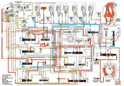
Fig. 16: Drive Range, Sixth Gear -- Gen 2/Hybrid Fluid Flow Diagram
Fluid passages (GEN 2/HYBRID)
Torque Converter and Differential Housing - Case Side
.gif)
Fig. 17: Torque Converter and Differential Housing -- Case Side
.jpg)
Fluid Pump Body - Fluid Pump Cover Side
.gif)
Fig. 18: Fluid Pump Body -- Fluid Pump Cover Side
.jpg)
Fluid Pump Cover - Fluid Pump Body Side
.gif)
Fig. 19: Fluid Pump Cover -- Fluid Pump Body Side
.jpg)
Case - Torque Converter and Differential Housing Side
.gif)
Fig. 20: Case -- Torque Converter and Differential Housing Side
.jpg)
Case - Control Valve Body Side
.gif)
Fig. 21: Case -- Control Valve Body Side Components Name
.jpg)
Control Valve Body Spacer Plate Assembly - Case Side
.gif)
Fig. 22: Control Valve Body Spacer Plate Assembly -- Case Side
Control Valve Body - Case Side
.gif)
Fig. 23: Control Valve Body -- Case Side
.jpg)
.jpg)
Control Valve Body - Channel Plate Side
.gif)
Fig. 24: Control Valve Body -- Channel Plate Side
.jpg)

Channel Plate to Valve Body Spacer Plate Assembly - Channel Plate Side
.gif)
Fig. 25: Channel Plate to Valve Body Spacer Plate Assembly -- Channel Plate
Side
.jpg)
Channel Plate - Control Valve Body Side
.gif)
Fig. 26: Channel Plate -- Control Valve Body Side
.jpg)
Channel Plate - Control Solenoid (w/Body and TCM) Valve Assembly Side
.gif)
Fig. 27: Channel Plate -- Control Solenoid (w/Body and TCM) Valve Assembly
Side

Control Solenoid (w/Body and TCM) Valve Assembly - Channel Plate Side

Fig. 28: Control Solenoid (w/Body and TCM) Valve Assembly -- Channel Plate
Side
.jpg)
READ NEXT:
 Specifications
FASTENER TIGHTENING SPECIFICATIONS (ON VEHICLE)
Fastener Tightening Specifications (On Vehicle)
FASTENER TIGHTENING SPECIFICATIONS (OFF VEHICLE)
Fastener Tightening Specifications (Off Vehicle)
Manual Transmission - M20 M32 (MR5)
SPECIFICATIONS
FASTENER TIGHTENING SPECIFICATIONS
Fastener Tightening Specifications
MANUAL TRANSMISSION SPECIFICATIONS
Manual Transmission Specifications
Schematic wiring diagrams
MANUAL TRANSM
Component locator
MANUAL TRANSMISSION COMPONENT VIEWS
Shift Control and Shift Lever/Selector Lever Cable Components
Fig. 3: Shift Control and Shift Lever/Selector Lever Cable Components
Shift Shaft Components
Fig
SEE MORE:
Towing the Vehicle
Caution
Incorrectly towing a disabled
vehicle may cause damage. The
damage would not be covered by
the vehicle warranty. Do not lash
or hook to suspension
components. Use the proper
straps around the tires to secure
the vehicle. Do not drag a locked
wheel/tire. Use tire skates or
dollies under any l
Secondary and Configurable Customer Controls - Diagnostic information and
procedures
DTC B1405: Control module voltage reference output 2
DIAGNOSTIC CODE INDEX
DTC B1405: CONTROL MODULE VOLTAGE REFERENCE OUTPUT 2
Diagnostic Instructions
Perform the Diagnostic System Check - Vehicle prior to using this
diagnostic procedure.
Review Strategy Based Diagnosis for an overview of th
