Buick Encore: Diagnostic information and procedures
DTC B0012 OR B0013: Driver steering wheel air bag deployment loop
DIAGNOSTIC CODE INDEX


DTC B0012 OR B0013: DRIVER STEERING WHEEL AIR BAG DEPLOYMENT LOOP
Diagnostic Instructions
- Perform the Diagnostic System Check - Vehicle prior to using this diagnostic procedure.
- Review Strategy Based Diagnosis for an overview of the diagnostic approach.
- Diagnostic Procedure Instructions provides an overview of each diagnostic category
DTC Descriptors
DTC B0012 01
Driver Steering Wheel Air Bag Deployment Loop Stage 1 Short to Battery
DTC B0012 02
Driver Steering Wheel Air Bag Deployment Loop Stage 1 Short to Ground
DTC B0012 04
Driver Steering Wheel Air Bag Deployment Loop Stage 1 Open
DTC B0012 0D
Driver Steering Wheel Air Bag Deployment Loop Stage 1 High Resistance
DTC B0012 0E
Driver Steering Wheel Air Bag Deployment Loop Stage 1 Low Resistance
DTC B0013 01
Driver Steering Wheel Air Bag Deployment Loop Stage 2 Short to Battery
DTC B0013 02
Driver Steering Wheel Air Bag Deployment Loop Stage 2 Short to Ground
DTC B0013 04
Driver Steering Wheel Air Bag Deployment Loop Stage 2 Open
DTC B0013 0D
Driver Steering Wheel Air Bag Deployment Loop Stage 2 High Resistance
DTC B0013 0E
Driver Steering Wheel Air Bag Deployment Loop Stage 2 Low Resistance
Diagnostic Fault Information

Circuit/System Description
During a frontal crash of sufficient force the inflatable restraint sensing and diagnostic module (SDM) will allow current to flow through the deployment loop in order to deploy the steering wheel air bag. The SDM performs continuous diagnostic tests on the deployment loops to check for proper circuit continuity and for shorts to ground or voltage. There are 2 shorting bars used within the steering wheel air bag coil connector which will short together both steering wheel air bag stage 1 high control circuit and steering wheel air bag stage 1 low control circuit and both steering wheel air bag stage 2 high control circuit and steering wheel air bag stage 2 low control circuit when the connector is disconnected. This will help to prevent unwanted deployment of the steering wheel air bag during servicing.
Conditions for Running the DTC
Ignition voltage is between 9-16 V.
Conditions for Setting the DTC
B0012 01 stage 1 or B0013 01 stage 2
The steering wheel air bag deployment loop is shorted to voltage for 2 seconds.
B0012 02 stage 1 or B0013 02 stage 2
The steering wheel air bag deployment loop is shorted to ground for 2 seconds.
B0012 04 stage 1 or B0013 04 stage 2
The steering wheel air bag deployment loop is open for 2 seconds.
B0012 0D stage 1 or B0013 0D stage 2
The steering wheel air bag deployment loop resistance is greater than 4.4 ohms for 2 seconds
B0012 0E stage 1 or B0013 0E stage 2
The steering wheel air bag deployment loop resistance is less than 1.7 ohms for 2 seconds.
Action Taken When the DTC Sets
- The inflatable restraint sensing and diagnostic module requests the instrument cluster to illuminate the AIR BAG indicator.
- The inflatable restraint sensing and diagnostic module will store a DTC, however if an event occurs the system will still attempt deployment.
Conditions for Clearing the DTC
- The condition for setting the DTC is no longer exists.
- A history DTC will clear once 100 malfunction-free ignition cycles have occurred.
Diagnostic Aid
NOTE: The following diagnostic aids apply for both current and history DTCs.
A worn steering wheel air bag coil can cause a repeated history DTC to set. To verify this condition, turn the steering wheel 360 degrees in one direction then back 360 degrees in the other direction, multiple times, while viewing the scan tool Deployment Loop Resistance parameters.
An incorrectly installed connector position assurance (CPA) or incorrectly seated connector can cause a shorting bar to short both control circuits together. Check the connectors and CPAs if a DTC with symptom byte 02 or 0E is set, to ensure the shorting bars are not causing the circuits to be shorted together. Shorting bars are used in the locations listed below:
- Steering wheel air bag assembly
- Steering wheel air bag coil assembly
- Inline harness connectors
- Harness side of the inflatable restraint sensing and diagnostic module connector
Terminal fretting or incorrectly seated connector can cause an open/high resistance condition. Check the circuit terminals for fretting or incorrectly seated connector if a DTC with symptom byte 04 or 0D is set.
Reference Information
Schematic Reference
SIR Schematics (Encore), SIR Schematics (Encore)
Connector End View Reference
WIRING SYSTEMS AND POWER MANAGEMENT - COMPONENT CONNECTOR END VIEWS - INDEX - ENCORE WIRING SYSTEMS AND POWER MANAGEMENT - COMPONENT CONNECTOR END VIEWS - INDEX - Encore
Description and Operation
Supplemental Inflatable Restraint System Description and Operation
Electrical Information Reference
- Circuit Testing
- Testing for Intermittent Conditions and Poor Connections
- Wiring Repairs
- Connector Repairs
Scan Tool Reference
Control Module References for scan tool information
Special Tools
EL-38125-580 Terminal Release Tool Kit
Circuit/System Verification
NOTE:
- Refer to SIR Service Precautions.
- Inspect all terminals for damage or corrosion when disconnecting connectors. Damage or corrosion in the following requires repair or replacement of the affected component/connector
- Driver steering wheel air bag
- Driver steering wheel air bag coil
- Inflatable restraint sensing and diagnostic module
- Air bag wiring harness connector
- Inflatable restraint sensing and diagnostic module wiring harness connector
- The connector and connector position assurance (CPA) may seat independent of each other. Both the connector and CPA should seat with an audible and/or tactile click. The CPA isolates the shorting-bars within the connector allowing the deployment circuit to operate properly. Replace any CPA that is damaged or missing.
- If the condition is intermittent or cannot be duplicated, disconnect the connectors and add dielectric grease / lubricant (Nyogel 760G or equivalent, meeting GM specification 9986087). This procedure will correct the high resistance condition due to terminal fretting corrosion.
- Verify the appropriate scan tool Deployment Loop Resistance parameters stay consistently between 2.1- 4.0 ohms without any spikes or dropouts while turning the steering wheel 360 degrees in one direction then back 360 degrees in the other direction.
- If less than 2.1 ohms or greater than 4.0 ohms
Refer to Circuit/System Testing.
- If there are spikes or dropouts
Replace the X85 Steering Wheel Air Bag Coil.
- If between 2.1-4.0 ohms without any spikes or dropouts
- Verify DTC B0012 or B0013 is only set as a history DTC.
- If the DTC is set as current
Refer to Circuit/System Testing.
- If the DTC is set as history
- Verify the scan tool Deployment Loop Resistance parameters stay consistently between 2.1-4.0 ohms without any drop outs or spikes while moving the harness near each connector listed below.
- X85 Steering Wheel Air Bag Coil
- F107 Steering Wheel Air Bag
- Any inline harness connector
- K36 Inflatable Restraint Sensing and Diagnostic Module
- If the reading is erratic while moving the harness, perform the following
- Inspect each connector terminal for damage or corrosion and repair as necessary
- Apply dielectric grease / lubricant (Nyogel 760G or equivalent, meeting GM specification 9986087) to each connector terminal
- Ensure each connector and CPA is correctly seated
- If between 2.1-4.0 ohms without any spikes or dropouts
- All OK.
Circuit/System Testing
- Ignition OFF, disconnect the scan tool and disconnect the appropriate harness connector listed below at the F107 Driver Steering Wheel Air Bag.
- DTC B0012 connector X1
- DTC B0013 connector X2
- Test for greater than 25 ohms between the control circuit terminal 1 and the control circuit terminal 2.
- If 25 ohms or less
- Disconnect the X1 harness connector at the K36 Inflatable Restraint Sensing and Diagnostic Module.
NOTE: Some connectors may be equipped with shorting bars as a safety component to prevent accidental deployment. When testing on a connector with shorting bars, the shorting bars must be disabled to ensure accurate test results. Insert an appropriate pick from EL- 38125-580 and depress the shorting bars above the appropriate terminals. This will lift the shorting bar from the terminal and allow accurate test results. Take care not to damage the connector, shorting bar, or terminal when depressing the shorting bar.
- Test for infinite resistance between the two control circuits.
- If less than infinite resistance, repair the short between the two circuits.
- If infinite resistance, replace the K36 Inflatable Restraint Sensing and Diagnostic Module.
- If greater than 25 ohms
- Ignition ON.
- Test for less than 11 V between each control circuit terminal listed below and ground:
- Control circuit terminal 1
- Control circuit terminal 2
- If 11 V or greater
- Ignition OFF, disconnect the X1 harness connector at the K36 Inflatable Restraint Sensing and Diagnostic Module, ignition ON.
- Test for less than 1 V between the control circuit and ground.
- If 1 V or greater, repair the short to voltage on the circuit.
- If less than 1 V, replace the K36 Inflatable Restraint Sensing and Diagnostic Module.
- If less than 11 V
- Ignition OFF.
- Test for greater than 25 ohms between each control circuit terminal listed below and ground:
- Control circuit terminal 1
- Control circuit terminal 2
- If 25 ohms or less
- Disconnect the X1 harness connector at the K36 Inflatable Restraint Sensing and Diagnostic Module.
NOTE:
Some connectors may be equipped with shorting bars as a safety component to prevent accidental deployment. When testing on a connector with shorting bars, the shorting bars must be disabled to ensure accurate test results. Insert an appropriate pick from EL- 38125-580 and depress the shorting bars above the appropriate terminals. This will lift the shorting bar from the terminal and allow accurate test results. Take care not to damage the connector, shorting bar, or terminal when depressing the shorting bar.
- Test for infinite resistance between the control circuit and ground.
- If less than infinite resistance, repair the short to ground on the circuit.
- If infinite resistance, replace the K36 Inflatable Restraint Sensing and Diagnostic Module.
- If greater than 25 ohms
- Install a 3 A fused jumper wire between the control circuit terminal 1 and the control circuit terminal 2, ignition ON.
- Verify DTC B0012 0E or B0013 0E is set while turning the steering wheel 360 degrees in one direction then back 360 degrees in the other direction.
If DTC B0012 0E or B0013 0E is not set
- Ignition OFF, disconnect the X1 harness connector at the K36 Inflatable Restraint Sensing and Diagnostic Module.
- Test for less than 2 ohms in the K85 Steering Wheel Airbag Coil and each control circuit end to end.
- If 2 ohms or greater, replace the X85 Steering Wheel Air Bag Coil or repair the open/high resistance in the circuit.
- If less than 2 ohms, replace the K36 Inflatable Restraint Sensing and Diagnostic Module.
- If DTC B0012 0E or B0013 0E is set
- Ignition OFF, connect the harness connector at the F107 Steering Wheel Air Bag, press in the CPA (if equipped) until an audible and/or tactile click is heard.
- Ignition ON, clear DTCs. Operate the vehicle within the Conditions for Running the DTC.
- Verify DTC B0012 or B0013 is not set.
- If DTC B0012 or B0013 is set
Test or replace the F107 Steering Wheel Air Bag.
- If DTC B0012 or B0013 is not set
- All OK.
Repair Instructions
Perform the Diagnostic Repair Verification after completing the repair.
- Steering Wheel Airbag Coil Replacement (Encore), Steering Wheel Airbag Coil Replacement (Encore)
- Steering Wheel Airbag Replacement (Encore), Steering Wheel Airbag Replacement (Encore) SIR/SRS Wiring Repairs
- Control Module References for inflatable restraint sensing and diagnostic module replacement, programming and setup
DTC B0014, B0021, B0031, OR B0038: Seat side air bag deployment loop
Diagnostic Instructions
- Perform the Diagnostic System Check - Vehicle prior to using this diagnostic procedure.
- Review Strategy Based Diagnosis for an overview of the diagnostic approach.
- Diagnostic Procedure Instructions provides an overview of each diagnostic category.
DTC Descriptors
DTC B0014 01
Driver Seat Side Air Bag Deployment Loop Short to Battery
DTC B0014 02
Driver Seat Side Air Bag Deployment Loop Short to Ground
DTC B0014 04
Driver Seat Side Air Bag Deployment Loop Open
DTC B0014 0D
Driver Seat Side Air Bag Deployment Loop High Resistance
DTC B0014 0E
Driver Seat Side Air Bag Deployment Loop Low Resistance
DTC B0021 01
Passenger Seat Side Air Bag Deployment Loop Short to Battery
DTC B0021 02
Passenger Seat Side Air Bag Deployment Loop Short to Ground
DTC B0021 04
Passenger Seat Side Air Bag Deployment Loop Open
DTC B0021 0D
Passenger Seat Side Air Bag Deployment Loop High Resistance
DTC B0021 0E
Passenger Seat Side Air Bag Deployment Loop Low Resistance
DTC B0031 01
Left Rear Seat Side Air Bag Deployment Loop Short to Battery
DTC B0031 02
Left Rear Seat Side Air Bag Deployment Loop Short to Ground
DTC B0031 04
Left Rear Seat Side Air Bag Deployment Loop Open
DTC B0031 0D
Left Rear Seat Side Air Bag Deployment Loop High Resistance
DTC B0031 0E
Left Rear Seat Side Air Bag Deployment Loop Low Resistance
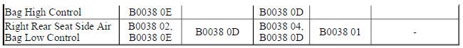
DTC B0038 01
Right Rear Seat Side Air Bag Deployment Loop Short to Battery
DTC B0038 02
Right Rear Seat Side Air Bag Deployment Loop Short to Ground
DTC B0038 04
Right Rear Seat Side Air Bag Deployment Loop Open
DTC B0038 0D
Right Rear Seat Side Air Bag Deployment Loop High Resistance
DTC B0038 0E
Right Rear Seat Side Air Bag Deployment Loop Low Resistance
Diagnostic Fault Information

Circuit/System Description
During a side or frontal crash of sufficient force, the inflatable restraint sensing and diagnostic module (SDM) will allow current to flow through the deployment loop in order to deploy an air bag. There are 2 shorting bars used within the connector that will short the control circuits together when the connector is disconnected. This will help to prevent unwanted deployment of the air bag or retractor pretensioner during servicing.
Conditions for Running the DTC
Ignition voltage is between 9-16 V.
Conditions for Setting the DTC
B0014 01, B0021 01, B0031 01, B0038 01
The air bag control circuit is shorted to voltage for 2 seconds.
B0014 02, B0021 02, B0031 02, B0038 02
The air bag control circuit is shorted to ground for 2 seconds.
B0014 04, B0021 04, B0031 04, B0038 04
The air bag control circuit is open for 2 seconds.
B0014 0D, B0021 0D, B0031 0D, B0038 0D
The air bag deployment loop resistance is greater than 4.2 ohms for 2 seconds.
B0014 0E, B0021 0E, B0031 0E, B0038 0E
The air bag deployment loop resistance is less than 1.4 ohms for 2 seconds.
Action Taken When the DTC Sets
- The inflatable restraint sensing and diagnostic module requests the instrument cluster to illuminate the AIR BAG indicator.
- The inflatable restraint sensing and diagnostic module will store a DTC, however if an event occurs the system will still attempt deployments.
Conditions for Clearing the DTC
- The condition for setting the DTC no longer exists.
- A history DTC will clear once 100 malfunction-free ignition cycles have occurred.
Diagnostic Aid
NOTE: The following diagnostic aids apply for both current and history DTCs.
An incorrectly installed connector position assurance (CPA) or incorrectly seated connector can cause a shorting bar to short both control circuits together. Check the connectors and CPAs if a DTC with symptom byte 02 or 0E is set, to ensure the shorting bars are not causing the circuits to be shorted together. Shorting bars are used in the locations listed below:
- Front and rear seat side air bags
- Left and right roof rail air bags
- Inline harness connectors
- Harness side of the inflatable restraint sensing and diagnostic module connector
Terminal fretting or incorrectly seated connector can cause an open/high resistance condition. Check the circuit terminals for fretting or incorrectly seated connector if a DTC with symptom byte 04 or 0D is set. DTCs of deployment loops which are in the seat can occur because of stress or damage to the harness due to seat movement. Move the seat to the full extent of travel while using the scan tool to observe deployment type loop parameters.
Reference Information
Schematic Reference
SIR Schematics (Encore), SIR Schematics (Encore)
Connector End View Reference
WIRING SYSTEMS AND POWER MANAGEMENT - COMPONENT CONNECTOR END VIEWS - INDEX - ENCORE WIRING SYSTEMS AND POWER MANAGEMENT - COMPONENT CONNECTOR END VIEWS - INDEX - Encore
Description and Operation
Supplemental Inflatable Restraint System Description and Operation
Electrical Information Reference
- Circuit Testing
- Testing for Intermittent Conditions and Poor Connections
- Wiring Repairs
- Connector Repairs
Scan Tool Reference
Control Module References for scan tool information
Special Tools
EL-38125-580 Terminal Release Tool Kit
Circuit/System Verification
NOTE:
- Refer to SIR Service Precautions.
- Inspect all terminals for damage or corrosion when disconnecting connectors. Damage or corrosion in the following requires repair or replacement of the affected component/connector.
- Seat side air bag
- Inflatable restraint sensing and diagnostic module
- All wiring harness connectors
- Inflatable restraint sensing and diagnostic module wiring harness connecto
- The connector and connector position assurance (CPA) may seat independent of each other. Both the connector and CPA should seat with an audible and/or tactile click. The CPA isolates the shorting-bars within the connector allowing the deployment circuit to operate properly.
- If the condition is intermittent or cannot be duplicated, disconnect the connectors and add dielectric grease/lubricant (Nyogel 760G or equivalent, meeting GM specification 9986087). This procedure will correct the high resistance condition due to terminal fretting corrosion.
- Verify the appropriate scan tool Deployment Loop Resistance parameters stay consistently between 2.1- 4.0 ohms without any spikes or dropouts while moving the harness near each connector.
- F106 Seat Side Air Bag
- Any inline harness connector
- K36 Inflatable Restraint Sensing and Diagnostic Module
- If less than 2.1 ohms or greater than 4.0 ohms
Refer to Circuit/System Testing.
If there are spikes or dropouts, perform the following:
- Inspect each connector terminal and harness for damage or corrosion and repair as necessary.
- Apply dielectric grease/lubricant (Nyogel 760G or equivalent, meeting GM specification 9986087) to each connector terminal.
- Ensure each connector and CPA is correctly seated.
- If between 2.1-4.0 ohms without any spikes or dropouts
- All OK
Circuit/System Testing
- Ignition OFF, scan tool disconnected, disconnect the harness connector at the appropriate F106 Seat Side Air Bag.
- Test for greater than 25 ohms between the control circuit terminals 1 and 2.
If 25 ohms or less
- Disconnect the X2 harness connector at the K36 Inflatable Restraint Sensing and Diagnostic Module.
NOTE: Some connectors may be equipped with shorting bars as a safety component to prevent accidental deployment. When testing on a connector with shorting bars, the shorting bars must be disabled to ensure accurate test results. Insert an appropriate pick from EL- 38125-580 and depress the shorting bars above the appropriate terminals. This will lift the shorting bar from the terminal and allow accurate test results. Take care not to damage the connector, shorting bar, or terminal when depressing the shorting bar.
- Test for infinite resistance between the 2 control circuits.
- If less than infinite resistance, repair the short between the 2 circuits.
- If infinite resistance, replace the K36 Inflatable Restraint Sensing and Diagnostic Module.
- If greater than 25 ohms
- Ignition ON.
- Test for less than 11 V between each control circuit terminal listed below and ground:
- Control circuit terminal 1
- Control circuit terminal 2
- If 11 V or greater
- Ignition OFF, disconnect the X2 harness connector at the K36 Inflatable Restraint Sensing and Diagnostic Module, ignition ON.
- Test for less than 1 V between the control circuit and ground.
- If 1 V or greater, repair the short to voltage on the circuit.
- If less than 1 V, replace the K36 Inflatable Restraint Sensing and Diagnostic Module.
- If less than 11 V
- Ignition OFF.
- Test for greater than 25 ohms between each control circuit terminal listed below and ground:
- Control circuit terminal 1
- Control circuit terminal 2
- If 25 ohms or less
- Disconnect the X2 harness connector at the K36 Inflatable Restraint Sensing and Diagnostic Module.
- Test for infinite resistance between the control circuit and ground.
- If less than infinite resistance, repair the short to ground on the circuit.
- If infinite resistance, replace the K36 Inflatable Restraint Sensing and Diagnostic Module.
- If greater than 25 ohms
- Install a 3 A fused jumper wire between the control circuit terminals 1 and 2, ignition ON.
- Verify DTC B0014 0E, B0021 0E, B0031 0E, or B0038 0E is set.
- If B0014 0E, B0021 0E, B0031 0E, or B0038 0E is not set
- Ignition OFF, disconnect the X2 harness connector at the K36 Inflatable Restraint Sensing and Diagnostic Module.
- Test for less than 2 ohms in each control circuit end to end.
- If 2 ohms or greater, repair the open/high resistance in the circuit.
- If less than 2 ohms, replace the K36 Inflatable Restraint Sensing and Diagnostic Module.
- If B0014 0E, B0021 0E, B0031 0E, or B0038 0E is set
- Ignition OFF, connect the harness connector at the F106 Seat Side Air Bag, press in the CPA (if equipped) until an audible and/or tactile click is heard.
- Ignition ON, clear DTCs. Operate the vehicle within the Conditions for Running the DTC.
- Verify DTC B0014, B0021, B0031, or B0038 is not set.
- If DTC B0014, B0021, B0031, or B0038 is set
Test or replace the F106 Seat Side Air Bag.
- If DTC B0014, B0021, B0031, or B0038 is not set
- All OK.
Repair Instructions
Perform the Diagnostic Repair Verification after completing the repair.
- Front Seat Outboard Seat Back Airbag Replacement
- Rear Seat Bolster Airbag Replacement (AYF)
- Control Module References for inflatable restraint sensing and diagnostic module replacement, programming, and setup
DTC B0015, B001A, B001B, OR B0022: Seat belt retractor pretensioner deployment loop
Diagnostic Instructions
- Perform the Diagnostic System Check - Vehicle prior to using this diagnostic procedure.
- Review Strategy Based Diagnosis for an overview of the diagnostic approach.
- Diagnostic Procedure Instructions provides an overview of each diagnostic category.
DTC Descriptors
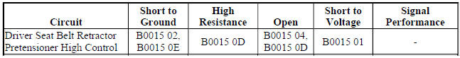
DTC B0015 01
Driver Seat Belt Retractor Pretensioner Deployment Loop Short to Battery
DTC B0015 02
Driver Seat Belt Retractor Pretensioner Deployment Loop Short to Ground
DTC B0015 04
Driver Seat Belt Retractor Pretensioner Deployment Loop Open
DTC B0015 0D
Driver Seat Belt Retractor Pretensioner Deployment Loop High Resistance
DTC B0015 0E
Driver Seat Belt Retractor Pretensioner Deployment Loop Low Resistance
DTC B001A 01
Driver Seat Belt Anchor Pretensioner Deployment Loop Short to Battery
DTC B001A 02
Driver Seat Belt Anchor Pretensioner Deployment Loop Short to Ground
DTC B001A 04
Driver Seat Belt Anchor Pretensioner Deployment Loop Open
DTC B001A 0D
Driver Seat Belt Anchor Pretensioner Deployment Loop High Resistance
DTC B001A 0E
Driver Seat Belt Anchor Pretensioner Deployment Loop Low Resistance
DTC B001B 01
Passenger Seat Belt Anchor Pretensioner Deployment Loop Short to Battery
DTC B001B 02
Passenger Seat Belt Anchor Pretensioner Deployment Loop Short to Ground
DTC B001B 04
Passenger Seat Belt Anchor Pretensioner Deployment Loop Open
DTC B001B 0D
Passenger Seat Belt Anchor Pretensioner Deployment Loop High Resistance
DTC B001B 0E
Passenger Seat Belt Anchor Pretensioner Deployment Loop Low Resistance
DTC B0022 01
Passenger Seat Belt Retractor Pretensioner Deployment Loop Short to Battery
DTC B0022 02
Passenger Seat Belt Retractor Pretensioner Deployment Loop Short to Ground
DTC B0022 04
Passenger Seat Belt Retractor Pretensioner Deployment Loop Open Circuit
DTC B0022 0D
Passenger Seat Belt Retractor Pretensioner Deployment Loop High Resistance
DTC B0022 0E
Passenger Seat Belt Retractor Pretensioner Deployment Loop Low Resistance
Diagnostic Fault Information

Circuit/System Description
During a side or frontal crash of sufficient force the inflatable restraint sensing and diagnostic module (SDM) will allow current to flow through the deployment loop in order to deploy an air bag or pretensioner. There are 2 shorting bars which will short the control circuits together when the connector is disconnected. This will help to prevent unwanted deployment of the air bag or pretensioner during servicing.
Conditions for Running the DTC
Ignition voltage is between 9-16 V.
Conditions for Setting the DTC
B0015 01, B001A 01, B001B 01, B0022 01
The pretensioner control circuit is shorted to voltage for 2 seconds.
B0015 02, B001A 02, B001B 02, B0022 02
The pretensioner control circuit is shorted to ground for 2 seconds.
B0015 04, B001A 04, B001B 04, B0022 04
The pretensioner control circuit is open for 2 seconds.
B0015 0D, B001A 0D, B001B 0D, B0022 0D
The pretensioner deployment loop resistance is greater than 4.2 ohms for 2 seconds.
B0015 0E, B001A 0E, B001B 0E, B0022 0E
The pretensioner deployment loop resistance is less than 1.4 ohms for 2 seconds.
Action Taken When the DTC Sets
- The Inflatable Restraint and Sensing Diagnostic Module requests the instrument cluster to illuminate the AIR BAG indicator.
- The Inflatable Restraint and Sensing Diagnostic Module will store a DTC, however if an event occurs the system will still attempt deployments.
Conditions for Clearing the DTC
- The condition for setting the DTC no longer exists.
- A history DTC will clear once 100 malfunction-free ignition cycles have occurred.
Diagnostic Aid
NOTE: The following diagnostic aids apply for both current and history DTCs.
An incorrectly installed connector position assurance (CPA) or incorrectly seated connector can cause a shorting bar to short both control circuits together. Check the connectors and CPAs if a DTC with symptom byte 02 or 0E is set, to ensure the shorting bars are not causing the circuits to be shorted together. Shorting bars are used in the locations listed below:
- Driver and passenger anchor or retractor pretensioners
- Inline harness connectors
- Harness side of the Inflatable Restraint and Sensing Diagnostic Module connector
Terminal fretting or incorrectly seated connectors can cause an open/high resistance condition. Check the circuit terminals for fretting or incorrectly seated connector if a DTC with symptom byte 04 or 0D is set. DTCs of deployment loops which are in the seat can occur because of stress or damage to the harness due to seat movement. Move the seat to the full extent of travel while using the scan tool to observe deployment type loop parameters.
Reference Information
Schematic Reference
SIR Schematics (Encore), SIR Schematics (Encore)
Connector End View Reference
WIRING SYSTEMS AND POWER MANAGEMENT - COMPONENT CONNECTOR END VIEWS - INDEX - ENCORE WIRING SYSTEMS AND POWER MANAGEMENT - COMPONENT CONNECTOR END VIEWS - INDEX - Encore
Description and Operation
Supplemental Inflatable Restraint System Description and Operation
Electrical Information Reference
- Circuit Testing
- Testing for Intermittent Conditions and Poor Connections
- Wiring Repairs
- Connector Repairs
Scan Tool Reference
Control Module References for scan tool information
Special Tools
EL-38125-580 Terminal Release Tool Kit
Circuit/System Verification
NOTE:
- Refer to SIR Service Precautions.
- Inspect all terminals for damage or corrosion when disconnecting connectors. Damage or corrosion in the following requires repair or replacement of the affected component/connector.
- Seat belt retractor pretensioner
- Inflatable restraint and sensing diagnostic module
- Seat belt retractor pretensioner wiring harness connector
- Passenger instrument panel air bag wiring harness connector
- Seat side air bag wiring harness connector
- Roof rail air bag wiring harness connector
- Inflatable Restraint and Sensing Diagnostic Module wiring harness connector
- The connector and connector position assurance (CPA) may seat independent of each other. Both the connector and CPA should seat with an audible and/or tactile click. The CPA isolates the shorting-bars within the connector allowing the deployment circuit to operate properly.
- If the condition is intermittent or cannot be duplicated, disconnect the connectors and add dielectric grease / lubricant (Nyogel 760G or equivalent, meeting GM specification 9986087). This procedure will correct the high resistance condition due to terminal fretting corrosion.
- Verify the appropriate scan tool Deployment Loop Resistance parameters stay consistently between 2.1-4.0 ohms without any spikes or dropouts while moving the harness near each connector listed below:
- F112 Seat Belt Retractor Pretensioner
- F113 Seat Belt Anchor Pretensioner
- Any inline harness connector
- K36 Inflatable Restraint and Sensing Diagnostic Module
- If less than 2.1 ohms or greater than 4.0 ohms
Refer to Circuit/System Testing.
- If there are spikes or dropouts, perform the following
- Inspect each connector terminal and harness for damage or corrosion and repair as necessary
- Ensure each connector and CPA is correctly seated.
- If between 2.1-4.0 ohms without any spikes or dropouts
- All OK
Circuit/System Testing
- Ignition OFF, scan tool disconnected, disconnect the appropriate harness connector listed below. It may take up to 2 min for all vehicle systems to power down.
- F112 Seat Belt Retractor Pretensioner
- F113 Seat Belt Anchor Pretensioner
- Test for greater than 25 ohms between the control circuit terminals 1 and 2.
- If 25 ohms or less
- Disconnect the X2 harness connector at the K36 Inflatable Restraint and Sensing Diagnostic Module.
NOTE:
Some connectors may be equipped with shorting bars as a safety component to prevent accidental inflator deployment. When testing on a connector with shorting bars, the shorting bars must be disabled to ensure accurate test results. Insert an appropriate pick from EL-38125-580 and depress the shorting bars above the appropriate terminals. This will lift the shorting bar from the terminal and allow accurate test results. Take care not to damage the connector, shorting bar, or terminal when depressing the shorting bar.
- Test for infinite resistance between the two control circuits.
- If less than infinite resistance, repair the short between the two circuits.
- If infinite resistance, replace the K36 Inflatable Restraint and Sensing Diagnostic Module.
- If greater than 25 ohms
- Ignition ON.
- Test for less than 11 V between each control circuit terminal listed below and ground:
- Control circuit terminal 1
- Control circuit terminal 2
- If 11 V or greater
- Ignition OFF, disconnect the X2 harness connector at the K36 Inflatable Restraint and Sensing Diagnostic Module, ignition ON
- Test for less than 1 V between the control circuit and ground.
- If 1 V or greater, repair the short to voltage on the circuit.
- If less than 1 V, replace the K36 Inflatable Restraint and Sensing Diagnostic Module.
- If less than 11 V
- Ignition OFF.
- Test for greater than 25 ohms between each control circuit terminal listed below and ground:
- Control circuit terminal 1
- Control circuit terminal 2
- If 25 ohms or less
- Disconnect the X2 harness connector at the K36 Inflatable Restraint and Sensing Diagnostic Module.
- Test for infinite resistance between the control circuit and ground.
- If less than infinite resistance, repair the short to ground on the circuit.
- If infinite resistance, replace the K36 Inflatable Restraint and Sensing Diagnostic Module.
- If greater than 25 ohms
- Install a 3 A fused jumper wire between the control circuit terminals 1 and 2, ignition ON.
- Verify DTC B0015 0E, B001A 0E, B001B 0E, or B0022 0E is set.
If B0015 0E, B001A 0E, B001B 0E, or B0022 0E is not set
- Ignition OFF, disconnect the X2 harness connector at the K36 Inflatable Restraint and Sensing Diagnostic Module.
- Test for less than 2 ohms in each control circuit end to end.
- If 2 ohms or greater, repair the open/high resistance in the circuit.
- If less than 2 ohms, replace the K36 Inflatable Restraint and Sensing Diagnostic Module.
- If B0015 0E, B001A 0E, B001B 0E, or B0022 0E is set
- Ignition OFF, connect the harness connector at the F112 Seat Belt Retractor Pretensioner or F113 Seat Belt Anchor Pretensioner, press in the CPA (if equipped) until an audible and/or tactile click is heard.
- Ignition ON, clear DTCs. Operate the vehicle within the Conditions for Running the DTC.
- Verify DTC B0015, B001A, B001B, or B0022 is not set.
- If DTC B0015, B001A, B001B, or B0022 is set
Replace the F112 Seat Belt Retractor Pretensioner or F113 Seat Belt Anchor Pretensioner.
- If DTC B0015, B001A, B001B, or B0022 is not set
- All OK.
Repair Instructions
Perform the Diagnostic Repair Verification after completing the repair.
- Front Seat Belt Anchor Plate Tensioner Replacement
- Front Seat Belt Retractor Replacement (With A69)
- SIR/SRS Wiring Repairs
- Control Module References for Inflatable Restraint and Sensing Diagnostic Module replacement, programming and setup
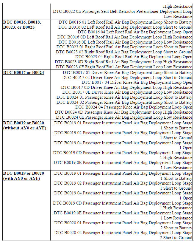
DTC B0016, B0018, B0023, OR B0025: Roof rail air bag deployment loop
Diagnostic Instructions
- Perform the Diagnostic System Check - Vehicle prior to using this diagnostic procedure.
- Review Strategy Based Diagnosis for an overview of the diagnostic approach.
- Diagnostic Procedure Instructions provides an overview of each diagnostic category.
DTC Descriptors
DTC B0016 01
Left Roof Rail Air Bag Deployment Loop Short to Battery
DTC B0016 02
Left Roof Rail Air Bag Deployment Loop Short to Ground
DTC B0016 04
Left Roof Rail Air Bag Deployment Loop Open
DTC B0016 0D
Left Roof Rail Air Bag Deployment Loop High Resistance
DTC B0016 0E
Left Roof Rail Air Bag Deployment Loop Low Resistance
DTC B0023 01
Right Roof Rail Air Bag Deployment Loop Short to Battery
DTC B0023 02
Right Roof Rail Air Bag Deployment Loop Short to Ground
DTC B0023 04
Right Roof Rail Air Bag Deployment Loop Open
DTC B0023 0D
Right Roof Rail Air Bag Deployment Loop High Resistance
DTC B0023 0E
Right Roof Rail Air Bag Deployment Loop Low Resistance
Diagnostic Fault Information

Circuit/System Description
During a side or frontal crash of sufficient force the inflatable restraint sensing and diagnostic module (SDM) will allow current to flow through the deployment loop in order to deploy an air bag or pretensioner. There are 2 shorting bars which will short together control circuits, when the connector is disconnected. This will help to prevent unwanted deployment of the air bag or pretensioner during servicing.
Conditions for Running the DTC
Ignition voltage is between 9-16 V.
Conditions for Setting the DTC
B0016 01, B0023 01
The air bag control circuit is shorted to voltage for 2 seconds.
B0016 02, B0023 02
The air bag control circuit is shorted to ground for 2 seconds.
B0016 04, B0023 04
The air bag control circuit is open for 2 seconds.
B0016 0D, B0023 0D
The air bag deployment loop resistance is greater than 4.2 ohms for 2 seconds.
B0016 0E, B0023 0E
The air bag deployment loop resistance is less than 1.4 ohms for 2 seconds
Action Taken When the DTC Sets
- The inflatable restraint sensing and diagnostic module requests the instrument cluster to illuminate the AIR BAG indicator.
- The inflatable restraint sensing and diagnostic module will store a DTC, however if an event occurs the system will still attempt deployments.
Conditions for Clearing the DTC
- The condition for setting the DTC no longer exists.
- A history DTC will clear once 100 malfunction-free ignition cycles have occurred.
Diagnostic Aid
NOTE: The following diagnostic aids apply for both current and history DTCs.
An incorrectly installed connector position assurance (CPA) or incorrectly seated connector can cause a shorting bar to short both control circuits together. Check the connectors and CPAs if a DTC with symptom byte 02 or 0E is set, to ensure the shorting bars are not causing the circuits to be shorted together. Shorting bars are used in the locations listed below:
- Left and right roof rail air bags
- Inline harness connectors
- Harness side of the inflatable restraint sensing and diagnostic module connector
Terminal fretting or incorrectly seated connectors can cause an open/high resistance condition. Check the circuit terminals for fretting or incorrectly seated connector if a DTC with symptom byte 04 or 0D is set. DTCs of deployment loops which are in the seat DTC can occur because of stress or damage to the harness due to seat movement. Move the seat to the full extent of travel while using the scan tool to observe deployment type loop parameters.
Reference Information
Schematic Reference
SIR Schematics (Encore), SIR Schematics (Encore)
Connector End View Reference
WIRING SYSTEMS AND POWER MANAGEMENT - COMPONENT CONNECTOR END VIEWS - INDEX - ENCORE WIRING SYSTEMS AND POWER MANAGEMENT - COMPONENT CONNECTOR END VIEWS - INDEX - Encore
Description and Operation
Supplemental Inflatable Restraint System Description and Operation
Electrical Information Reference
- Circuit Testing
- Testing for Intermittent Conditions and Poor Connections
- Wiring Repairs
- Connector Repairs
Scan Tool Reference
Control Module References for scan tool information
Special Tools
EL-38125-580 Terminal Release Tool Kit
Circuit/System Verification
NOTE:
- Refer to SIR Service Precautions.
- Inspect all terminals for damage or corrosion when disconnecting connectors. Damage or corrosion in the following requires repair or replacement of the affected component/connector.
- Roof rail air bag
- Roof rail air bag wiring harness connector
- Inflatable restraint sensing and diagnostic module
- Inflatable restraint sensing and diagnostic module wiring harness connector
- The connector and connector position assurance (CPA) may seat independent of each other. Both the connector and CPA should seat with an audible and/or tactile click. The CPA isolates the shorting-bars within the connector allowing the deployment circuit to operate properly.
- If the condition is intermittent or cannot be duplicated, disconnect the connectors and add dielectric grease / lubricant (Nyogel 760G or equivalent, meeting GM specification 9986087). This procedure will correct the high resistance condition due to terminal fretting corrosion
- Verify DTC B0016 or B0023 is only set as a history DTC
- If the DTC is set as current
Refer to Circuit/System Testing.
- If the DTC is set as history
- Verify DTC B0016 or B0023 is only set as a history DTC while moving the harness near each connector listed below:
- F105L Roof Rail Air Bag - Left
- F105R Roof Rail Air Bag - Right
- Any inline harness connector
- K36 inflatable restraint sensing and diagnostic module
- If the DTC is set as current while moving the harness, perform the following
- Inspect each connector terminal for damage or corrosion and repair as necessary Apply dielectric grease / lubricant (Nyogel 760G or equivalent, meeting GM specification 9986087) to each connector terminal
- Ensure each connector and CPA is correctly seated
- If the DTC is set as history
- All OK.
Circuit/System Testing
- Ignition OFF. Scan tool disconnected. Disconnect the harness connector at the appropriate F105 Roof Rail Air Bag. It may take up to 2 min for all vehicle systems to power down.
- Test for greater than 25 ohms between the control circuit terminals 1 and 2.
- If 25 ohms or less
- Disconnect the X2 harness connector at the K36 Inflatable Restraint Sensing and Diagnostic Module.
NOTE: Some connectors may be equipped with shorting bars as a safety component to prevent accidental inflator deployment. When testing on a connector with shorting bars, the shorting bars must be disabled to ensure accurate test results. Insert an appropriate pick from EL-38125-580 and depress the shorting bars above the appropriate terminals. This will lift the shorting bar from the terminal and allow accurate test results. Take care not to damage the connector, shorting bar, or terminal when depressing the shorting bar.
- Test for infinite resistance between the two control circuits.
- If less than infinite resistance, repair the short between the two circuits.
- If infinite resistance, replace the K36 Inflatable Restraint Sensing and Diagnostic Module.
- If greater than 25 ohms
- Ignition ON.
- Test for less than 11 V between the control circuit terminals listed below and ground:
- Control circuit terminal 1
- Control circuit terminal 2
- If 11 V or greater
- Ignition OFF. Disconnect the X2 harness connector at the K36 Inflatable Restraint Sensing and Diagnostic Module. Ignition ON.
- Test for less than 1 V between the control circuit and ground.
- If 1 V or greater, repair the short to voltage on the circuit.
- If less than 1 V, replace the K36 Inflatable Restraint Sensing and Diagnostic Module.
- If less than 11 V
- Ignition OFF.
- Test for greater than 25 ohms between the control circuit terminals listed below and ground:
- Control circuit terminal 1
- Control circuit terminal 2
- If 25 ohms or less
- Disconnect the X2 harness connector at the K36 Inflatable Restraint Sensing and Diagnostic Module.
- Test for infinite resistance between the control circuit and ground.
- If less than infinite resistance, repair the short to ground on the circuit.
- If infinite resistance, replace the K36 Inflatable Restraint Sensing and Diagnostic Module.
- If greater than 25 ohms
- Ignition OFF. Install a 3 A fused jumper wire between the control circuit terminals 1 and 2. Ignition ON.
- Verify DTC B0016 0E or B0023 0E is set
- If DTC B0016 0E or B0023 0E is not set
- Ignition OFF. Disconnect the X2 harness connector at the K36 Inflatable Restraint Sensing and Diagnostic Module.
- Test for less than 2 ohms in each control circuit end to end.
- If 2 ohms or greater, repair the open/high resistance in the circuit.
- If less than 2 ohms, replace the K36 inflatable restraint sensing and diagnostic module.
- If DTC B0016 0E or B0023 0E is set
- Ignition OFF, connect the harness connector at the F105 Roof Rail Air Bag, press in the CPA (if equipped) until an audible and/or tactile click is heard.
- Ignition ON, clear DTCs. Operate the vehicle within the Conditions for Running the DTC.
- Verify DTC B0016 or B0023 is not set.
- If DTC B0016 or B0023 is set
Test or replace the F105 Roof Rail Air Bag.
- If DTC B0016 or B0023 is not set
- All OK.
Repair Instructions
Perform the Diagnostic Repair Verification after completing the repair.
- Airbag Roof Side Rail Module Replacement (Encore), Airbag Roof Side Rail Module Replacement (Encore)
- SIR/SRS Wiring Repairs
- Control Module References for inflatable restraint sensing and diagnostic module replacement, programming and setup
DTC B0017 OR B0024: Knee air bag deployment loop
Diagnostic Instructions
- Perform the Diagnostic System Check - Vehicle prior to using this diagnostic procedure.
- Review Strategy Based Diagnosis for an overview of the diagnostic approach.
- Diagnostic Procedure Instructions provides an overview of each diagnostic category.
DTC Descriptors
DTC B0017 01
Driver Knee Air Bag Deployment Loop Short to Battery
DTC B0017 02
Driver Knee Air Bag Deployment Loop Short to Ground
DTC B0017 04
Driver Knee Air Bag Deployment Loop Open
DTC B0017 0D
Driver Knee Air Bag Deployment Loop High Resistance
DTC B0017 0E
Driver Knee Air Bag Deployment Loop Low Resistance
DTC B0024 01
Passenger Knee Air Bag Deployment Loop Short to Battery
DTC B0024 02
Passenger Knee Air Bag Deployment Loop Short to Battery
DTC B0024 04
Passenger Knee Air Bag Deployment Loop Open
DTC B0024 0D
Passenger Knee Air Bag Deployment Loop High Resistance
DTC B0024 0E
Passenger Knee Air Bag Deployment Loop Low Resistance
Diagnostic Fault Information

Circuit/System Description
During a side or frontal crash of sufficient force the Inflatable Restraint Sensing and Diagnostic Module (SDM) will allow current to flow through the deployment loop in order to deploy an air bag. There are two shorting bars used within the connector that will short together the control circuits, when the connector is disconnected.
This will help to prevent unwanted deployment of the air bag or retractor pretensioner during servicing.
Conditions for Running the DTC
Ignition voltage is between 9-16 V.
Conditions for Setting the DTC
B0017 01, B0024 01
The air bag control circuit is shorted to voltage for 2 seconds.
B0017 02, B0024 02
The air bag control circuit is shorted to ground for 2 seconds.
B0017 04, B0024 04
The air bag control circuit is open for 2 seconds.
B0017 0D, B0024 0D
The air bag deployment loop resistance is greater than 4.2 ohms for 2 seconds.
B0017 0E, B0024 0E
The air bag deployment loop resistance is less than 1.4 ohms for 2 seconds.
Action Taken When the DTC Sets
- The Inflatable Restraint Sensing and Diagnostic Module requests the instrument cluster to illuminate the AIR BAG indicator.
- The Inflatable Restraint Sensing and Diagnostic Module will store a DTC, however if an event occurs the system will still attempt deployments.
Conditions for Clearing the DTC
- The condition for setting the DTC no longer exists.
- A history DTC will clear once 100 malfunction-free ignition cycles have occurred.
Diagnostic Aid
NOTE: The following diagnostic aids apply for both current and history DTCs.
An incorrectly installed connector position assurance (CPA) or incorrectly seated connector can cause a shorting bar to short both control circuits together. Check the connectors and CPAs if a DTC with symptom byte 02 or 0E is set, to ensure the shorting bars are not causing the circuits to be shorted together. Shorting bars are used in the locations listed below:
- Driver and passenger knee air bags
- Inline harness connectors
- Harness side of the inflatable restraint sensing and diagnostic module connector
Terminal fretting or incorrectly seated connector can cause an open/high resistance condition. Check the circuit terminals for fretting or incorrectly seated connector if a DTC with symptom byte 04 or 0D is set.
Reference Information
Schematic Reference
SIR Schematics (Encore), SIR Schematics (Encore)
Connector End View Reference
WIRING SYSTEMS AND POWER MANAGEMENT - COMPONENT CONNECTOR END VIEWS - INDEX - ENCORE WIRING SYSTEMS AND POWER MANAGEMENT - COMPONENT CONNECTOR END VIEWS - INDEX - Encore
Component Connector End Views (Encore) , Component Connector End Views (Encore)
Description and Operation
Supplemental Inflatable Restraint System Description and Operation
Electrical Information Reference
- Circuit Testing
- Testing for Intermittent Conditions and Poor Connections
- Wiring Repairs
- Connector Repairs
Scan Tool Reference
Control Module References for scan tool information
Special Tools
EL-38125-580 Terminal Release Tool Kit
Circuit/System Verification
NOTE:
- Refer to SIR Service Precautions.
- Inspect all terminals for damage or corrosion when disconnecting connectors. Damage or corrosion in the following requires repair or replacement of the affected component/connector.
- Knee air bag
- Inflatable restraint sensing and diagnostic module
- All wiring harness connectors
- Inflatable restraint sensing and diagnostic module wiring harness connector
- The connector and connector position assurance (CPA) may seat independent of each other. Both the connector and CPA should seat with an audible and/or tactile click. The CPA isolates the shorting-bars within the connector allowing the deployment circuit to operate properly.
- If the condition is intermittent or cannot be duplicated, disconnect the connectors and add dielectric grease/lubricant (Nyogel 760G or equivalent, meeting GM specification 9986087). This procedure will correct the high resistance condition due to terminal fretting corrosion.
- Verify the scan tool Deployment Loop Resistance parameters stay consistently between 2.1 and 4.0 ohms without any spikes or dropouts while moving the harness near each connector listed below:
- F114D Knee Air Bag - Driver
- F114P Knee Air Bag - Passenger
- Any inline harness connector
- K36 Inflatable Restraint Sensing and Diagnostic Module
- If less than 2.1 or greater than 4.0 ohms
Refer to Circuit/System Testing.
- If there are spikes or dropouts, perform the following:
- Inspect each connector terminal and harness for damage or corrosion and repair as necessary.
- Apply dielectric grease/lubricant (Nyogel 760G or equivalent, meeting GM specification 9986087) to each connector terminal
- Ensure each connector and CPA is correctly seated
- If between 2.1 and 4.0 ohms without any spikes or dropouts
- All OK
Circuit/System Testing
- Ignition OFF, disconnect the scan tool and disconnect the harness connector at the appropriate F114 Knee Air Bag.
- Test for greater than 25 ohms between the control circuit terminals 1 and 2.
- If 25 ohms or less
- Disconnect the X1 harness connector at the K36 Inflatable Restraint Sensing and Diagnostic Module.
NOTE: Some connectors may be equipped with shorting bars as a safety component to prevent accidental inflator deployment. When testing on a connector with shorting bars, the shorting bars must be disabled to ensure accurate test results. Insert an appropriate pick from EL-38125-580 and depress the shorting bars above the appropriate terminals. This will lift the shorting bar from the terminal and allow accurate test results. Take care not to damage the connector, shorting bar, or terminal when depressing the shorting bar.
- Test for infinite resistance between the 2 control circuits.
- If less than infinite resistance, repair the short between the 2 circuits.
- If infinite resistance, replace the K36 Inflatable Restraint Sensing and Diagnostic Module.
- If greater than 25 ohms
- Ignition ON.
- Test for less than 11 V between the control circuit terminals listed below and ground:
- Control circuit terminal 1
- Control circuit terminal 2
- If 11 V or greater
- Ignition OFF, disconnect the X1 harness connector at the K36 Inflatable Restraint Sensing and Diagnostic Module, ignition ON.
- Test for less than 1 V between the control circuit and ground.
- If 1 V or greater, repair the short to voltage on the circuit.
- If less than 1 V, replace the K36 Inflatable Restraint Sensing and Diagnostic Module.
- If less than 11 V
- Ignition OFF.
- Test for greater than 25 ohms between the control circuit terminals listed below and ground:
- Control circuit terminal 1
- Control circuit terminal 2
- If 25 ohms or less
- Disconnect the X1 harness connector at the K36 Inflatable Restraint Sensing and Diagnostic Module.
- Test for infinite resistance between the control circuit and ground.
- If less than infinite resistance, repair the short to ground on the circuit.
- If infinite resistance, replace the K36 Inflatable Restraint Sensing and Diagnostic Module.
- If greater than 25 ohms
- Install a 3 A fused jumper wire between the control circuit terminals 1 and 2, ignition ON.
- Verify DTC B0017 0E or B0024 0E is set
- If B0017 0E or B0024 0E is not set
- Ignition OFF, disconnect the X1 harness connector at the K36 Inflatable Restraint Sensing and Diagnostic Module.
- Test for less than 2 ohms in each control circuit end to end.
- If 2 ohms or greater, repair the open/high resistance in the circuit.
- If less than 2 ohms, replace the K36 Inflatable Restraint Sensing and Diagnostic Module.
- If B0017 0E or B0024 0E is set
- Ignition OFF, connect the harness connector at the F114 Knee Air Bag, press in the CPA (if equipped) until an audible and/or tactile click is heard.
- Ignition ON, clear DTCs. Operate the vehicle within the Conditions for Running the DTC.
- Verify DTC B0017 or B0024 is not set.
- If DTC B0017 or B0024 is set
Replace the appropriate F114 Knee Air Bag.
- If DTC B0017 or B0024 is not set
- All OK.
Repair Instructions
Perform the Diagnostic Repair Verification after completing the repair.
- Instrument Panel Lower Airbag Replacement - Driver Side (AYF)
- Instrument Panel Lower Airbag Replacement - Passenger Side (AYF)
- Control Module References for K36 Inflatable Restraint Sensing and Diagnostic Module replacement, programming, and setup
DTC B0019 OR B0020 (WITHOUT AY0 OR AYF): Passenger instrument panel air bag deployment loop
Diagnostic Instructions
- Perform the Diagnostic System Check - Vehicle prior to using this diagnostic procedure.
- Review Strategy Based Diagnosis for an overview of the diagnostic approach.
- Diagnostic Procedure Instructions provides an overview of each diagnostic category.
DTC Descriptors
DTC B0019 01
Passenger Instrument Panel Air Bag Deployment Loop Stage 1 Short to Battery
DTC B0019 02
Passenger Instrument Panel Air Bag Deployment Loop Stage 1 Short to Ground
DTC B0019 04
Passenger Instrument Panel Air Bag Deployment Loop Stage 1 Open
DTC B0019 0D
Passenger Instrument Panel Air Bag Deployment Loop Stage 1 High Resistance
DTC B0019 0E
Passenger Instrument Panel Air Bag Deployment Loop Stage 1 Low Resistance
Diagnostic Fault Information

Circuit/System Description
During a side or frontal crash of sufficient force the inflatable restraint sensing and diagnostic module (SDM) will allow current to flow through the deployment loop in order to deploy an air bag or pretensioner. There is a shorting bar which will short together the control circuits, when the connector is disconnected. This will help to prevent unwanted deployment of the air bag or pretensioner during servicing.
Conditions for Running the DTC
Ignition voltage is between 9-16 V.
Conditions for Setting the DTC
B0019 01
The air bag control circuit is shorted to voltage for 2 seconds.
B0019 02
The air bag control circuit is shorted to ground for 2 seconds.
B0019 04
The air bag control circuit is open for 2 seconds.
B0019 0D
The air bag deployment loop resistance is greater than 4.2 ohms for 2 seconds.
B0019 0E
The air bag deployment loop resistance is less than 1.4 ohms for 2 seconds.
Action Taken When the DTC Sets
- The SDM requests the instrument cluster to illuminate the AIR BAG indicator.
- The SDM will store a DTC, however if an event occurs the system will still attempt deployments
Conditions for Clearing the DTC
- The condition for setting the DTC no longer exists.
- A history DTC will clear once 100 malfunction-free ignition cycles have occurred.
Diagnostic Aid
NOTE: The following diagnostic aids apply for both current and history DTCs.
An incorrectly installed connector position assurance (CPA) or incorrectly seated connector can cause a shorting bar to short both control circuits together. Check the connectors and CPAs if a DTC with symptom byte 02 or 0E is set, to ensure the shorting bars are not causing the circuits to be shorted together. Shorting bars are used in the locations listed below:
- Passenger instrument panel air bag
- Inline harness connectors
- Harness side of the SDM connector
Terminal fretting or incorrectly seated connectors can cause an open/high resistance condition. Check the circuit terminals for fretting or incorrectly seated connector if a DTC with symptom byte 04 or 0D is set. DTCs of deployment loops which are in the seat can occur because of stress or damage to the harness due to seat movement. Move the seat to the full extent of travel while using the scan tool to observe deployment type loop parameters.
Reference Information
Schematic Reference
SIR Schematics (Encore), SIR Schematics (Encore)
Connector End View Reference
WIRING SYSTEMS AND POWER MANAGEMENT - COMPONENT CONNECTOR END VIEWS - INDEX - ENCORE WIRING SYSTEMS AND POWER MANAGEMENT - COMPONENT CONNECTOR END VIEWS - INDEX - Encore
Description and Operation
Supplemental Inflatable Restraint System Description and Operation
Electrical Information Reference
- Circuit Testing
- Testing for Intermittent Conditions and Poor Connections
- Wiring Repairs
- Connector Repairs
Scan Tool Reference
Control Module References for scan tool information
Special Tools
EL-38125-580 Terminal Release Tool Kit
Circuit/System Verification
NOTE: Refer to SIR Service Precautions.
Inspect all terminals for damage or corrosion when disconnecting connectors.
Damage or corrosion in the following requires repair or replacement of the affected component/connector.
- Seat belt retractor pretensioner
- Passenger instrument panel air bag
- Seat side air bag
- Roof rail air bag
- Inflatable restraint sensing and diagnostic module
- Seat belt retractor pretensioner wiring harness connector
- Passenger instrument panel air bag wiring harness connector
- Seat side air bag wiring harness connector
- Roof rail air bag wiring harness connector
- Inflatable restraint sensing and diagnostic module wiring harness connector
NOTE:
The connector and connector position assurance (CPA) may seat independent of each other. Both the connector and CPA should seat with an audible and/or tactile click. The CPA isolates the shorting-bars within the connector allowing the deployment circuit to operate properly.
If the condition is intermittent or cannot be duplicated, disconnect the connectors and add dielectric grease / lubricant (Nyogel 760G or equivalent, meeting GM specification 9986087). This procedure will correct the high resistance condition due to terminal fretting corrosion.
- Verify the scan tool Deployment Loop Resistance 1 parameter stay consistently between 2.1 and 4.0 ohms without any spikes or dropouts while moving the harness near each connector listed below:
- F105 Passenger Instrument Panel Air Bag
- Any inline harness connector
- K36 Inflatable Restraint Sensing and Diagnostic Module
- If less than 2.1 or greater than 4.0 ohms
Refer to Circuit/System Testing.
- If there are spikes or dropouts, perform the following
- Inspect each connector terminal and harness for damage or corrosion and repair as necessary
- Apply dielectric grease / lubricant (Nyogel 760G or equivalent, meeting GM specification 9986087) to each connector terminal
- Insure each connector and CPA is correctly seated.
- If within 2.1 and 4.0 ohms without any spikes or dropouts
- All OK
Circuit/System Testing
- Ignition OFF. Scan tool disconnected. Disconnect the X207 inline harness connector for the F105 Passenger Instrument Panel Air Bag. It may take up to 2 minutes for all vehicle systems to power down.
- Test for greater than 25 ohms between the X207 control circuit terminal 1 and 2 on the K36 Inflatable Restraint Sensing and Diagnostic Module side of the connector.
- If 25 ohms or less
- Disconnect the X1 harness connector at the K36 Inflatable Restraint Sensing and Diagnostic Module.
NOTE:
- Some connectors may be equipped with shorting bars as a safety component to prevent accidental inflator deployment. When testing on a connector with shorting bars, the shorting bars must be disabled to ensure accurate test results. Insert an appropriate pick from EL-38125-580 and depress the shorting bars above the appropriate terminals. This will lift the shorting bar from the terminal and allow accurate test results. Take care not to damage the connector, shorting bar, or terminal when depressing the shorting bar.
- Test for infinite resistance between the two control circuits.
- If less than infinite resistance, repair the short between the two circuits.
- If infinite resistance, replace the K36 Inflatable Restraint Sensing and Diagnostic Module
- If greater than 25 ohms
- Ignition ON.
- Test for less than 11 V between the control circuit terminals listed below and ground:
- X207 control circuit terminal 1
- X207 control circuit terminal 2
- If 11 V or greater
- Ignition OFF. Disconnect the harness connector at the K36 Inflatable Restraint Sensing and Diagnostic Module. Ignition ON.
- Test for less than 1 V between the control circuit and ground.
- If 1 V or greater, repair the short to voltage on the circuit.
- If less than 1 V, replace the K36 Inflatable Restraint Sensing and Diagnostic Module.
- If less than 11 V
- Ignition OFF.
- Test for greater than 25 ohms between the control circuit terminals listed below and ground:
- X207 control circuit terminal 1
- X207 control circuit terminal 2
- If 25 ohms or less
- Disconnect the X1 harness connector at the K36 Inflatable Restraint Sensing and Diagnostic Module.
- Test for infinite resistance between the control circuit and ground.
- If less than infinite resistance, repair the short to ground on the circuit.
- If infinite resistance, replace the K36 Inflatable Restraint Sensing and Diagnostic Module.
- If greater than 25 ohms
- Install a 3 A fused jumper wire between the F105 Passenger Instrument Panel Air Bag X207 control circuit terminals 1 and 2. Ignition ON.
- Verify DTC B0019 0E is set.
- If B0019 0E is not set
- Ignition OFF. Disconnect the harness connector at the K36 Inflatable Restraint Sensing and Diagnostic Module.
- Test for less than 2 ohms in each control circuit end to end.
- If 2 ohms or greater, repair the open/high resistance in the circuit.
- If less than 2 ohms, replace the K36 Inflatable Restraint Sensing and Diagnostic Module
- If B0019 0E is set
- Ignition OFF. Reconnect inline harness connector X207. Disconnect the F105 Passenger Instrument Panel Air Bag harness connector. Ignition ON.
- Test for less than 11 V between the control circuit terminals listed below and ground:
- F105 Passenger Instrument Panel Air Bag control circuit terminal 1
- F105 Passenger Instrument Panel Air Bag control circuit terminal 2
- If 11 V or greater
Repair the short to voltage on the circuit.
- If less than 11 V
- Ignition OFF.
- Test for greater than 25 ohms between the control circuit terminals listed below and ground:
- F105 Passenger Instrument Panel Air Bag control circuit terminal 1
- F105 Passenger Instrument Panel Air Bag control circuit terminal 2
- If 25 ohms or less
Repair the short to ground on the circuit.
- If greater than 25 ohms
- Install a 3 A fused jumper wire between the F105 Passenger Instrument Panel Air Bag X207 control circuit terminals 1 and 2. Ignition ON.
- Verify the scan tool Deployment Loop Resistance parameter is less than 2 ohms.
- If greater than 2 ohms
Repair the open/high resistance in the circuit between the F105 Passenger Instrument Panel Air Bag connector and the X207 inline harness connector.
- If less than 2 ohms
- Ignition OFF, connect the harness connector at the F105 Passenger Instrument Panel Air Bag, press in the CPA (if equipped) until an audible and/or tactile click is heard.
- Ignition ON, clear DTCs. Operate the vehicle within the Conditions for Running the DTC.
- Verify DTC B0019 is not set.
- If DTC B0019 is set
Replace the F105 Passenger Instrument Panel Air Bag.
- If DTC B0019 is not set
- All OK.
Repair Instructions
Perform the Diagnostic Repair Verification after completing the repair.
- Airbag Instrument Panel Module Replacement
- SIR/SRS Wiring Repairs
- Control Module References for inflatable restraint sensing and diagnostic module replacement, programming and setup
DTC B0019 OR B0020 (WITH AY0 OR AYF): Passenger instrument panel air bag deployment loop
Diagnostic Instructions
- Perform the Diagnostic System Check - Vehicle prior to using this diagnostic procedure.
- Review Strategy Based Diagnosis for an overview of the diagnostic approach.
- Diagnostic Procedure Instructions provides an overview of each diagnostic category.
DTC Descriptors
DTC B0019 01
Passenger Instrument Panel Air Bag Deployment Loop Stage 1 Short to Battery
DTC B0019 02
Passenger Instrument Panel Air Bag Deployment Loop Stage 1 Short to Ground
DTC B0019 04
Passenger Instrument Panel Air Bag Deployment Loop Stage 1 Open
DTC B0019 0D
Passenger Instrument Panel Air Bag Deployment Loop Stage 1 High Resistance
DTC B0019 0E
Passenger Instrument Panel Air Bag Deployment Loop Stage 1 Low Resistance
DTC B0020 01
Passenger Instrument Panel Air Bag Deployment Loop Stage 2 Short to Battery
DTC B0020 02
Passenger Instrument Panel Air Bag Deployment Loop Stage 2 Short to Ground
DTC B0020 04
Passenger Instrument Panel Air Bag Deployment Loop Stage 2 Open
DTC B0020 0D
Passenger Instrument Panel Air Bag Deployment Loop Stage 2 High Resistance
DTC B0020 0E
Passenger Instrument Panel Air Bag Deployment Loop Stage 2 Low Resistance
Diagnostic Fault Information

Circuit/System Description
During a side or frontal crash of sufficient force the inflatable restraint sensing and diagnostic module (SDM) will allow current to flow through the deployment loop in order to deploy an air bag or pretensioner. There are 2 shorting bars which will short the control circuits together when the connector is disconnected. This will help to prevent unwanted deployment of the air bag or pretensioner during servicing.
Conditions for Running the DTC
Ignition voltage is between 9-16 V.
Conditions for Setting the DTC
B0019 01, B0020 01
The air bag control circuit is shorted to voltage for 2 seconds.
B0019 02, B0020 02
The air bag control circuit is shorted to ground for 2 seconds.
B0019 04, B0020 04
The air bag control circuit is open for 2 seconds.
B0019 0D, B0020 0D
The air bag deployment loop resistance is greater than 4.2 ohms for 2 seconds.
B0019 0E, B0020 0E
The air bag deployment loop resistance is less than 1.4 ohms for 2 seconds.
Action Taken When the DTC Sets
- The inflatable restraint sensing and diagnostic module requests the instrument cluster to illuminate the AIR BAG indicator.
- The inflatable restraint sensing and diagnostic module will store a DTC, however if an event occurs the system will still attempt deployments.
Conditions for Clearing the DTC
- The condition for setting the DTC no longer exists.
- A history DTC will clear once 100 malfunction-free ignition cycles have occurred.
Diagnostic Aid
NOTE: The following diagnostic aids apply for both current and history DTCs.
An incorrectly installed connector position assurance (CPA) or incorrectly seated connector can cause a shorting bar to short both control circuits together. Check the connectors and CPAs if a DTC with symptom byte 02 or 0E is set, to ensure the shorting bars are not causing the circuits to be shorted together. Shorting bars are used in the locations listed below:
- Passenger instrument panel air bag
- Inline harness connectors
- Harness side of the inflatable restraint sensing and diagnostic module connector
Terminal fretting or incorrectly seated connectors can cause an open/high resistance condition. Check the circuit terminals for fretting or incorrectly seated connector if a DTC with symptom byte 04 or 0D is set.
Reference Information
Schematic Reference
SIR Schematics (Encore), SIR Schematics (Encore)
Connector End View Reference
WIRING SYSTEMS AND POWER MANAGEMENT - COMPONENT CONNECTOR END VIEWS - INDEX - ENCORE WIRING SYSTEMS AND POWER MANAGEMENT - COMPONENT CONNECTOR END VIEWS - INDEX - Encore
Description and Operation
Supplemental Inflatable Restraint System Description and Operation
Electrical Information Reference
- Circuit Testing
- Testing for Intermittent Conditions and Poor Connections
- Wiring Repairs
- Connector Repairs
Scan Tool Reference
Control Module References for scan tool information
Special Tools
EL-38125-580 Terminal Release Tool Kit
Circuit/System Verification
NOTE:
- Refer to SIR Service Precautions.
- Inspect all terminals for damage or corrosion when disconnecting connectors. Damage or corrosion in the following requires repair or replacement of the affected component/connector.
- Passenger instrument panel air bag
- inflatable restraint sensing and diagnostic module
- Passenger instrument panel air bag wiring harness connector
- inflatable restraint sensing and diagnostic module wiring harness connector
- The connector and connector position assurance (CPA) may seat independent of each other. Both the connector and CPA should seat with an audible and/or tactile click. The CPA isolates the shorting-bars within the connector allowing the deployment circuit to operate properly.
- If the condition is intermittent or cannot be duplicated, disconnect the connectors and add dielectric grease / lubricant (Nyogel 760G or equivalent, meeting GM specification 9986087). This procedure will correct the high resistance condition due to terminal fretting corrosion.
- Verify the scan tool Deployment Loop Resistance parameters stay consistently between 2.1-4.0 ohms without any spikes or dropouts while moving the harness near each connector listed below:
- F105 Passenger Instrument Panel Air Bag
- Any inline harness connector
- K36 inflatable restraint sensing and diagnostic module
- If less than 2.1 ohms or greater than 4.0 ohms
Refer to Circuit/System Testing.
- If there are spikes or dropouts, perform the following
- Inspect each connector terminal and harness for damage or corrosion and repair as necessary
- Apply dielectric grease / lubricant (Nyogel 760G or equivalent, meeting GM specification 9986087) to each connector terminal
- Insure each connector and CPA is correctly seated.
- If between 2.1-4.0 ohms without any spikes or dropouts
- All OK.
Circuit/System Testing
- Ignition OFF, scan tool disconnected, disconnect the X206 inline harness connector for the F105 Passenger Instrument Panel Air Bag. It may take up to 2 min for all vehicle systems to power down.
- Test for greater than 25 ohms between the appropriate control circuit terminals listed below on the K36 Inflatable Restraint Sensing and Diagnostic Module side of the connector:
- F105 Passenger Instrument Panel Air Bag stage 1 X206 terminal 1 and 2
- F105 Passenger Instrument Panel Air Bag stage 2 X206 terminal 4 and 5
- If 25 ohms or less
- Disconnect the X1 harness connector at the K36 inflatable restraint sensing and diagnostic module.
NOTE: Some connectors may be equipped with shorting bars as a safety component to prevent accidental deployment. When testing on a connector with shorting bars, the shorting bars must be disabled to ensure accurate test results. Insert an appropriate pick from EL- 38125-580 and depress the shorting bars above the appropriate terminals. This will lift the shorting bar from the terminal and allow accurate test results. Take care not to damage the connector, shorting bar, or terminal when depressing the shorting bar.
- Test for infinite resistance between the two control circuits.
- If less than infinite resistance, repair the short between the two circuits.
- If infinite resistance, replace the K36 Inflatable Restraint Sensing and Diagnostic Module.
- If greater than 25 ohms
- Ignition ON.
- Test for less than 11 V between each control circuit terminal listed below on the instrument panel harness side of the connector and ground:
- X206 control circuit terminal 1
- X206 control circuit terminal 2
- X206 control circuit terminal 4
- X206 control circuit terminal 5
- If 11 V or greater
- Ignition OFF, disconnect the X1 harness connector at the K36 Inflatable Restraint Sensing and Diagnostic Module, ignition ON.
- Test for less than 1 V between each control circuit and ground.
- If 1 V or greater, repair the short to voltage on the circuit.
- If less than 1 V, replace the K36 Inflatable Restraint Sensing and Diagnostic Module.
- If less than 11 V
- Ignition OFF.
- Test for greater than 25 ohms between each control circuit terminal listed below on the instrument panel harness side of the connector and ground:
- X206 control circuit terminal 1
- X206 control circuit terminal 2
- X206 control circuit terminal 4
- X206 control circuit terminal 5
- If 25 ohms or less
- Disconnect the X1 harness connector at the K36 Inflatable Restraint Sensing and Diagnostic Module.
- Test for infinite resistance between the control circuit and ground.
- If less than infinite resistance, repair the short to ground on the circuit.
- If infinite resistance, replace the K36 Inflatable Restraint Sensing and Diagnostic Module.
- If greater than 25 ohms
- Install a 3 A fused jumper wire between the control circuit terminals listed below on the instrument panel harness side of the connector:
- F105 Passenger Instrument Panel Air Bag stage 1 X206 terminal 1 and 2
- F105 Passenger Instrument Panel Air Bag stage 2 X206 terminal 4 and 5
- Ignition ON.
- Verify DTC B0017 0E or B0024 0E is set.
- If DTC B0017 0E or B0024 0E is not set
- Ignition OFF, disconnect the X1 harness connector at the K36 Inflatable Restraint Sensing and Diagnostic Module.
- Test for less than 2 ohms in each control circuit end to end.
- If 2 ohms or greater, repair the open/high resistance in the circuit.
- If less than 2 ohms, replace the K36 Inflatable Restraint Sensing and Diagnostic Module.
- If DTC B0017 0E or B0024 0E is set
- Ignition OFF, connect the X206 inline harness connector and disconnect the appropriate X1 (DTC B0019) or X2 (DTC B0020) harness connector at the F105 Passenger instrument panel air bag, ignition ON.
- Test for less than 11 V between each control circuit terminals listed below and ground:
- F105 Passenger Instrument Panel Air Bag control circuit terminal 1 X1
- F105 Passenger Instrument Panel Air Bag control circuit terminal 2 X1
- F105 Passenger Instrument Panel Air Bag control circuit terminal 1 X2
- F105 Passenger Instrument Panel Air Bag control circuit terminal 2 X2
- If 11 V or greater
Repair the short to voltage on the circuit.
- If less than 11 V
- Ignition OFF.
- Test for greater than 25 ohms between each control circuit terminals listed below and ground:
- F105 Passenger Instrument Panel Air Bag control circuit terminal 1 X1
- F105 Passenger Instrument Panel Air Bag control circuit terminal 2 X1
- F105 Passenger Instrument Panel Air Bag control circuit terminal 1 X2
- F105 Passenger Instrument Panel Air Bag control circuit terminal 2 X2
- If 25 ohms or less
Repair the short to ground on the circuit.
- If greater than 25 ohms
- Install a 3 A fused jumper wire between the control circuit terminals listed below:
- F105 Passenger Instrument Panel Air Bag stage 1 control circuit terminal 1 X1 and 2 X1
- F105 Passenger Instrument Panel Air Bag stage 2 control circuit terminal 1 X2 and 2 X2
- Ignition ON.
- Verify DTC B0017 0E or B0024 0E is set.
- If DTC B0017 0E or B0024 0E is not set
- Ignition OFF, disconnect the X1 harness connector at the K36 Inflatable Restraint Sensing and Diagnostic Module.
- Test for less than 2 ohms in each control circuit end to end.
- If 2 ohms or greater, repair the open/high resistance in the circuit between the F105 Passenger Instrument Panel Air Bag connector and the X206 inline harness connector.
- If less than 2 ohms, replace the K36 Inflatable Restraint Sensing and Diagnostic Module.
- If less than 2 ohms
- Ignition OFF, connect the harness connector at the F105 Passenger Instrument Panel Air Bag, press in the CPA (if equipped) until an audible and/or tactile click is heard.
- Ignition ON, clear DTCs. Operate the vehicle within the Conditions for Running the DTC.
- Verify DTC B0019 or B0020 is not set.
- If DTC B0019 or B0020 is set
Test or replace the F105 Passenger Instrument Panel Air Bag.
- If DTC B0019 or B0020 is not set
- All OK.
Repair Instructions
Perform the Diagnostic Repair Verification after completing the repair.
- Airbag Instrument Panel Module Replacement
- SIR/SRS Wiring Repairs
- Control Module References for inflatable restraint sensing and diagnostic module control module replacement, programming and setup
DTC B0052: Deployment commanded
Diagnostic Instructions
- Perform the Diagnostic System Check - Vehicle prior to using the diagnostic procedure.
- Review Strategy Based Diagnosis for an overview of the diagnostic approach.
- Diagnostic Procedure Instructions provides an overview of each diagnostic category.
DTC Descriptors
DTC B0052 00
Deployment Commanded
DTC B0052 56
Deployment Commanded Too Many Transitions
Circuit/System Description
The inflatable restraint sensing and diagnostic module (SDM) senses vehicle impacts and provides deployment signals to the air bags and anchor and/or retractor pretensioners when warranted. The inflatable restraint sensing and diagnostic module sets DTC B0052 after each command for deployment. DTC B0052 will latch and not clear after 3 commanded deployments by the inflatable restraint sensing and diagnostic module. Therefore the inflatable restraint sensing and diagnostic module has to be replaced.
Conditions for Running the DTC
Ignition voltage is between 9-16 V.
Conditions for Setting the DTC
- The inflatable restraint sensing and diagnostic module detects a frontal impact of sufficient force to warrant deployment of the frontal air bags.
- The inflatable restraint sensing and diagnostic module detects a side impact or rollover (if equipped) of sufficient force to warrant deployment of a seat air bag and/or roof rail air bag.
Action Taken When the DTC Sets
The inflatable restraint sensing and diagnostic module requests the instrument cluster to illuminate the AIR BAG indicator.
Conditions for Clearing the DTC
- DTC B0052 00 is a DTC that may be cleared with a scan tool without replacing the inflatable restraint sensing and diagnostic module. This DTC will not clear if deployment has been commanded more then two times, and the inflatable restraint sensing and diagnostic module would have to be replaced.
- DTC B0052 56 is a latched DTC. The DTC cannot be cleared with the scan tool. Replacement of the inflatable restraint sensing and diagnostic module is required.
Reference Information
Schematic Reference
SIR Schematics (Encore), SIR Schematics (Encore)
Connector End View Reference
WIRING SYSTEMS AND POWER MANAGEMENT - COMPONENT CONNECTOR END VIEWS - INDEX - ENCORE WIRING SYSTEMS AND POWER MANAGEMENT - COMPONENT CONNECTOR END VIEWS - INDEX - Encore
Description and Operation
Supplemental Inflatable Restraint System Description and Operation
Electrical Information Reference
- Circuit Testing
- Testing for Intermittent Conditions and Poor Connections
- Wiring Repairs
- Connector Repairs
Scan Tool Reference
Control Module References for scan tool information
Circuit/System Verification
- Verify that DTC B0052 00 is not set.
- If DTC B0052 00 is set
Clear the DTC. If the DTC will not clear, replace the K36 Inflatable Restraint Sensing and Diagnostic Module.
- If DTC B0052 00 is not set
- Verify that DTC B0052 56 is not set.
- If DTC B0052 56 is set
Replace the K36 Inflatable Restraint Sensing and Diagnostic Module.
- If DTC B0052 56 is not set
- All OK.
Repair Instructions
Perform the Diagnostic Repair Verification after completing the repair.
Control Module References for inflatable restraint sensing and diagnostic module replacement, programming and setup
DTC B0074: Passenger presence sensor
Diagnostic Instructions
- Perform the Diagnostic System Check - Vehicle prior to using this diagnostic procedure.
- Review Strategy Based Diagnosis for an overview of the diagnostic approach.
- Diagnostic Procedure Instructions provides an overview of each diagnostic category.
DTC Descriptors
DTC B0074 00
Passenger Presence Sensor Circuit Malfunction
DTC B0074 04
Passenger Presence Sensor Open
Circuit/System Description
The passenger presence module monitors the passenger presence sensor status continuously. Whenever the passenger presence sensor has an internal malfunction, the passenger presence module will set DTC B0074.
Conditions for Running the DTC
Ignition voltage is between 9-16 V.
Conditions for Setting the DTC
B0074 00
The passenger presence module has detected a disconnection from the passenger presence sensor.
B0074 04
The passenger presence module has detected an open circuit.
Action Taken When the DTC Sets
The Inflatable Restraint Sensing and Diagnostic Module will set a DTC B0081 00 after receiving a fault present message from the passenger presence module and requests the instrument cluster to illuminate the AIR BAG indicator.
Conditions for Clearing the DTC
- The condition for setting the DTC no longer exists.
- A history DTC will clear once 100 malfunction-free ignition cycles have occurred.
Diagnostic Aids
- If either the Inflatable Restraint Sensing and Diagnostic Module or Passenger Presence System were replaced verify that the correct part numbers were used for the vehicle application.
- If this DTC is set as either current or history it may have been caused by an electronic device. If an electronic device (Computers, MP3 Players, Cell Phones, Diagnostic Scan Tool, Power Inverter, etc.) was placed on the passenger seat the passenger presence module may command the passenger air bag indicator to turn on and/or command the passenger seat belt indicator to turn on. Make sure there are no objects on the passenger seat and clear the DTCs. If this DTC resets then perform this diagnostic. If the DTC does not reset there is no further work needed on the passenger presence system.
- If this DTC is set as either current or history it may have been caused by an aftermarket seat heater. The aftermarket seat heater may command the passenger air bag indicator to turn on and/or command the passenger seat belt indicator to turn on. Remove the aftermarket seat heater from the passenger seat and clear the DTCs. If this DTC resets then perform this diagnostic. If the DTC does not reset there is no further work needed on the passenger presence system.
Reference Information
Schematic Reference
SIR Schematics (Encore), SIR Schematics (Encore)
Connector End View Reference
WIRING SYSTEMS AND POWER MANAGEMENT - COMPONENT CONNECTOR END VIEWS - INDEX - ENCORE WIRING SYSTEMS AND POWER MANAGEMENT - COMPONENT CONNECTOR END VIEWS - INDEX - Encore
Description and Operation
Supplemental Inflatable Restraint System Description and Operation
Electrical Information Reference
- Circuit Testing
- Testing for Intermittent Conditions and Poor Connections
- Connector Repairs
- Wiring Repairs
Scan Tool Reference
Control Module References for scan tool information
Circuit/System Verification
NOTE:
This system allows you to service each component separately (module and sensor/sensing mat). Perform a Passenger Presence System Rezeroing
- Passenger presence sensor
- Passenger presence sensor harness connector
- Passenger presence module
- Passenger presence module harness connector
- Seat wiring harness to vehicle harness connector
The connector and connector position assurance (CPA) may seat independent of each other. Both the connector and CPA should seat with an audible and/or tactile click.
- Observe with the scan tool if the fault changes status while moving the passenger seat forward and backward through its full range of motion. The status should stay consistent.
The status changes
If the status changes this could be indication of a seat to vehicle harness connection issue, refer to Circuit/System Testing.
The status does not change
- Observe with the scan tool if the fault changes status while moving the harness near each connector listed below. The status should stay consistent.
- Passenger presence module
- Passenger presence sensor
- Any seat harness inline
- The status changes
If the reading is erratic while moving the harness, perform the following:
- Inspect each connector terminal for damage or corrosion and repair as necessary.
- Insure each connector and CPA is correctly seated.
- The status does not change
- All OK.
Circuit/System Testing
NOTE:
This system allows you to service each component separately (module and sensor/sensing mat). Perform a Passenger Presence System Rezeroing
- Verify that all K85 Passenger Presence Module and B60 Passenger Presence Sensor connectors are fully seated.
- Verify DTC B0074 is not set.
- DTC B0074 is set.
- Replace the B60 Passenger Presence Sensor.
- DTC B0074 does not set.
- All OK.
Repair Instructions
Perform the Diagnostic Repair Verification after completing the repair.
Control Module References for Passenger Presence Sensor, Passenger Presence Module, or Inflatable Restraint Sensing and Diagnostic Module replacement, programming, and setup
DTC B0081 (Inflatable restraint sensing and diagnostic module): passenger presence module
Diagnostic Instructions
- Perform the Diagnostic System Check - Vehicle prior to using this diagnostic procedure.
- Review Strategy Based Diagnosis for an overview of the diagnostic approach.
- Diagnostic Procedure Instructions provides an overview of each diagnostic category
DTC Descriptors
DTC B0081 00
Passenger Presence Module Malfunction
DTC B0081 3A
Passenger Presence Module Incorrect Component Installed
DTC B0081 71
Passenger Presence Module Invalid Serial Data Received
Circuit/System Description
When the ignition is turned ON, the Inflatable Restraint Sensing and Diagnostic Module and the Passenger Presence Module perform tests to diagnose critical malfunctions. Upon a successful power-up mode the Inflatable Restraint Sensing and Diagnostic Module will illuminate both PASSENGER AIRBAG ON/OFF indicators located in the overhead center console. If the Inflatable Restraint Sensing and Diagnostic Module detects a fault in the Passenger Presence Module, it may disable the front passenger air bag deployment loop, set DTC B0081 00 or DTC B0081 3A and illuminate the AIRBAG indicator.
Conditions for Running the DTC
Ignition voltage is between 9-16 V.
Conditions for Setting the DTC
B0081 00
The Inflatable Restraint Sensing and Diagnostic Module has received a fault present message from the Passenger Presence Module.
B0081 3A
The Inflatable Restraint Sensing and Diagnostic Module has received a message from the Passenger Presence Module indicating a vehicle to Passenger Presence Module mismatch.
B0081 71
The Inflatable Restraint Sensing and Diagnostic Module sets this DTC when the Inflatable Restraint Sensing and Diagnostic Module has received invalid serial data from the Passenger Presence Module.
Action Taken When the DTC Sets
- The Inflatable Restraint Sensing and Diagnostic Module requests the instrument cluster to illuminate the AIR BAG indicator.
- The passenger instrument panel air bag deployment loop will be disabled.
Conditions for Clearing the DTC
- The condition for setting the DTC no longer exists.
- A history DTC will clear once 100 malfunction-free ignition cycles have occurred.
Diagnostic Aids
- If either the Inflatable Restraint Sensing and Diagnostic Module or Passenger Presence Module were replaced verify that the correct part numbers were used for the vehicle application.
- If this DTC is set as either current or history it may have been caused by an electronic device. If an electronic device (Computers, MP3 Players, Cell Phones, Diagnostic Scan Tool, Power Inverter, etc.) was placed on the passenger seat the Passenger Presence Module may command the passenger air bag indicator to turn on and/or command the passenger seat belt indicator to turn on. Make sure there are no objects on the passenger seat and clear the DTCs. If this DTC resets then perform this diagnostic. If the DTC does not reset there is no further work needed on the passenger presence system.
- If this DTC is set as either current or history it may have been caused by an aftermarket seat heater. The aftermarket seat heater may command the passenger air bag indicator to turn on and/or command the passenger seat belt indicator to turn on. Remove the aftermarket seat heater from the passenger seat and clear the DTCs. If this DTC resets then perform this diagnostic. If the DTC does not reset there is no further work needed on the passenger presence system.
Reference Information
Schematic Reference
SIR Schematics (Encore), SIR Schematics (Encore)
Connector End View Reference
WIRING SYSTEMS AND POWER MANAGEMENT - COMPONENT CONNECTOR END VIEWS - INDEX - ENCORE WIRING SYSTEMS AND POWER MANAGEMENT - COMPONENT CONNECTOR END VIEWS - INDEX - Encore
Description and Operation
Supplemental Inflatable Restraint System Description and Operation
Electrical Information Reference
- Circuit Testing
- Testing for Intermittent Conditions and Poor Connections
- Connector Repairs
- Wiring Repairs
Scan Tool Reference
Control Module References for scan tool information
Circuit/System Verification
NOTE: This system allows you to service each component separately (module and sensor/sensing mat). Perform a passenger presence system rezero procedure whenever a component is replaced.
NOTE: Both the Inflatable Restraint Sensing and Diagnostic Module and Passenger Presence Module set DTC B0081 but with different symptom bytes. Therefore it is important to identify which module has set the DTC B0081. Use the symptom bytes as a way of identify the correct module to diagnose. Use the table below in identifying specific module DTC B0081 application and symptom byte that sets with it.
- Verify that DTC B1001 is not set in the Inflatable Restraint Sensing and Diagnostic Module.
- If DTC B1001 is set in the Inflatable Restraint Sensing and Diagnostic Module
Refer to DTC B1001.
- If DTC B1001 does not set in the Inflatable Restraint Sensing and Diagnostic Module
- Verify that DTC B0074, B101D, or B101E is not set in the Passenger Presence Module.
- If any of these DTCs are set in the Passenger Presence Module, refer to Diagnostic Trouble Code (DTC) List - Vehicle
- If none of these DTCs are set in the Passenger Presence Module
NOTE: The Inflatable Restraint Sensing and Diagnostic Module sets a redundant B0081 00 DTC when the Passenger Presence Module sets a DTC B0081 11 or B0081 42.
- Verify that DTC B0081 00 is not set in the Inflatable Restraint Sensing and Diagnostic Module
- If DTC B0081 00 is set
Refer to the Passenger Presence Module DTC B0081 (Inflatable Restraint Sensing and Diagnostic Module), DTC B0081 (Passenger Presence Module).
- If DTC B0081 00 is not set
NOTE: The Inflatable Restraint Sensing and Diagnostic Module sets a B0081 3A when an incorrect Passenger Presence Module is installed.
- Verify that DTC B0081 3A is not set in the Inflatable Restraint Sensing and Diagnostic Module.
- If DTC B0081 3A is set
Replace the K85 Passenger Presence Module.
- If DTC B0081 3A is not set
- Verify that DTC B0081 71 is not set in the Inflatable Restraint Sensing and Diagnostic Module.
- If DTC B0081 71 is set
Replace the B60 Passenger Presence Sensor.
- If DTC B0081 71 is not set
- All OK.
Repair Instructions
Perform the Diagnostic Repair Verification after completing the repair.
Control Module References for Passenger Presence Module and Inflatable Restraint Sensing and Diagnostic Module replacement, programming and setup
DTC B0081: Passenger presence module
Diagnostic Instructions
- Perform the Diagnostic System Check - Vehicle prior to using this diagnostic procedure.
- Review Strategy Based Diagnosis for an overview of the diagnostic approach.
- Diagnostic Procedure Instructions provides an overview of each diagnostic category.
DTC Descriptors
DTC B0081 11
Passenger Presence Module High Input
DTC B0081 4B
Passenger Presence Module Calibration Not Learned
Circuit/System Description
When the ignition is turned ON, the Inflatable Restraint Sensing and Diagnostic Module and the Passenger Presence Module perform tests to diagnose critical malfunctions. Upon a successful power-up mode the Inflatable Restraint Sensing and Diagnostic Module will illuminate both PASSENGER AIRBAG ON/OFF indicators. If the Inflatable Restraint Sensing and Diagnostic Module detects a fault in the Passenger Presence Module, it may disable the passenger instrument panel air bag deployment loop, set DTC B0081 and illuminate the AIRBAG indicator.
Conditions for Running the DTC
Ignition voltage is between 9-16 V.
Conditions for Setting the DTC
Any of the following conditions must exist for 5 seconds.
B0081 11
The Passenger Presence Module has failed the preload procedure.
B0081 4B
The Passenger Presence Module is not calibrated.
Action Taken When the DTC Sets
- The Inflatable Restraint Sensing and Diagnostic Module requests the instrument cluster to illuminate the AIR BAG indicator.
- The passenger instrument panel air bag deployment loop will be disabled.
Conditions for Clearing the DTC
- The condition for setting the DTC no longer exists.
- A history DTC will clear once 100 malfunction-free ignition cycles have occurred.
Diagnostic Aids
- If either the Inflatable Restraint Sensing and Diagnostic Module or passenger presence system were replaced verify that the correct part numbers were used for the vehicle application.
- An aftermarket seat heater may command the passenger air bag indicator to turn on and/or command the passenger seat belt indicator to turn on. Remove the aftermarket seat heater from the passenger seat and clear the DTCs. If this DTC resets then perform this diagnostic. If the DTC does not reset there is no further work needed on the passenger presence system.
- If this DTC is set as either current or history it may have been caused by:
- An aftermarket seat heater
- A scan tool, laptop, or other electronic device is in the seat
- The seat is damp or wet
- An object is in the seat
Reference Information
Description and Operation
Supplemental Inflatable Restraint System Description and Operation
Scan Tool Reference
Control Module References for scan tool information
Circuit/System Verification
Use the table below in identifying specific module DTC B0081 application and symptom byte that sets with it.
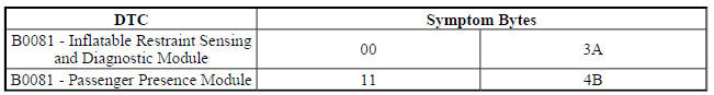
NOTE:
- This system is serviced as a kit (seat foam, module and sensing mat).
Perform a passenger presence system preload procedure whenever a component is replaced. Refer to Passenger Presence System Programming and Setup .
- Both Inflatable Restraint Sensing and Diagnostic Module and Passenger
Presence Module set DTC B0081 but with different symptoms bytes.
Therefore it is important to identify which module has set the DTC B0081.
Use the symptom bytes as a way of identify the correct module to diagnose.
- The Inflatable Restraint Sensing and Diagnostic Module sets a B0081 3A when an incorrect Passenger Presence Module is installed.
- Verify that DTC B0081 3A is not set in the Inflatable Restraint Sensing and Diagnostic Module.
- If DTC B0081 3A is set in the Inflatable Restraint Sensing and Diagnostic Module
Replace the K85 Passenger Presence Module.
- If DTC B0081 3A is not set in the Inflatable Restraint Sensing and Diagnostic Module
NOTE: The Inflatable Restraint Sensing and Diagnostic Module sets a B0081 00 DTC when the Passenger Presence Module sets a DTC B0081 11 or B0081 4B.
- Verify that DTC B0081 11 or DTC B0081 4B is not set in the Passenger Presence Module.
- If DTC B0081 11 or DTC B0081 4B is set in the Passenger Presence Module
Perform the passenger presence system rezero procedure. Refer to Passenger Presence System Programming and Setup .
- If DTC B0081 11 or DTC B0081 4B is not set in the Passenger Presence Module
- All OK.
Repair Instructions
Perform the Diagnostic Repair Verification after completing the repair.
Control Module References for Passenger Presence Module or Inflatable Restraint Sensing and Diagnostic Module replacement, programming and setup
DTC B0083-B0088: Side/front impact sensor
Diagnostic Instructions
- Perform the Diagnostic System Check - Vehicle prior to using this diagnostic procedure.
- Review Strategy Based Diagnosis for an overview of the diagnostic approach.
- Diagnostic Procedure Instructions provides an overview of each diagnostic category.
DTC Descriptors
DTC B0083 01
Left Front Impact Sensor Short to Battery
DTC B0083 02
Left Front Impact Sensor Short to Ground
DTC B0083 04
Left Front Impact Sensor Open
DTC B0083 05
Left Front Impact Sensor High/Voltage Open
DTC B0083 0C
Left Front Impact Sensor Low Current
DTC B0083 39
Left Front Impact Sensor Internal Electronic Failure
DTC B0083 3A
Left Front Impact Sensor Incorrect Component Installed
DTC B0083 71
Left Front Impact Sensor Invalid Serial Data Received
DTC B0084 01
Right Front Impact Sensor Short to Battery
DTC B0084 02
Right Front Impact Sensor Short to Ground
DTC B0084 04
Right Front Impact Sensor Open
DTC B0084 05
Right Front Impact Sensor High/Voltage Open
DTC B0084 0C
Right Front Impact Sensor Low Current
DTC B0084 39
Right Front Impact Sensor Internal Electronic Failure
DTC B0084 3A
Right Front Impact Sensor Incorrect Component Installed
DTC B0084 71
Right Front Impact Sensor Invalid Serial Data Received
DTC B0085 01
Left Front Side Impact Sensor Short to Battery
DTC B0085 02
Left Front Side Impact Sensor Short to Ground
DTC B0085 04
Left Front Side Impact Sensor Open
DTC B0085 05
Left Front Side Impact Sensor High/Voltage Open
DTC B0085 0C
Left Front Side Impact Sensor Low Current
DTC B0085 39
Left Front Side Impact Sensor Internal Malfunction
DTC B0085 3A
Left Front Side Impact Sensor Incorrect Component Installed
DTC B0085 71
Left Front Side Impact Sensor Invalid Serial Data Received
DTC B0086 01
Right Front Side Impact Sensor Short to Battery
DTC B0086 02
Right Front Side Impact Sensor Short to Ground
DTC B0086 04
Right Front Side Impact Sensor Open
DTC B0086 05
Right Front Side Impact Sensor High/Voltage Open
DTC B0086 0C
Right Front Side Impact Sensor Low Current
DTC B0086 39
Right Front Side Impact Sensor Internal Malfunction
DTC B0086 3A
Right Front Side Impact Sensor Incorrect Component Installed
DTC B0086 71
Right Front Side Impact Sensor Invalid Data
DTC B0087 01
Left Rear Side Impact Sensor Short to Battery
DTC B0087 02
Left Rear Side Impact Sensor Short to Ground
DTC B0087 04
Left Rear Side Impact Sensor Open
DTC B0087 05
Left Rear Side Impact Sensor High/Voltage Open
DTC B0087 0C
Left Rear Side Impact Sensor Low Current
DTC B0087 39
Left Rear Side Impact Sensor Internal Malfunction
DTC B0087 3A
Left Rear Side Impact Sensor Incorrect Component Installed
DTC B0087 71
Left Rear Side Impact Sensor Invalid Serial Data Received
DTC B0088 01
Right Rear Side Impact Sensor Short to Battery
DTC B0088 02
Right Rear Side Impact Sensor Short to Ground
DTC B0088 04
Right Rear Side Impact Sensor Open
DTC B0088 05
Right Rear Side Impact Sensor High/Voltage Open
DTC B0088 0C
Right Rear Side Impact Sensor Low Current
DTC B0088 39
Right Rear Side Impact Sensor Internal Malfunction
DTC B0088 3A
Right Rear Side Impact Sensor Incorrect Component Installed
DTC B0088 71
Right Rear Side Impact Sensor Invalid Data
Diagnostic Fault Information

Circuit/System Description
The impact sensors are equipped on vehicles to supplement the Supplemental Inflatable Restraint (SIR) System performance. The impact sensors are electronic and are not part of the deployment loops, but instead provide inputs to the Inflatable Restraint Sensing and Diagnostic Module. The impact sensors can assist in determining the severity of some frontal and side collisions. The Inflatable Restraint Sensing and Diagnostic Module uses the input from the impact sensors to assist in determining the severity of a collision further supporting air bag deployment. If the Inflatable Restraint Sensing and Diagnostic Module determines a deployment is warranted, the Inflatable Restraint Sensing and Diagnostic Module will cause current to flow through the deployment loops deploying the air bags.
Conditions for Running the DTC
Ignition voltage is between 9-16 V.
Conditions for Setting the DTC
Any of the following conditions exist for 10 seconds:
B0083 01, B0084 01, B0085 01, B0086 01, B0087 01, B0088 01
The sensor has been shorted to voltage.
B0083 02, B0084 02, B0085 02, B0086 02, B0087 02, B0088 02
- The sensor has been shorted to ground.
- The sensor current is greater than 23 mA for greater than 5 milliseconds
B0083 04, B0084 04, B0085 04, B0086 04, B0087 04, B0088 04
- The sensor circuit is open.
- The Inflatable Restraint Sensing and Diagnostic Module has not received a message from the sensor for greater than 375 milliseconds.
B0083 05, B0084 05, B0085 05, B0086 05, B0087 05, B0088 05
- The sensor circuit is open or high resistance.
- The Inflatable Restraint Sensing and Diagnostic Module has not received a message from the sensor for greater than 375 milliseconds.
B0083 0C, B0084 0C, B0085 0C, B0086 0C, B0087 0C, B0088 0C
- The sensor has been shorted to ground.
- The sensor current is greater than 23 mA for greater than 5 milliseconds.
B0083 39, B0084 39, B0085 39, B0086 39, B0087 39, B0088 39
- The Inflatable Restraint Sensing and Diagnostic Module has received a Not OK message from the sensor.
- The Inflatable Restraint Sensing and Diagnostic Module has not received a message.
B0083 3A, B0084 3A, B0085 3A, B0086 3A, B0087 3A, B0088 3A
- The Inflatable Restraint Sensing and Diagnostic Module has received identification message from the sensor, which does not match the identification stored in the Inflatable Restraint Sensing and Diagnostic Module memory.
- The Inflatable Restraint Sensing and Diagnostic Module has reset the sensor twice without detecting the correct identification message.
B0083 71, B0084 71, B0085 71, B0086 71, B0087 71, B0088 71
The Inflatable Restraint Sensing and Diagnostic Module has received invalid serial data from the sensor.
Action Taken When the DTC Sets
The Inflatable Restraint Sensing and Diagnostic Module requests the instrument panel cluster to illuminate the AIR BAG indicator.
Conditions for Clearing the DTC
- The condition for setting the DTC no longer exists.
- A history DTC will clear once 100 malfunction-free ignition cycles have occurred.
- An ignition cycle is required for the DTC to go from current to history.
Reference Information
Schematic Reference
SIR Schematics (Encore), SIR Schematics (Encore)
Connector End View Reference
WIRING SYSTEMS AND POWER MANAGEMENT - COMPONENT CONNECTOR END VIEWS - INDEX - ENCORE WIRING SYSTEMS AND POWER MANAGEMENT - COMPONENT CONNECTOR END VIEWS - INDEX - Encore
Description and Operation
Supplemental Inflatable Restraint System Description and Operation
Electrical Information Reference
- Circuit Testing
- Testing for Intermittent Conditions and Poor Connections
- Connector Repairs
- Wiring Repairs
Scan Tool Reference
Control Module References for scan tool information
Circuit/System Verification
NOTE:
- Refer to SIR Service Precautions.
- Inspect all terminals for damage or corrosion when disconnecting connectors. Damage or corrosion in the following requires repair or replacement of the affected component/connector.
- Impact sensor
- Inflatable Restraint Sensing and Diagnostic Module
- Impact sensor wiring harness connector
- Inflatable Restraint Sensing and Diagnostic Module wiring harness connector
- The connector and connector position assurance (CPA) may seat independent of each other. Both the connector and CPA should seat with an audible and/or tactile click. The CPA isolates the shorting-bars within the connector allowing the deployment circuit to operate properly. Replace any CPA that is damaged or missing.
- If the condition is intermittent or cannot be duplicated, disconnect the connectors and add dielectric grease / lubricant (Nyogel 760G or equivalent, meeting GM specification 9986087). This procedure will correct the high resistance condition due to terminal fretting corrosion.
- Verify that DTC B0083-B0088 symptom byte 3A, 39, or 71 is not set as current.
- If DTC B0083-B0088 symptom byte 3A, 39 or 71 is set as current
Replace the appropriate B59 or B63 Impact Sensor.
- If DTC B0083-B0088 symptom byte 3A, 39 or 71 is not set as current
- Verify that DTC B0083-B0088 symptom byte 01, 02, 04, or 05 is not set as current.
- If DTC B0083-B0088 symptom byte 01, 02, 04, or 05 is set as current
Refer to Circuit/System Testing.
- If DTC B0083-B0088 symptom byte 01, 02, 04, 05 is not set as current
- All OK.
Circuit/System Testing
- Ignition OFF, disconnect the harness connector at the appropriate B59 or B63 Impact Sensor, wait 120 seconds.
- Test for less than 10 ohms between the low reference circuit terminal 2 and ground.
- If 10 ohms or greater
- Ignition OFF, disconnect the harness connector at the K36 Inflatable Restraint Sensing and Diagnostic Module.
- Test for less than 2 ohms in the low reference circuit end to end.
- If 2 ohms or greater, repair the open/high resistance in the circuit.
- If less than 2 ohms, replace the K36 Inflatable Restraint Sensing and Diagnostic Module.
- If less than 10 ohms
- Test for greater than 50k ohms between the signal circuit terminal 1 and ground.
- If 50k ohms or less
- Disconnect the harness connector at the K36 Inflatable Restraint Sensing and Diagnostic Module.
- Test for infinite resistance between the signal circuit and ground.
- If less than infinite resistance, repair the short to ground on the circuit.
- If infinite resistance, replace the K36 Inflatable Restraint Sensing and Diagnostic Module.
- If greater than 50k ohms
- Ignition ON, test for less than 1 V between the signal circuit terminal 1 and ground.
- If greater than 1 V
- Disconnect the harness connector at the K36 Inflatable Restraint Sensing and Diagnostic Module.
- Ignition ON, test for less than 1 V between the signal circuit and ground.
- If greater than 1 V, repair the short to voltage on the circuit.
- If less than 1 V, replace the K36 Inflatable Restraint Sensing and Diagnostic Module.
- If less than 1 V
- Disconnect the harness connector at the K36 Inflatable Restraint Sensing and Diagnostic Module.
- Test for less than 2 ohms between the B59 or B63 Impact Sensor signal circuit end to end from the impact sensor terminal 1 and the appropriate K36 Inflatable Restraint Sensing and Diagnostic Module terminal listed below:
- B63LF Side Impact Sensor - Left Front - Terminal 19 X2
- B59L Front Impact Sensor - Left - Terminal 23 X2
- B63RF Side Impact Sensor - Right Front - Terminal 22 X2
- B59R Front Impact Sensor - Right - Terminal 26 X2
- B63LR Side Impact Sensor - Left Rear - Terminal 27 X2
- B63RR Side Impact Sensor - Right Rear - Terminal 30 X2
- If 2 ohms or greater
Repair the open/high resistance in the circuit.
- If less than 2 ohms
- Ignition OFF, connect all harness connectors, press in the CPA (if equipped) until an audible and/or tactile click is heard.
- Ignition ON, clear DTCs. Operate the vehicle within the Conditions for Running the DTC.
- Verify the DTC does not set.
- If the DTC sets
Replace the B59 or B63 Impact Sensor.
- If the DTC does not set
- All OK.
Repair Instructions
Perform the Diagnostic Repair Verification after completing the repair.
- Airbag Side Impact Sensor Replacement (Encore), Airbag Side Impact Sensor Replacement (Encore)
- Inflatable Restraint Remote Impact Sensor Replacement
- Front End Inflatable Restraint Discriminating Sensor Replacement (Encore), Front End Inflatable
- Restraint Discriminating Sensor Replacement (Encore)
- Control Module References for Inflatable Restraint Sensing and Diagnostic Module replacement, programming and setup
DTC B0091: Center front impact sensor
Diagnostic Instructions
- Perform the Diagnostic System Check - Vehicle prior to using this diagnostic procedure.
- Review Strategy Based Diagnosis for an overview of the diagnostic approach.
- Diagnostic Procedure Instructions provides an overview of each diagnostic category.
DTC Descriptors
DTC B0091 01
Center Front Impact Sensor Short to Battery
DTC B0091 02
Center Front Impact Sensor Short to Ground
DTC B0091 04
Center Front Impact Sensor Open Circuit
DTC B0091 05
Center Front Impact Sensor High Voltage/Open
DTC B0091 0C
Center Front Impact Sensor Low Current
DTC B0091 39
Center Front Impact Sensor Internal Malfunction
DTC B0091 3A
Center Front Impact Sensor Incorrect Component Installed
DTC B0091 71
Center Front Impact Sensor Invalid Data
Diagnostic Fault Information

Circuit/System Description
The impact sensors are equipped on vehicles to supplement the supplemental inflatable restraint (SIR) system performance. The impact sensors are electronic and are not part of the deployment loops, but instead provide inputs to the inflatable restraint sensing and diagnostic module. The impact sensors can assist in determining the severity of some frontal and side collisions. The inflatable restraint sensing and diagnostic module uses the input from the impact sensors to assist in determining the severity of a collision further supporting air bag deployment. If the inflatable restraint sensing and diagnostic module determines a deployment is warranted, the inflatable restraint sensing and diagnostic module will cause current to flow through the deployment loops deploying the appropriate air bags. The center front impact sensor and side impact sensors utilize a bidirectional 2-wire circuit. The sensors modulate current on the interface to send identification, state of health, and deployment commands to the inflatable restraint sensing and diagnostic module. The inflatable restraint sensing and diagnostic module serves as a power source and a ground for the sensors. When the ignition is turned ON and input power from the inflatable restraint sensing and diagnostic module is first detected, the sensors respond by performing internal diagnostics and sending an identification to the inflatable restraint sensing and diagnostic module. The inflatable restraint sensing and diagnostic module considers the identification to be valid if the response time is less than 5 seconds. The sensors continually communicate status messages to the inflatable restraint sensing and diagnostic module, which determines if a fault is present in the sensor circuit.
When a fault is detected, the inflatable restraint sensing and diagnostic module may reset the sensors up to 2 times by removing and reapplying power to it. If the fault is still present, the inflatable restraint sensing and diagnostic module will set a DTC.
Conditions for Running the DTC
Ignition voltage is between 9-16 V.
Conditions for Setting the DTC
B0091 01
The inflatable restraint sensing and diagnostic module has detected the center front impact sensor has been shorted to voltage
B0091 02
- The inflatable restraint sensing and diagnostic module has detected the center front impact sensor has been shorted to ground.
- The center front impact sensor current is greater than 23 mA for greater than 5 milliseconds.
B0091 04
- The inflatable restraint sensing and diagnostic module has detected an open/high resistance in the center front impact sensor.
- The inflatable restraint sensing and diagnostic module has not received a message from the center front impact sensor for greater than 375 milliseconds.
B0091 05 and B0091 0C
- The inflatable restraint sensing and diagnostic module has detected the center front impact sensor has been shorted to voltage.
- The inflatable restraint sensing and diagnostic module has detected an open/high resistance in the center front impact sensor.
- The inflatable restraint sensing and diagnostic module has not received a message from the center front impact sensor for greater than 375 milliseconds.
B0091 39
- The inflatable restraint sensing and diagnostic module has received a Not OK (NOK) message from the center front impact sensor.
- The inflatable restraint sensing and diagnostic module has not received a message.
B0091 3A
- The inflatable restraint sensing and diagnostic module has received identification message from the center front impact sensor which does not match the identification stored in the inflatable restraint sensing and diagnostic module memory.
- The inflatable restraint sensing and diagnostic module has reset the center front impact sensor twice without detecting the correct identification message.
B0091 71
The inflatable restraint sensing and diagnostic module has received invalid serial data from the center front impact sensor.
Action Taken When the DTC Sets
- The inflatable restraint sensing and diagnostic module requests the instrument panel cluster to illuminate the AIR BAG indicator.
- The SIR system is disabled and no deployments are allowed.
Conditions for Clearing the DTC
- The condition for setting the DTC no longer exists.
- A history DTC will clear once 100 malfunction-free ignition cycles have occurred.
Reference Information
Schematic Reference
SIR Schematics (Encore), SIR Schematics (Encore)
Connector End View Reference
WIRING SYSTEMS AND POWER MANAGEMENT - COMPONENT CONNECTOR END VIEWS - INDEX - ENCORE WIRING SYSTEMS AND POWER MANAGEMENT - COMPONENT CONNECTOR END VIEWS - INDEX - Encore
Description and Operation
Supplemental Inflatable Restraint System Description and Operation
Electrical Information Reference
- Circuit Testing
- Testing for Intermittent Conditions and Poor Connections
- Wiring Repairs
- Connector Repairs
Scan Tool Reference
Control Module References for scan tool information
Circuit/System Verification
NOTE:
- Refer to SIR Service Precautions.
- Inspect all terminals for damage or corrosion when disconnecting connectors. Damage or corrosion in the following requires repair or replacement of the affected component/connector.
- Front impact sensor
- Side impact sensor
- Inflatable restraint sensing and diagnostic module
- Front impact sensor wiring harness connector
- Side impact sensor wiring harness connector
- Inflatable restraint sensing and diagnostic module wiring harness connector
- The connector and connector position assurance (CPA) may seat independent of each other. Both the connector and CPA should seat with an audible and/or tactile click. The CPA isolates the shorting-bars within the connector allowing the deployment circuit to operate properly. Replace any CPA that is damaged or missing.
- If the condition is intermittent or cannot be duplicated, disconnect the connectors and add dielectric grease / lubricant (Nyogel 760G or equivalent, meeting GM specification 9986087). This procedure will correct the high resistance condition due to terminal fretting corrosion.
- Verify that DTC B0091 symptom byte 39 or 71 is not set as current.
- If DTC B0091 symptom byte 39 or 71 is set as current
Replace the B63 Side Impact Sensor.
- If DTC B0091 symptom byte 39 or 71 is not set as current
- Verify that DTC B0091 symptom byte 3 A is not set as current.
- If DTC B0091 symptom byte 3 A is set as current
Replace the incorrect B63 Side Impact Sensor
- If DTC B0091 symptom byte 3 A is not set as current
- Verify that DTC B0091 symptom byte 01, 02, 04, or 05 is not set as current.
- If DTC B0091 symptom byte 01, 02, 04, or 05 is set as current
Refer to Circuit/System Testing.
- If DTC B0091 symptom byte 01, 02, 04, 05 is not set as current
- All OK.
Circuit/System Testing
- Ignition OFF. Disconnect the harness connector at the B63 Side Impact Sensor. It may take up to 2 min for all vehicle systems to power down.
- Test for less than 10 ohms between the low reference circuit terminal 2 and ground.
If 10 ohms or greater
Ignition OFF, disconnect the X2 harness connector at the K36 Inflatable Restraint Sensing and Diagnostic Module.
Test for less than 2 ohms in the low reference circuit end to end.
- If 2 ohms or greater, repair the open/high resistance in the circuit
- If less than 2 ohms, replace the K36 Inflatable Restraint Sensing and Diagnostic Module.
- If less than 10 ohms
- Test for greater than 50k ohms between the signal circuit terminal 1 and ground.
If 50k ohms or less
- Disconnect the harness connector at the K36 Inflatable Restraint Sensing and Diagnostic Module.
- Test for infinite resistance between the signal circuit and ground.
- If less than infinite resistance, repair the short to ground on the circuit.
- If infinite resistance, replace the K36 Inflatable Restraint Sensing and Diagnostic Module.
- If greater than 50k ohms
- Ignition ON.
- Test for less than 10 V between the signal circuit terminal 1 and ground.
- If 10 V or greater
- Ignition OFF, disconnect the harness connector at the K36 Inflatable Restraint Sensing and Diagnostic Module.
- Ignition ON, test for less than 1 V between the signal circuit and ground.
- If greater than 1 V, repair the short to voltage on the circuit.
- If less than 1 V, replace the K36 Inflatable Restraint Sensing and Diagnostic Module.
- If less than 10 V
- Ignition OFF, disconnect the X2 harness connector at the K36 Inflatable Restraint Sensing and Diagnostic Module.
- Test for less than 2 ohms between the signal circuit end to end from the B63 Side Impact Sensor terminal 1 and the K36 Inflatable Restraint Sensing and Diagnostic Module terminal 23 X2.
If 2 ohms or greater
Repair the open/high resistance in the circuit.
If less than 2 ohms
- Ignition OFF, reconnect all harness connectors, press in the CPA (if equipped) until an audible and/or tactile click is heard.
- Ignition ON, clear DTCs. Operate the vehicle within the Conditions for Running the DTC.
- Verify the DTC does not set.
- If the DTC sets
Replace the B59 Front Impact Sensor.
- If the DTC does not set
- All OK.
Repair Instructions
Perform the Diagnostic Repair Verification after completing the repair.
- Front End Inflatable Restraint Discriminating Sensor Replacement (Encore), Front End Inflatable Restraint Discriminating Sensor Replacement (Encore)
- Control Module References for inflatable restraint sensing and diagnostic module replacement, programming and setup
DTC B1001: Option configuration
Diagnostic Instructions
- Perform the Diagnostic System Check - Vehicle prior to using this diagnostic procedure.
- Review Strategy Based Diagnosis for an overview of the diagnostic approach.
- Diagnostic Procedure Instructions provides an overview of each diagnostic category
DTC Descriptor
DTC B1001 00
Option Configuration
Circuit/System Description
The inflatable restraint sensing and diagnostic module stores a primary data key, which is a 4-digit number.
When the ignition is turned ON, the inflatable restraint sensing and diagnostic module compares this information to the information stored in the body control module (BCM) via serial data. If there is a mismatch between the information stored in the inflatable restraint sensing and diagnostic module and body control module, DTC B1001 will set.
Conditions for Running the DTC
System voltage is between 9-16 V.
Conditions for Setting the DTC
The 4-digit Primary Data Key stored in the inflatable restraint sensing and diagnostic module does not match the 4 digits stored in the body control module.
Action Taken When the DTC Sets
- The inflatable restraint sensing and diagnostic module requests the instrument cluster to illuminate the AIR BAG indicator.
- The inflatable restraint sensing and diagnostic module disables all deployments.
Conditions for Clearing the DTC
The last 4-digit Primary Data Key in the inflatable restraint sensing and diagnostic module matches the last 4 digits stored in the Body Control Module.
Diagnostic Aids
- This DTC is an indication that an incorrect inflatable restraint sensing and diagnostic module is installed in the vehicle, or that the inflatable restraint sensing and diagnostic module and/or the body control module was replaced without reprogramming the body control module with the new information.
- If the inflatable restraint sensing and diagnostic module was previously programmed and DTC B1001 is now set, the setup portion of program was not completed. Proceed to the inflatable restraint sensing and diagnostic module setup portion of the Inflatable Restraint Sensing and Diagnostic Module Programming and Setup
Reference Information
Schematic Reference
SIR Schematics (Encore), SIR Schematics (Encore)
Connector End View Reference
WIRING SYSTEMS AND POWER MANAGEMENT - COMPONENT CONNECTOR END VIEWS - INDEX - ENCORE WIRING SYSTEMS AND POWER MANAGEMENT - COMPONENT CONNECTOR END VIEWS - INDEX - Encore
Description and Operation
Supplemental Inflatable Restraint System Description and Operation
Electrical Information Reference
- Circuit Testing
- Testing for Intermittent Conditions and Poor Connections
- Wiring Repairs
- Connector Repairs
Scan Tool Reference
Control Module References for scan tool information
Circuit/System Verification
- Verify the scan tool K36 Inflatable Restraint Sensing and Diagnostic Module Primary Key Status paramater is Valid.
- If the K36 Inflatable Restraint Sensing and Diagnostic Module Primary Key Status parameter is Invalid
Perform the K36 Inflatable Restraint Sensing and Diagnostic Module setup. Refer to Inflatable Restraint Sensing and Diagnostic Module Programming and Setup .
- If the K36 Inflatable Restraint Sensing and Diagnostic Module Primary Key Status parameter is Valid
- All OK.
Repair Instructions
Perform the Diagnostic Repair Verification after completing the repair.
- SIR/SRS Wiring Repairs
- Control Module References for inflatable restraint sensing and diagnostic module replacement, programming and setup
DTC B1019: System configuration error
Diagnostic Instructions
- Perform the Diagnostic System Check - Vehicle prior to using this diagnostic procedure.
- Review Strategy Based Diagnosis for an overview of the diagnostic approach.
- Diagnostic Procedure Instructions provides an overview of each diagnostic category
DTC Descriptor
DTC B1019 00
System Configuration Error
Circuit/System Description
The inflatable restraint sensing and diagnostic module monitors the number of safety components installed on the vehicle. When the ignition is turned ON, the inflatable restraint sensing and diagnostic module evaluates the number of safety components installed and compares it to the number of components the inflatable restraint sensing and diagnostic module expects to see on the vehicle with its current calibration. If there is a mismatch between detected components and the components programmed with the inflatable restraint sensing and diagnostic module calibration, DTC B1019 will set. The components (if equipped) that the inflatable restraint sensing and diagnostic module will detect include inflatable restraint deployment loops, impact sensors, passenger presence system components, seat position sensors, disable switches, and seat belt switches.
Conditions for Running the DTC
Ignition voltage is between 9-16 V.
Conditions for Setting the DTC
The setup for the inflatable restraint sensing and diagnostic module has not been completed and the inflatable restraint sensing and diagnostic module does not detect the passenger presence system (if equipped), the correct number of sensors, or deployment loops, that is expected with this calibration.
Action Taken When the DTC Sets
- The inflatable restraint sensing and diagnostic module requests the instrument cluster to illuminate the AIR BAG warning indicator.
- The DTC must be cleared before running the setup inflatable restraint sensing and diagnostic module.
- Air bag indicator will continue to flash until inflatable restraint sensing and diagnostic module setup procedure is complete.
Conditions for Clearing the DTC
- The condition for setting the DTC is no longer present.
- A history DTC will clear once 100 malfunction-free ignition cycles have occurred.
Diagnostic Aids
The inflatable restraint sensing and diagnostic module scan tool deployment loop, impact sensor, and passenger presence (if equipped) data will match what the inflatable restraint sensing and diagnostic module has been programmed to expect to see on the vehicle. B1019 DTC will set if a deployment loop or impact sensor is added or removed from the system, or if the passenger presence is not detected.
DTC B1019 will set when an open/high resistance DTC sets for a deployment loop or impact sensor. This causes mismatch between the learned and actual components connected to the inflatable restraint sensing and diagnostic module.
DTC B1019 can set with no other DTCs if an unused deployment loop or impact sensor circuit is shorted to ground. This causes a mismatch between the learned and actual components connected to the inflatable restraint sensing and diagnostic module.
Reference Information
Schematic Reference
- Seat Belt Schematics (Encore) , Seat Belt Schematics (Encore)
- SIR Schematics (Encore), SIR Schematics (Encore)
Connector End View Reference
WIRING SYSTEMS AND POWER MANAGEMENT - COMPONENT CONNECTOR END VIEWS - INDEX - ENCORE WIRING SYSTEMS AND POWER MANAGEMENT - COMPONENT CONNECTOR END VIEWS - INDEX - Encore
Description and Operation
- Seat Belt System Description and Operation
- Supplemental Inflatable Restraint System Description and Operation
Electrical Information Reference
- Circuit Testing
- Testing for Intermittent Conditions and Poor Connections
- Connector Repairs
- Wiring Repairs
Scan Tool Reference
Control Module References for scan tool information
Circuit/System Verification
NOTE:
DTC B1019 can set after the inflatable restraint sensing and diagnostic module has been replaced and/or reprogrammed before the setup procedure is completed. The setup procedure cannot be completed if DTC B1019 is set as current or history. If a short or open is detected in a deployment circuit prior to the setup procedure being performed, the inflatable restraint sensing and diagnostic module will set DTC B1019.
- Ignition ON.
- Verify no other K36 Inflatable Restraint Sensing and Diagnostic Module DTCs are set.
- If other K36 Inflatable Restraint Sensing and Diagnostic Module DTCs are set
Diagnose those DTCs first. Refer to Diagnostic Trouble Code (DTC) List - Vehicle
- If no other K36 Inflatable Restraint Sensing and Diagnostic Module DTCs are set
- Verify the enabled impact sensors identified in the scan tool data list match the number of actual impact sensors installed on the vehicle.
- If the number of enabled impact sensors do not match
- Verify the correct K36 Inflatable Restraint Sensing and Diagnostic Module calibration file is loaded in the K36 Inflatable Restraint Sensing and Diagnostic Module.
- If the K36 Inflatable Restraint Sensing and Diagnostic Module calibration file is correct and the vehicle contains an incorrect number of sensors, identify which sensors are missing to make the vehicle match the K36 Inflatable Restraint Sensing and Diagnostic Module impact sensor calibration scan tool data list.
- If the calibration file is incorrect
- Reprogram the K36 Inflatable Restraint Sensing and Diagnostic Module. Refer to Inflatable Restraint Sensing and Diagnostic Module Programming and Setup
- If the number of enabled impact sensors match
- Verify the enabled deployment loops identified in the scan tool data list match the deployment loops installed on the vehicle.
- If the number of enabled deployment loops do not match
- Verify the correct K36 Inflatable Restraint Sensing and Diagnostic Module calibration file is loaded in the K36 Inflatable Restraint Sensing and Diagnostic Module.
- If the K36 Inflatable Restraint Sensing and Diagnostic Module calibration file is correct and the vehicle contains an incorrect number of loops, identify which deployment loops are missing to make the vehicle match the K36 Inflatable Restraint Sensing and Diagnostic Module impact sensor calibration scan tool data list.
- If the calibration file is incorrect
- Program the K36 Inflatable Restraint Sensing and Diagnostic Module. Refer to Inflatable Restraint Sensing and Diagnostic Module Programming and Setup
- If the number of enabled deployment loops match
- Verify a passenger presence system is equipped on the vehicle.
- If a passenger presence system is not equipped on the vehicle
Replace the K36 Inflatable Restraint Sensing and Diagnostic Module.
- If a passenger presence system is equipped on the vehicle
- Verify the scan tool Passenger Presence System Enable Status parameter is Enabled.
- If the Passenger Presence System Enable Status parameter is not Enabled
Refer to Inflatable Restraint Sensing and Diagnostic Module Programming and Setup
- If the Passenger Presence System parameter is Enabled
- Verify the scan tool Passenger Presence System Learn Status parameter is Learned.
- If the Passenger Presence System Learn Status parameter is not Learned
- Verify the scan tool can communicate with the passenger presence system.
- If the scan tool will not communicate with the passenger presence system, refer to Scan Tool Does Not Communicate with Low Speed GMLAN Device
- If the scan tool communicates
- Ignition OFF, disconnect the scan tool. It may take up to 2 min for all vehicle systems to power down. Ignition ON.
- Verify DTC B1019 is not set as current.
- If the DTC is set as current, refer to Inflatable Restraint Sensing and Diagnostic Module Programming and Setup
- If the DTC is not set as current
- All OK.
- If the Passenger Presence System Learn status is Learned
- Replace the K36 Inflatable Restraint Sensing and Diagnostic Module.
Repair Instructions
Perform the Diagnostic Repair Verification after completing the repair.
- SIR/SRS Wiring Repairs
- Control Module References for inflatable restraint sensing and diagnostic module replacement, programming and setup
Passenger presence system rezeroing
Introduction
The inflatable restraints passenger presence system is a calibrated system that requires re-zeroing or a zero check anytime the seat cushion trim attachments have been removed or the passenger presence system has been replaced. The procedures below are designed to assist in the re-zeroing of the passenger presence system.
Before you start, read these procedures carefully and completely. For further information regarding the passenger presence system refer to Supplemental Inflatable Restraint System Description and Operation.
NOTE: The following procedures must be followed:
- Read this procedure carefully and completely.
- The passenger presence system will not function properly if the passenger presence system re-zeroing procedure is not performed.
- Perform the Diagnostic Repair Verification after successfully completing the re-zeroing procedure to ensure the system is functioning properly.
Passenger Presence System Re-zeroing Procedure
NOTE:
- Before the passenger presence system can be re-zeroed the front passenger seat must be completely empty of all items. The presence of any liquid or items on the front passenger seat will affect the calibration and operation of the passenger presence system.
- DTC B0081 will set if the re-zero system test is performed with:
- An aftermarket seat heater located too close to the sensor mat
- A scan tool, laptop, or other electronic device is in the seat
- The seat is damp or wet
- An object or person is in the seat
- Verify that the temperature is between 32ºF to 100ºF before running a re-zero procedure.
- Verify the seat is completely dry.
- Empty the front outboard passenger seat.
- Verify that all SIR and passenger presence system components, connectors, and connector position assurances are properly connected and mounted.
- Install a scan tool.
- Turn ON the ignition, with the engine OFF.
NOTE:
The presence of current DTCs, except DTC B0081 11 or B0081 4B, will prevent the passenger presence system from re-zeroing and may set additional DTCs.
- With a scan tool, perform the Passenger Presence Sensor Learn procedure.
- If the test fails, confirm that the seat is empty and completely dry. Perform the Passenger Presence Sensor Learn test again. If the test fails again, verify DTC B0081 is not set as current, if the DTC is set refer to Diagnostic Trouble Code (DTC) List - Vehicle . If the test successfully completed, cycle the ignition OFF.
- After the passenger presence system has been successfully re-zeroed, perform the Diagnostic Repair Verification .
SYMPTOMS - SIR
NOTE:
Complete the following steps before using the symptom tables:
- Perform Diagnostic System Check - Vehicle before using the symptom tables in order to verify that all of the following are true:
- There are no DTCs set.
- The inflatable restraint sensing and diagnostic module (SDM) can communicate via the serial data link.
- Review the SIR system description and operation in order to familiarize yourself with the system functions. Refer to Supplemental Inflatable Restraint System Description and Operation.
Visual/Physical Inspection
- Inspect for aftermarket devices which could affect the operation of the SIR system. Refer to Checking Aftermarket Accessories .
- Inspect the easily accessible or visible system components for obvious damage or conditions which could cause the symptom.
Intermittent
Faulty electrical connections or wiring may be the cause of intermittent conditions. Refer to Testing for Intermittent Conditions and Poor Connections .
Symptom List
Refer to Airbag Indicator Malfunction in order to diagnose the symptom.
Airbag indicator malfunction
Diagnostic Instructions
- Perform the Diagnostic System Check - Vehicle prior to using this diagnostic procedure.
- Review Strategy Based Diagnosis for an overview of the diagnostic approach.
- Diagnostic Procedure Instructions provides an overview of each diagnostic category
Circuit/System Description
When the ignition is turned ON, during the bulb check, the driver air bag indicator will flash, and then turn OFF after the bulb check. The inflatable restraint sensing and diagnostic module (SDM) performs diagnostic tests on the SIR system during the bulb check. If any malfunction exists the SDM will request the instrument cluster to illuminate the air bag indicator steady, via serial data. If a preexisting malfunction exists, the air bag indicator will illuminate steady immediately after the ignition is turned ON. If the ignition 1 voltage is outside of the normal operating voltage range of 9-16 V, the inflatable restraint sensing and diagnostic module will command the instrument cluster to illuminate the air bag indicator ON, even with no DTCs present, and then disable all deployment loops.
Diagnostic Aids
- A DTC B1370 may set if the ignition 1 circuit is outside the 9-16 V range.
- A flashing driver air bag indicator is displayed if the inflatable restraint sensing and diagnostic module was programmed but did not fully complete the programming. For a flashing driver air bag indicator, refer to Inflatable Restraint Sensing and Diagnostic Module Programming and Setup .
Reference Information
Schematic Reference
SIR Schematics (Encore), SIR Schematics (Encore)
Connector End View Reference
WIRING SYSTEMS AND POWER MANAGEMENT - COMPONENT CONNECTOR END VIEWS - INDEX - ENCORE WIRING SYSTEMS AND POWER MANAGEMENT - COMPONENT CONNECTOR END VIEWS - INDEX - Encore
Description and Operation
Supplemental Inflatable Restraint System Description and Operation
Electrical Information Reference
- Circuit Testing
- Testing for Intermittent Conditions and Poor Connections
- Connector Repairs
- Wiring Repairs
Scan Tool Reference
Control Module References for scan tool information
Circuit/System Verification
If the driver air bag indicator is flashing, refer to Inflatable Restraint Sensing and Diagnostic Module Programming and Setup .
Circuit/System Testing
- Verify K36 Inflatable Restraint Sensing and Diagnostic Module DTCs are not set.
- If Inflatable Restraint Sensing and Diagnostic Module DTCs are set
Refer to Diagnostic Trouble Code (DTC) List - Vehicle .
- If Inflatable Restraint Sensing and Diagnostic Module DTCs are not set
- Verify the air bag indicator turns ON and OFF when commanding the Instrument Cluster All Indicators ON and OFF with a scan tool.
- If air bag indicator does not turn on or off
If the air bag indicator does not turn ON and OFF as expected, replace the P16 Instrument Cluster
- If air bag indicator does turn on or off
- Replace the K36 Inflatable Restraint Sensing and Diagnostic Module.
Repair Instructions
Perform the Diagnostic Repair Verification after completing the repair.
- SIR/SRS Wiring Repairs
- Control Module References for instrument cluster or inflatable restraint sensing and diagnostic module replacement, programming and setup
Sir disabling and enabling
SIR component location affects how a vehicle should be serviced. There are parts of the SIR system installed in various locations around a vehicle. To find the location of the SIR components refer to Supplemental Inflatable Restraint System Description and Operation.
There are several reasons for disabling the SIR system, such as repairs to the SIR system or servicing a component near or attached to an SIR component. There are several ways to disable the SIR system depending on what type of service is being performed. The following information covers the proper procedures for disabling/enabling the SIR system.
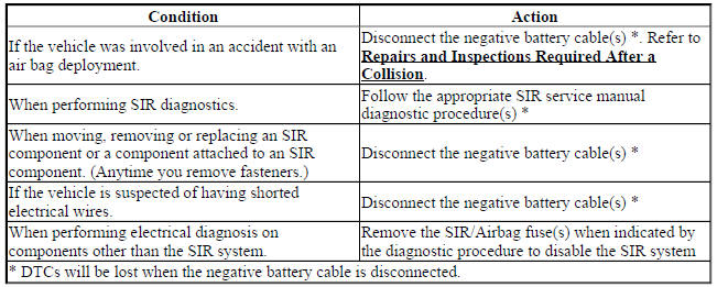
SIR Service Precautions
WARNING: When performing service on or near the SIR components or the SIR wiring, the SIR system must be disabled. Failure to observe the correct procedure could cause deployment of the SIR components. Serious injury can occur. Failure to observe the correct procedure could also result in unnecessary SIR system repairs.
The Inflatable Restraint Sensing and Diagnostic Module (SDM) maintains a reserved energy supply. The reserved energy supply provides deployment power for the air bags if the Inflatable Restraint Sensing and Diagnostic Module loses battery power during a collision. Deployment power is available for as much as 2 minutes after disconnecting the vehicle power. Waiting 2 minutes before working on the system after disabling the SIR system prevents deployment of the air bags from the reserved energy supply.
General Service Instructions
The following are general service instructions which must be followed in order to properly repair the vehicle and return it to its original integrity:
- Do not expose air bags to temperatures above 65ºC (149ºF).
- Verify the correct replacement part number. Do not substitute a component from a different vehicle.
- Use only original GM replacement parts available from your authorized GM dealer. Do not use salvaged parts for repairs to the SIR system.
Discard any of the following components if it has been dropped from a height of 92 cm (3 feet) or greater:
- Inflatable Restraint Sensing and Diagnostic Module (SDM)
- Any air bag
- Driver steering wheel air bag coil
- Any impact sensor
- Seat belt anchor and/or retractor pretensioners
- Passenger presence module and/or occupant sensor
Disabling Procedure - Air Bag Fuse
- Turn the steering wheel so that the vehicles wheels are pointing straight ahead.
- Place the ignition in the OFF position.
WARNING: The SDM may have more than one fused power input. To ensure there is no unwanted SIR deployment, personal injury, or unnecessary SIR system repairs, remove all fuses supplying power to the SDM. With all SDM fuses removed and the ignition switch in the ON position, the AIR BAG warning indicator illuminates. This is normal operation, and does not indicate a SIR system malfunction.
- Locate and remove the fuse(s) supplying power to the Inflatable Restraint Sensing and Diagnostic Module. Refer to SIR Schematics (Encore), SIR Schematics (Encore), or Electrical Center Identification Views (Encore) , Electrical Center Identification Views (Encore) .
- Wait 2 minutes before working on the system.
Enabling Procedure - Air Bag Fuse
- Place the ignition in the OFF position.
- Install the fuse(s) supplying power to the Inflatable Restraint Sensing and Diagnostic Module. Refer to SIR Schematics (Encore), SIR Schematics (Encore), or Electrical Center Identification Views (Encore) , Electrical Center Identification Views (Encore) .
- Turn the ignition switch to the ON position. The AIR BAG indicator will illuminate or flash then turn OFF.
- Perform the Diagnostic System Check - Vehicle if the AIR BAG warning indicator does not operate as described. Refer to Diagnostic System Check - Vehicle .
Disabling Procedure - Negative Battery Cable
- Turn the steering wheel so that the vehicles wheels are pointing straight ahead.
- Place the ignition in the OFF position.
- Disconnect the negative battery cable from the battery. Refer to Battery Negative Cable Disconnection and Connection .
- Wait 2 minutes before working on system.
Enabling Procedure - Negative Battery Cable
- Place the ignition in the OFF position.
- Connect the negative battery cable to the battery. Refer to Battery Negative Cable Disconnection and Connection .
- Turn the ignition switch to the ON position. The AIR BAG indicator will illuminate or flash then turn OFF.
- Perform the Diagnostic System Check - Vehicle if the AIR BAG warning indicator does not operate as described. Refer to Diagnostic System Check - Vehicle .
READ NEXT:
 Supplemental Inflatable Restraints - Repair instructions
Sir service precautions
General Service Instructions
WARNING: When performing service on or near the SIR components or
the SIR
wiring, the SIR system must be disabled. Refer to SIR Disabling and
Enab
Supplemental Inflatable Restraints - Description and operation
SUPPLEMENTAL INFLATABLE RESTRAINT SYSTEM DESCRIPTION AND OPERATION
SIR System Overview
The supplemental inflatable restraint (SIR) system supplements the protection
offered by the seat belts. The SIR
SEE MORE:
Tire Chains
Warning
Do not use tire chains. There is
not enough clearance. Tire chains
used on a vehicle without the
proper amount of clearance can
cause damage to the brakes,
suspension, or other vehicle
parts. The area damaged by the
tire chains could cause loss of
control and a crash.
Use another type of tr
Repair instructions
Front disc brake pads replacement
Removal Procedure
WARNING: Refer to Brake Dust Warning .
WARNING: Refer to Brake Fluid Irritant Warning .
NOTE: Always replace disc brake pads in axle sets.
Inspect the fluid level in the brake master cylinder reservoir.
If the brake fluid level is midway between
