Buick Encore: Engine Mechanical - 1.4L - Description and operation
Engine component description
Cylinder Block
The cylinder hollow frame structured in-line 4 cylinder. The block has 5 crankshaft bearings with the thrust bearing located on the third bearing from the front of the engine.
Crankshaft
The crankshaft is a steel crankshaft. It is supported in 5 main journals with main bearings which have oil clearance for lubrication. The 3rd bearing is the thrust bearing which controls the proper axial end play of the crankshaft. A harmonic damper is used to control torsional vibration.
Oil Pump
The engine is equipped with a variable oil pump. The oil pump is integrated into the engine front cover and provides different oil pressure values depending on the engine speed.
Oil Pan
The oil pan is a structural aluminum oil pan with transmission attachment points. The oil suction gallery for the oil pump is integrated into the oil pan.
Piston and Connecting Rod
The pistons are aluminum pistons. The connecting rods are made of fractured steel. The piston pin is floating in piston bore and shrinked in connecting rod.
Cylinder Head
This cylinder head is a double over head camshaft (DOHC) type and has 2 camshafts that open 4 valves per cylinder with hydraulic valve lash adjusters and hydraulic valve lash adjuster arms. The cylinder head is made of cast aluminum alloy for better strength and hardness while remaining light weight. The combustion chamber of the cylinder head is designed for increasing of squish and swirl efficiency to help maximize gasoline combustion efficiency.
Camshaft Drive with Variable Camshaft Timing
A timing chain is used for camshaft drive. There is a tensioner to control the tension of the chain. The engine is equipped with a variable camshaft timing system. The camshaft adjuster will readjust itself depending on the engine speed. The valve timing readjusts to reduce fuel consumption and provide optimal power and torque.
Intake Manifold
The intake manifold provides the air flow passage to the combustion chambers through the throttle body. The intake manifold along with the throttle body have an effect on engine torque, power, noise, driveability, emission, fuel economy and performance. The intake manifold is made of plastic for better strength with maintaining a light weight.
Turbocharger
The turbocharger consists of turbine and compressor on a common shaft. The shaft bearing is constructed to higher rotation speed and lubricated by engine oil. The turbocharger is water cooled for improved durability.
The turbine wheel is driven by exhaust emissions. The compressor wheel compresses the intake air. A bypass valve (Wastegate) regulates the charging pressure for generating a high pressure at low speed as well. At a defined charging pressure it regulates the way of the exhaust emission on bypassing the turbine wheel. The Wastegate valve is controlled pneumatic and electric from the pressure in the intake manifold. The pressure of exhaust emission is reduced by opening the Wastegate thereby reducing the intake pressure.
Lubrication description
General Lubrication Description
.gif)
Fig. 483: Lubrication System Components
Oil is applied under pressure to the crankshaft bearings (6), connecting rod bearings (7), camshaft bearings (2) and hydraulic lash adjusters (3). In addition the variable oil pump (9), variable camshaft phaser (1), and hydraulic chain tensioner (14) are supplied with pressurized oil. Oil is sucked from the oil pan through the fixed screen into the variable vane type oil pump. The pump is integrated in the front cover and directly driven by the crankshaft. Also integrated into the front cover is a pressure relieve valve (8) that opens when the oil pressure is too high at a cold start. When that valve is open some oil flows directly into the oil pan. Normally the pressurized oil passes into the engine oil gallery leading through the oil cooler (5) to the oil filter assembly (4).
The oil is cleaned by passing the filter from the outer to the inner side of the filter. Then the oil flows into the main oil gallery. A filter by-pass valve in the oil filter ensures continues oil flow in case the oil filter should be restricted by more than 1.7 bar. From the oil filter the oil is distributed to the crankshaft bearings, oil pump displacement control chamber (10) and cylinder head feed (11). The connecting rod bearings are supplied by oil flow passages through the crankshaft connecting the main journals to the rod journals. A groove around each upper main bearing furnishes oil to the drilled crankshaft passages. In the cylinder head the oil is distributed to the variable camshaft phasers, chain tensioner, oil pressure switch (12) and through the restrictor orifice (13) into the camshaft feed oil gallery. From there the hydraulic valve lifters and camshaft bearings are supplied with oil.
Variable Oil Pump Description
The engine is equipped with a variable displacement vane oil pump. It is indirect regulated by the oil pressure out of the main oil gallery. The purpose of this indirect regulation is to keep a defined maximum pressure in the main oil gallery independent of the individual pressure drop between the pump outlet, the main gallery inlet, and the various engine components. The purpose of the variable displacement is to reduce the power consumption of the pump to reduce the overall fuel consumption of the engine. The oil flow of a static displacement oil pump is linear to the speed of the pump. This would lead to a too high oil pressure after a certain engine speed (ca. 1000 rpm at cold oil temperature, ca. 3000 rpm at hot oil temperatures). To reduce that high oil pressure normal pumps have a relieve valve: a portion of the pressurized, already pumped oil is fed back to the intake of the pump. This is waste of power. The oil flow of a Variable Displacement Vane Pump (VDVP) as used in Fam 0 Gen 3 is linear to the speed and to the excentricity of the rotor to the slide. The slide is moveable, so it is possible to reduce the oil flow for a given speed by reducing the excentricity. With a lower flow the oil pressure is reduced; pump oil flow equals now engine oil flow.
Cleanliness and care
An automobile engine is a combination of many of the following surfaces:
- Machined
- Honed
- Polished
- Lapped
The tolerances of these surfaces are measured in the ten-thousandths of an inch. When you service any internal engine part, cleanliness and care are important. Apply a liberal coating of engine oil to the friction areas during assembly in order to protect and lubricate the surfaces on initial operation. Throughout this section, practice proper cleaning and protection procedures to the machined surfaces and to the friction areas.
Whenever you remove the valve train components, keep the components in order. Follow this procedure in order to install the components in the same locations and with the same mating surfaces as when removed.
WARNING: Refer to Battery Disconnect Warning .
Disconnect the negative battery cables before you perform any major work on the engine.
USE OF ROOM TEMPERATURE VULCANIZING (RTV) AND ANAEROBIC SEALANT
Pipe Joint Compound
NOTE: Three types of sealer are commonly used in engines. These are RTV sealer, anaerobic gasket eliminator sealer, and pipe joint compound. The correct sealer and amount must be used in the proper location to prevent oil leaks. DO NOT interchange the 3 types of sealers. Use only the specific sealer or the equivalent as recommended in the service procedure.
- Pipe joint compound is a pliable sealer that does not completely harden. This type sealer is used where 2 non-rigid parts, such as the oil pan and the engine block, are assembled together.
- Do not use pipe joint compound in areas where extreme temperatures are expected. These areas include: exhaust manifold, head gasket, or other surfaces where gasket eliminator is specified.
- Follow all safety recommendations and directions that are on the container. To remove the sealant or the gasket material.
- Apply the pipe joint compound to a clean surface. Use a bead size or quantity as specified in the procedure. Run the bead to the inside of any bolt holes. Do not allow the sealer to enter any blind threaded holes, as it may prevent the bolt from clamping properly.
- Apply a continuous bead of pipe joint compound to one sealing surface. Sealing surfaces to be resealed must be clean and dry.
- Tighten the bolts to specifications. Do not overtighten.
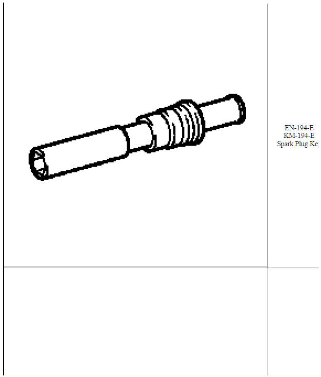
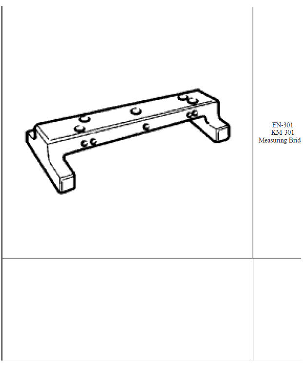
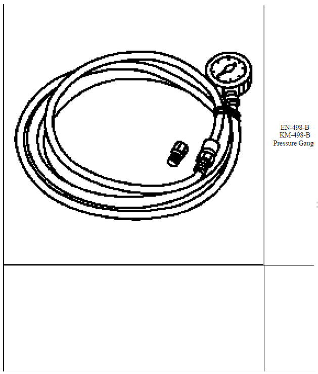
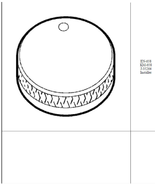
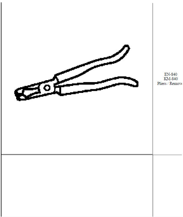
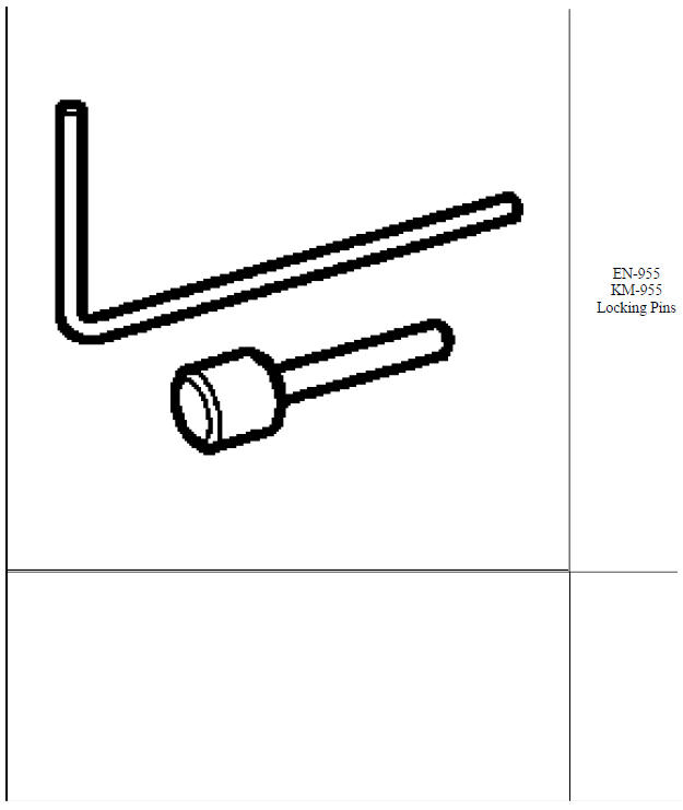
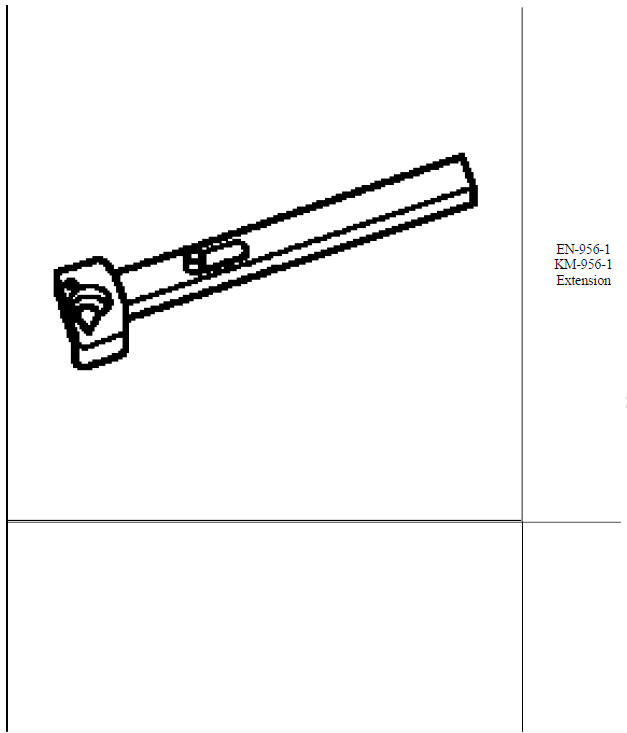
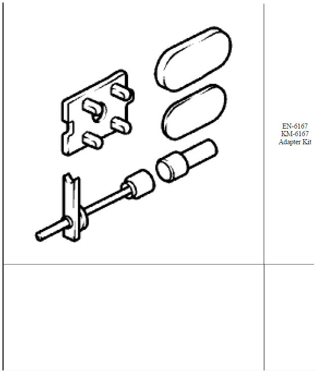
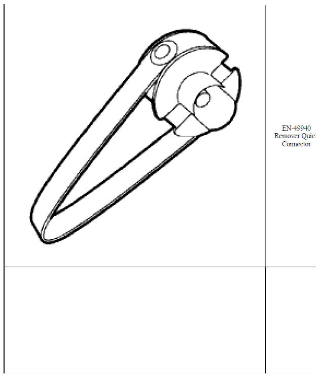
Special tools and equipment
SPECIAL TOOLS


READ NEXT:
 Engine Controls and Fuel - 1.4L - Description and operation
Camshaft actuator system description
Camshaft Actuator System Overview
Fig. 1: Identifying Camshaft Actuator System Components
The camshaft actuator system enables the engine control module (ECM
Engine controls and fuel - 1.4l - Diagnostic information and procedures
DTC P0010, P0013, OR P2088-P2091
Diagnostic Instructions
Perform the Diagnostic System Check - Vehicle prior to using this
diagnostic procedure.
Review Strategy Based Diagnosis for an overview of
SEE MORE:
Malfunction Indicator Lamp (Check Engine Light - Capless)
This light is part of the vehicle's
emission control on-board
diagnostic system. If this light is on
while the engine is running, a
malfunction has been detected and
the vehicle may require service. The
light should come on to show that it
is working when the ignition is in
Service Mode. See Ignitio
Communication interface module scan tool information
Telematics Communication Interface Control Module Scan Tool Data
Parameters
Telematics Communication Interface Control Module Scan Tool Output
Controls
SEAT MEMORY CONTROL MODULE SCAN TOOL INFORMATION
Seat Position Scan Tool Data Parameters
Mirror Memory Scan Tool Data Parameters
Lef
