Buick Encore: Engine controls and fuel - 1.4l - Diagnostic information and procedures
DTC P0010, P0013, OR P2088-P2091
Diagnostic Instructions
- Perform the Diagnostic System Check - Vehicle prior to using this diagnostic procedure.
- Review Strategy Based Diagnosis for an overview of the diagnostic approach.
- Diagnostic Procedure Instructions provides an overview of each diagnostic category
DTC Descriptor
DTC P0010
Intake Camshaft Position Actuator Solenoid Valve Control Circuit
DTC P0013
Exhaust Camshaft Position Actuator Solenoid Valve Control Circuit
DTC P2088
Intake Camshaft Position Actuator Solenoid Valve Control Circuit High Voltage
DTC P2089
Intake Camshaft Position Actuator Solenoid Valve Control Circuit High Voltage
DTC P2090
Exhaust Camshaft Position Actuator Solenoid Valve Control Circuit Low Voltage
DTC P2091
Exhaust Camshaft Position Actuator Solenoid Valve Control Circuit High Voltage
Diagnostic Fault Information
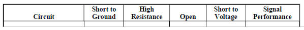
Circuit/System Description
The camshaft position actuator system enables the Engine Control Module (ECM) to change the timing of the camshafts while the engine is operating. The Camshaft Position Actuator Solenoid Valve signal from the ECM is pulse width modulated (PWM). The ECM controls the Camshaft Position Actuator Solenoid Valve duty cycle by controlling the amount of solenoid valve On time. The Camshaft Position Actuator Solenoid Valve controls the advance or the retard of each camshaft. The Camshaft Position Actuator Solenoid Valve controls the oil flow that applies the pressure to advance or retard the camshafts.
The ECM controls the Camshaft Position Actuator Solenoid Valve by suppling a 12 V pulse width modulated (PWM) signal. The ECM supplies a ground to the low reference circuit.
Conditions for Running the DTC
- The ignition voltage is greater than 11 V
- The ignition switch is in the crank or run position.
- The ECM has commanded the Camshaft Position Actuator Solenoid Valve On.
- The DTCs run continuously once the above conditions are met.
Conditions for Setting the DTC
The ECM detects that the commanded state of the driver and the actual state of the control circuit do not match for greater than 5 s.
Action Taken When the DTC Sets
DTCs P0010, P0013, P2088, P2089, P2090 and P2091 are type B DTCs.
Conditions for Clearing the DTC
DTCs P0010, P0013, P2088, P2089, P2090 and P2091 are type B DTCs.
Diagnostic Aids
If the condition is intermittent, move the related harnesses and connectors, with the engine operating, while monitoring the scan tool Circuit Test Status parameters for the component. The Circuit Test Status parameters change from OK or Not Run to Malfunction if there is a condition with the circuit or a connection.
Reference Information
Schematic Reference
Engine Controls Schematics (Encore) , Engine Controls Schematics (Encore)
Connector End View Reference
WIRING SYSTEMS AND POWER MANAGEMENT - COMPONENT CONNECTOR END VIEWS - INDEX - ENCORE WIRING SYSTEMS AND POWER MANAGEMENT - COMPONENT CONNECTOR END VIEWS - INDEX - Encore
Component View Reference
Powertrain Component Views
Description and Operation
Camshaft Actuator System Description
Electrical Information Reference
- Circuit Testing
- Connector Repairs
- Testing for Intermittent Conditions and Poor Connections
- Wiring Repairs
DTC Type Reference
Powertrain Diagnostic Trouble Code (DTC) Type Definitions (LUV) , Powertrain Diagnostic Trouble Code (DTC) Type Definitions (2H0)
Scan Tool Reference
Control Module References for scan tool information
Circuit/System Verification
NOTE: If a crankshaft or camshaft position sensor DTC is set, the Camshaft Position Actuator output control will not function.
- Ignition On.
- Verify DTC P0335, P0336, P0340, or P0341 is not set.
- If any of the DTCs are set
Refer to Diagnostic Trouble Code (DTC) List - Vehicle .
- If none of the DTCs are set
- Engine idling, command the Camshaft Position Actuator to 10º while observing the following control circuit status parameters with a scan tool:
- Exhaust or Intake Camshaft Position Actuator Solenoid Valve Control Circuit Open Test Status
- Exhaust or Intake Camshaft Position Actuator Solenoid Valve Control Circuit Low Voltage Test Status
- Intake or Exhaust Camshaft Position Actuator Solenoid Valve Control Circuit High Voltage Test Status
- If Malfunction is displayed
Refer to Circuit/System Testing
- If Malfunction is not displayed
- Operate the vehicle within the Conditions for Running the DTC. You may also operate the vehicle within the conditions that you observed from the Freeze Frame/Failure Records data.
- Verify the DTC does not set.
- If the DTC sets
Refer to Circuit/System Testing.
- If the DTC does not set
- All OK.
Circuit/System Testing
- Ignition Off and all vehicle systems Off, disconnect the appropriate harness connector at the camshaft position actuator solenoid valve. It may take up to 2 minutes for all vehicle systems to power down.
- Test for less than 5 ohms between the low reference circuit terminal 1 and ground.
- If 5 ohms or greater
- Ignition Off, disconnect the harness connector at the K20 Engine Control Module.
- Test for less than 2 ohms in the low reference circuit end to end.
- If 2 ohms or greater, repair the open/high resistance in the circuit.
- If less than 2 ohms, replace the K20 Engine Control Module.
- If less than 5 ohms
- Test for less than 5 ohms between the control circuit terminal 2 and ground.
- If 5 ohms or greater
- Ignition Off, disconnect the harness connector at the K20 Engine Control Module.
- Test for less than 2 ohms in the control circuit end to end.
- If 2 ohms or greater, repair the open/high resistance in the circuit.
- If less than 2 ohms, replace the K20 Engine Control Module.
- If less than 5 ohms
- Ignition On.
NOTE: A test lamp must be used for this test. The control circuit is pulled-up to a low current voltage, 1.5-3.5 V on the control circuit is normal.
- Verify that a test lamp does not illuminate between the control circuit terminal 2 and ground.
- If the test lamp illuminates
- Ignition Off, disconnect the harness connector at the K20 Engine Control Module, ignition On.
- Test for less than 1 V between the control circuit and ground.
- If 1 V or greater, repair the short to voltage on the circuit
- If less than 1 V, replace the K20 Engine Control Module
- If the test lamp does not illuminate
- Remove the test lamp.
- Connect the DMM black lead to the control circuit terminal 2. Connect the DMM red lead to B+. Set the DMM on the diode setting. Command the CMP actuator solenoid On and Off with a scan tool. The DMM should transition from OL when commanded Off to less than 1 V when commanded On.
- If the circuit voltage does not correspond to the specified values
- Ignition Off, disconnect the harness connector at the K20 Engine Control Module.
- Test for less than 2 ohms in the control circuit end to end.
- If 2 ohms or greater, repair the open/high resistance or short to ground in the circuit
- If less than 2 ohms, replace the K20 Engine Control Module
- If the circuit voltage corresponds to the specified values
- Test or replace the appropriate camshaft position actuator solenoid valve.
Component Testing
- Ignition Off, disconnect the harness connector at the appropriate Q6 Camshaft Position Actuator Solenoid Valve.
- Test for 7-12 ohms between the control terminal 2 and the low reference circuit terminal 1.
- If not between 7-12 ohms
Replace the Q6 Camshaft Position Actuator Solenoid Valve.
- If between 7-12 ohms
- Test for infinite resistance between each terminal and the Q6 Camshaft Position Actuator Solenoid Valve housing
- If less than infinite resistance
Replace the Q6 Camshaft Position Actuator Solenoid Valve.
- If infinite resistance
- All OK.
Repair Instructions
Perform the Diagnostic Repair Verification after completing the repair.
- Camshaft Position Actuator Solenoid Valve Replacement
- Control Module References for Engine Control Module replacement, programming and setup.
DTC P0011 OR P0014
Diagnostic Instructions
- Perform the Diagnostic System Check - Vehicle prior to using this diagnostic procedure.
- Review Strategy Based Diagnosis for an overview of the diagnostic approach.
- Diagnostic Procedure Instructions provides an overview of each diagnostic category.
DTC Descriptors
DTC P0011
Intake Camshaft Position System Performance
DTC P0014
Exhaust Camshaft Position System Performance
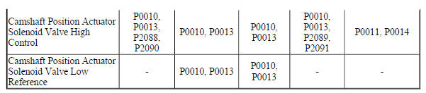
Diagnostic Fault Information
.jpg)
Circuit/System Description
The camshaft position (CMP) actuator system enables the engine control module (ECM) to change the timing of the camshafts while the engine is operating. The camshaft position actuator solenoid valves are operated hydraulically in order to change the angle of the camshaft relative to crankshaft position. The camshaft position actuator solenoid valves are controlled by the engine control module (ECM). The ECM sends a pulse width modulated signal to the camshaft position actuator solenoid valves. The camshaft position actuator solenoid valves control the amount of engine oil flow that applies the pressure to advance or retard the camshafts.
Conditions for Running the DTC
- DTC P0010, P0013, P0016, P0017, P0335, P0340, P0341, P0365, or P0366 is not set.
- The engine is running.
- The ignition voltage is between 11-32 V.
- The camshaft position actuator is enabled.
- The rate of change in the camshaft position is less than 3º for 4 s.
- DTCs P0011 and P0014 runs continuously once the above conditions are met for greater than 0.1 s.
Conditions for Setting the DTC
The ECM detects a difference between the camshaft position angle and the desired camshaft position angle is greater than 6 to 10º based on engine coolant temperature and engine speed.
Action Taken When the DTC Sets
DTCs P0011 and P0014 are Type B DTCs.
Conditions for Clearing the DTC
DTCs P0011 and P0014 are Type B DTCs.
Diagnostic Aids
- The engine oil condition has a major impact on the camshaft actuator system.
- A low oil level condition may set this DTC. The engine may require an oil change. Inquire with the customer when the last oil change was performed. You may also monitor the scan tool Engine Oil Life Remaining parameter. Advise the customer an oil change may be required.
- Inspect the engine for any recent engine mechanical repairs. An incorrectly installed camshaft, camshaft actuator, or timing belt can cause this DTC to set.
- A resistance greater than 8 ohms on the camshaft position actuator solenoid valve control circuit may set this DTC. If you suspect high resistance, ground the control circuit while the engine is idling. The scan tool Intake or Exhaust Camshaft Position Actuator Solenoid Valve Control Circuit Low Voltage Test Status should display Malfunction. If the parameter displays OK, test the control circuit for high resistance.
Reference Information
Schematic Reference
ENGINE CONTROLS SCHEMATICS (Encore) ENGINE CONTROLS SCHEMATICS (Encore)
Connector End View Reference
WIRING SYSTEMS AND POWER MANAGEMENT - COMPONENT CONNECTOR END VIEWS - INDEX - ENCORE WIRING SYSTEMS AND POWER MANAGEMENT - COMPONENT CONNECTOR END VIEWS - INDEX - Encore
Component View Reference
Powertrain Component Views
Description and Operation
Camshaft Actuator System Description
Electrical Information Reference
- Circuit Testing
- Connector Repairs
- Testing for Intermittent Conditions and Poor Connections
- Wiring Repairs
DTC Type Reference
Powertrain Diagnostic Trouble Code (DTC) Type Definitions (LUV) , Powertrain Diagnostic Trouble Code (DTC) Type Definitions (2H0)
Scan Tool Reference
Control Module References for scan tool information
Circuit/System Verification
NOTE:
- The engine oil level and the oil pressure are critical to the correct operation of the camshaft position actuator system. Verify that the engine has the correct oil level and the correct oil pressure before continuing with this diagnostic.
- The engine oil condition has a major impact on the camshaft actuator
system. Debris in the oil can interfere with the camshaft position
actuator solenoid and the mechanical camshaft actuator operation.
Inspect for dirty or degraded crankcase oil. The engine may require an oil change. Inquire with the customer when the last oil change was performed. You may also monitor the scan tool Engine Oil Life Remaining parameter. Advise the customer an oil change may be required.
- Ignition On.
- Verify the correct engine oil level and pressure. Refer to OIL PRESSURE DIAGNOSIS AND TESTING
- If the oil level and the oil pressure are not correct
Repair as necessary
- If the oil level and the oil pressure are correct
NOTE: If a crankshaft or camshaft position sensor DTC is set, the scan tool Camshaft Position Actuator output control will not function.
- Verify DTC P0010, P0013, P0016, P0017, P0335, P0336, P0340, P0341, P0365, P0366, P2088, P2089, P2090 or P2091 is not set.
- If any of the DTCs are set
Refer to Diagnostic Trouble Code (DTC) List - Vehicle for further diagnosis.
- If none of the DTCs are set
- Engine idling.
- Verify the scan tool parameters are less than 2º in each of the commanded states when commanding the Camshaft Position Actuator from 0-20º and back to 0º with the scan tool.
- Intake Camshaft Position Variance
- Exhaust Camshaft Position Variance
- Intake Camshaft Position Variance
- Exhaust Camshaft Position Variance
- If 2º or greater
Refer to Circuit/System Testing.
- If less than 2º
- Verify that DTC P0011 or P0014 is not set.
- If any of the DTCs are set
Refer to Circuit/System Testing.
- If none of the DTCs set
- Operate the vehicle within the Conditions for Running the DTC. You may also operate the vehicle within the conditions that you observed from the Freeze Frame/Failure Records data.
- Verify the DTC does not set.
- If the DTC sets
Refer to Circuit/System Testing.
- If the DTC does not set
- All OK.
Circuit/System Testing
- Ignition Off, disconnect the harness connector at the appropriate Q6 Camshaft Position Actuator Solenoid Valve. It may take up to 2 minutes for all vehicle systems to power down.
- Test for less than 5 ohms between the low reference circuit terminal 1 and ground.
- If 5 ohms or greater
- Ignition Off, disconnect the harness connector at the K20 Engine Control Module.
- Test for less than 2 ohms in the low reference circuit end to end.
- If 2 ohms or greater, repair the open/high resistance in the circuit.
- If less than 2 ohms, replace the K20 Engine Control Module.
- If less than 5 ohms
- Ignition On.
NOTE: A test lamp must be used for this test. The control circuit is pulled-up to a low current voltage, 1.5-4.5 V on the control circuit is normal.
- Verify that a test lamp does not illuminate between the control circuit terminal 2 and ground.
- If the test lamp illuminates
- Ignition Off, disconnect the harness connector at the K20 Engine Control Module, ignition On.
- Test for less than 1 V between the control circuit and ground.
- If 1 V or greater, repair the short to voltage on the circuit.
- If less than 1 V, replace the K20 Engine Control Module.
- If the test lamp does not illuminate
- Remove the test lamp.
- Verify the scan tool parameters listed below do not display Malfunction when commanding the appropriate Camshaft Position Actuator Solenoid Valve On with a scan tool.
- Intake Camshaft Position Actuator Solenoid Valve Control Circuit Low Voltage Test Status
- Exhaust Camshaft Position Actuator Solenoid Valve Control Circuit Low Voltage Test Status
- Intake Camshaft Position Actuator Solenoid Valve Control Circuit Low Voltage Test Status
- Exhaust Camshaft Position Actuator Solenoid Valve Control Circuit Low Voltage Test Status
- If Malfunction is displayed
- Ignition Off, disconnect the harness connector at the K20 Engine Control Module.
- Test for less than 2 ohms in the control circuit end to end.
- If 2 ohms or greater, repair the open/high resistance or short to ground in the circuit.
- If less than 2 ohms, replace the K20 Engine Control Module.
- If Malfunction is not displayed
- Ignition Off, remove the Q6 Camshaft Position Actuator Solenoid Valve.
- Verify the conditions listed below do not exist with the Q6 Camshaft Position Actuator Solenoid Valve:
- Torn, restricted, mis-positioned, or missing screens.
- Engine oil leak between the oil sealing lands of the solenoid. Inspect the lands of the solenoid for nicks.
- Oil seepage at the solenoid connector.
- If a condition is found
Replace the Q6 Camshaft Position Actuator Solenoid Valve.
- If a condition is not found
NOTE: After swapping toe solenoids, install jumper wires to the appropriate terminals of the harness connectors and the solenoids.
- Ignition Off, swap the Q6 Camshaft Position Actuator Solenoid Valve with the Q6 Camshaft Position Actuator Solenoid Valve that is operating correctly.
- Engine idling.
- Verify the scan tool Camshaft Position Variance parameter is less than 2º in each of the commanded states when commanding the Camshaft Position Actuator from 0-20º and back to 0º with a scan tool.
- If 2º or greater
Replace the mechanical camshaft position actuator.
- If less than 2º
- Test or replace the Q6 Camshaft Position Actuator Solenoid Valve.
Component Testing
- Ignition Off, disconnect the harness connector at the appropriate Q6 Camshaft Position Actuator Solenoid Valve.
- Test for 7-12 ohms between the control terminal 2 and the low reference circuit terminal 1.
- If not between 7-12 ohms
Replace the Q6 Camshaft Position Actuator Solenoid Valve.
- If between 7-12 ohms
- Test for infinite resistance between each terminal and the Q6 Camshaft Position Actuator Solenoid Valve housing.
- If less than infinite resistance
Replace the Q6 Camshaft Position Actuator Solenoid Valve.
- If infinite resistance
- All OK
Repair Instructions
Perform the Diagnostic Repair Verification after completing the repair.
- Camshaft Position Actuator Solenoid Valve Replacement
- Control Module References for ECM replacement, programming and setup
DTC P0016 OR P0017
Diagnostic Instructions
- Perform the Diagnostic System Check - Vehicle prior to using this diagnostic procedure.
- Review Strategy Based Diagnosis for an overview of the diagnostic approach.
- Diagnostic Procedure Instructions provides an overview of each diagnostic category.
DTC Descriptors
DTC P0016
Crankshaft Position - Intake Camshaft Position Not Plausible
DTC P0017
Crankshaft Position - Exhaust Camshaft Position Not Plausible
Circuit/System Description
The engine control module (ECM) uses the crankshaft position sensor, intake camshaft position sensor, and the exhaust camshaft position sensor information to monitor the correlation between the crankshaft, intake camshaft, and exhaust camshaft position.
Conditions for Running the DTC
- DTCs P0335, P0336, P0340, P0341, P0365, P0366, P0641, or P0651 is not set
- The engine is running.
- The camshaft position actuator solenoid valves are in the parked position.
The DTCs run continuously once the above conditions are met.
Conditions for Setting the DTC
The ECM detects a camshaft to crankshaft misalignment. The DTC sets if the crankshaft position sensor signal is 10 degrees before or after the normal position in relation to the crankshaft angle while the engine is running.
Action Taken When the DTC Sets
DTCs P0016 and P0017 are Type B DTCs.
Conditions for Clearing the DTC
DTCs P0016 and P0017 are Type B DTCs.
Diagnostic Aids
The following conditions can also set the DTCs:
- A short to ground in a camshaft position actuator solenoid valve control circuit.
- Crankshaft end play out of specification.
- A crankshaft reluctor wheel that has moved in relationship to top dead center (TDC).
Reference Information
Description and Operation
Camshaft Actuator System Description
DTC Type Reference
Powertrain Diagnostic Trouble Code (DTC) Type Definitions (LUV) , Powertrain Diagnostic Trouble Code (DTC) Type Definitions (2H0)
Scan Tool Reference
Control Module References for scan tool information
Circuit/System Verification
- Ignition ON.
- Verify DTC P0335, P0336, P0340, P0341, P0365, P0366, P0641 or P0651 is not set.
- If any of the DTCs are set
Refer to Diagnostic Trouble Code (DTC) List - Vehicle .
- If none of the DTCs are set
- Engine Running at normal operating temperature.
- Verify DTC P0016 or P0017 is not set.
- If the DTC is set
Inspect for the following and repair as necessary:
- A Q6 Camshaft Position Actuator Solenoid Valve that is stuck in the full advance or retard position.
- The correct installation of the Q6 Camshaft Position Actuator Solenoid Valves.
- The correct installation of the B23 Camshaft Position Sensors.
- The correct installation of the B26 Crankshaft Position Sensor.
- A timing chain tensioner condition.
- An incorrectly installed timing chain.
- Excessive play in the timing chain.
- A crankshaft reluctor wheel that has moved in relationship to top dead center (TDC) on the crankshaft.
- If the DTC is not set
- Operate the vehicle within the Conditions for Running the DTC. You may also operate the vehicle within the conditions that you observed from the Freeze Frame/Failure Records data.
- Verify the DTC does not set.
- If the DTC sets
A mechanical condition listed above still exists.
- If the DTC does not set
- All OK.
Repair Instructions
Perform the Diagnostic Repair Verification after completing the repair.
- Camshaft Position Actuator Solenoid Valve Replacement
- Camshaft Position Sensor Replacement
- Crankshaft Position Sensor Replacement
- Timing Chain Tensioner Replacement
DTC P0030-P0032, P0036-P0038, P0053, P0054, P0135, OR P0141
Diagnostic Instructions
- Perform the Diagnostic System Check - Vehicle prior to using this diagnostic procedure.
- Review Strategy Based Diagnosis for an overview of the diagnostic approach.
- Diagnostic Procedure Instructions provide an overview of each diagnostic category.
DTC Descriptors
DTC P0030
HO2S Heater Control Circuit Sensor 1
DTC P0031
HO2S Heater Control Circuit Low Voltage Sensor 1
DTC P0032
HO2S Heater Control Circuit High Voltage Sensor 1
DTC P0036
HO2S Heater Control Circuit Sensor 2
DTC P0037
HO2S Heater Control Circuit Low Voltage Sensor 2
DTC P0038
HO2S Heater Control Circuit High Voltage Sensor 2
DTC P0053
HO2S Heater Resistance Sensor 1
DTC P0054
HO2S Heater Resistance Sensor 2
DTC P0135
HO2S Heater Performance Sensor 1
DTC P0141
HO2S Heater Performance Sensor 2
Diagnostic Fault Information

.jpg)
Typical Scan Tool Data
HO2S Sensor 1 Current/HO2S Sensor 2 Current
.jpg)
Circuit/System Description
Heated oxygen sensors (HO2S) are used for fuel control and post-catalyst monitoring. Each HO2S compares the oxygen content of the surrounding air with the oxygen content in the exhaust stream. Each HO2S must reach operating temperature to provide an accurate voltage signal. A heating element inside each of the HO2S minimizes the time required for the sensor to reach operating temperature. Voltage is provided to the heater by an ignition voltage circuit through a fuse. With the engine running, ground is provided to the heater by the HO2S heater low control circuit, through a low side driver within the engine control module (ECM). The ECM uses pulse-width modulation (PWM) to control the HO2S heater operation to maintain a specific HO2S operating temperature range.
Conditions for Running the DTC
P0030, P0031, P0032, P0036, P0037 and P0038
- The system voltage is between 11-32 V.
- The engine speed is greater than 400 RPM.
- The DTCs run continuously when the above conditions are met for greater than 5 s.
P0053 and P0054
- DTCs P0111, P0112, P0113, P0114, P0116, P0117, P0118, P0119 or P2610 are not set.
- The system voltage is less than 32 V.
- The ignition is OFF for greater than 8 h.
- The engine is running.
- The ECT is between -30 to +45ºC (-22 to +113ºF).
- The engine coolant temperature (ECT) and the intake air temperature (IAT) are within 8ºC (14ºF).
- The DTCs run once per valid cold start-up when the above conditions are met
P0135 and P0141
- DTCs P0116, P0117, P0118, P0119 or P0128 are not set.
- The system voltage is between 10-32 V.
- The HO2S heaters are at operating temperature.
- The scan tool HO2S Heater device control is not active.
- The commanded HO2S heater duty cycle is greater than 0%.
- The DTCs run twice per drive cycle when the above conditions are met for greater than 30 s.
Conditions for Setting the DTC
P0030, P0031, P0032, P0036, P0037 and P0038
The ECM detects that the commanded state of the driver and the actual state of the control circuit do not match for greater than 5 s.
P0053 and P0054
The ECM detects the HO2S heater is not within 7.5-13 ohms at engine start-up.
P0135 and P0141
The ECM detects the HO2S heater current is less than 0.30 A or greater than 2.5 A for greater than 8 s.
Action Taken When the DTC Sets
DTC P0030, P0031, P0032, P0036, P0037, P0038, P0053, P0054, P0135, and P0141 are Type B DTCs.
Conditions for Clearing the DTC
DTC P0030, P0031, P0032, P0036, P0037, P0038, P0053, P0054, P0135, and P0141 are Type B DTCs.
Diagnostic Aids
- If the condition is intermittent, move the related harnesses and connectors, with the engine operating, while monitoring the scan tool circuit status parameters for the component. The circuit status parameters will change from OK or Not Run to Malfunction if there is a condition with the circuit or a connection.
- An open fuse in the HO2S heater circuit may be caused by the heater element in one of the sensors. The condition may not be present until the sensor operates for a period of time. If no fault is present in the heater circuit, monitor the amperage of each heater with a scan tool to determine if one of the heater elements is the cause of the open fuse. Inspect the sensor pigtail or the harness for contacting the exhaust system.
Reference Information
Schematic Reference
Engine Controls Schematics (Encore) , Engine Controls Schematics (Encore)
Connector End View Reference
WIRING SYSTEMS AND POWER MANAGEMENT - COMPONENT CONNECTOR END VIEWS - INDEX - ENCORE WIRING SYSTEMS AND POWER MANAGEMENT - COMPONENT CONNECTOR END VIEWS - INDEX - Encore
Electrical Information Reference
- Circuit Testing
- Connector Repairs
- Testing for Intermittent Conditions and Poor Connections
- Wiring Repairs
DTC Type Reference
Powertrain Diagnostic Trouble Code (DTC) Type Definitions (LUV) , Powertrain Diagnostic Trouble Code (DTC) Type Definitions (2H0)
Scan Tool Reference
Control Module References for scan tool information
Circuit/System Verification
- Engine idling.
- Verify the parameters listed below do not display Malfunction.
- HO2S 1 or 2 Heater Control Circuit Low Voltage Test Status
- HO2S 1 or 2 Heater Control Circuit Open Test Status
- HO2S 1 or 2 Heater Control Circuit High Voltage Test Status
- If Malfunction is displayed
Refer to Circuit/System Testing.
- If Malfunction is not displayed
- Operate the vehicle within the conditions for running the DTC. You may also operate the vehicle within the conditions that you observed from the Freeze Frame/Failure Records data.
- Verify the DTC does not set.
- If the DTC sets
Refer to Circuit/System Testing.
- If the DTC does not set
- All OK.
Circuit/System Testing
- Ignition OFF, disconnect the harness connector at the appropriate B52 Heated Oxygen Sensor. Ignition ON.
- Verify that a test lamp illuminates between the ignition voltage circuit terminal 1 and ground.
- If the test lamp does not illuminate and the circuit fuse is good
- Ignition OFF.
- Test for less than 2 ohms in the ignition circuit end to end.
- If 2 ohms or greater, repair the open/high resistance in the circuit.
- If less than 2 ohms, verify the fuse is OK and there is voltage at the fuse.
If the test lamp does not illuminate and the circuit fuse is open
- Ignition OFF, remove the test lamp.
- Test for infinite resistance between the ignition circuit and ground.
- If less than infinite resistance, repair the short to ground on the circuit.
- If infinite resistance, test all components connected to the fuse and replace as necessary.
- If the test lamp illuminates
- Verify that a test lamp does not illuminate between the ignition voltage circuit terminal 1 and the control circuit terminal 2.
- If the test lamp illuminates
- Ignition OFF, remove the test lamp, disconnect the harness connector at the K20 Engine Control Module.
- Test for infinite resistance between the control circuit and ground.
- If less than infinite resistance, repair the short to ground on the circuit.
- If infinite resistance, replace the K20 Engine Control Module.
- If the test lamp does not illuminate
- Remove the test lamp.
- Verify the scan tool HO2S 1 or 2 Heater Control Circuit High Voltage Test Status parameter is OK when commanding the HO2S Heater Sensor 1 or 2 ON with a scan tool.
- If OK is not displayed
- Ignition OFF, disconnect the harness connector at the K20 Engine Control Module, ignition ON.
- Test for less than 1 V between the control circuit and ground.
- If 1 V or greater, repair the short to voltage on the circuit.
- If less than 1 V, replace the K20 Engine Control Module.
- If OK is displayed
NOTE:
- Less than 10 ohms of additional resistance on the ignition voltage circuit, or control circuit may set a DTC. If there is a resistance on a circuit, the driver will remain ON and the scan tool HO2S High Voltage Test Status parameter will display OK.
- Performing this test may set additional DTCs.
- Install a 10 A fused jumper wire between the control circuit terminal 2 and the ignition voltage circuit terminal 1.
NOTE: This test may only be performed once per key cycle. If test is repeated, ignition OFF, allow the engine control module to shut down completely, then ignition ON.
- Verify the scan tool HO2S 1 or 2 Heater Control Circuit High Voltage Test Status parameter is Malfunction when commanding the HO2S Heater Sensor 1 or 2 ON with a scan tool.
- If Malfunction is not displayed
- Ignition OFF, remove the jumper wire, disconnect the harness connector at the K20 Engine Control Module.
- Test for less than 2 ohms in the control circuit end to end.
- If 2 ohms or greater, repair the open/high resistance in the circuit.
- If less than 2 ohms, replace the K20 Engine Control Module.
- If Malfunction is displayed
- Test or replace the B52 Heated Oxygen Sensor.
Component Testing
- Ignition OFF, disconnect the harness connector at the appropriate B52 Heated Oxygen Sensor.
- Test for 8-20 ohms between the ignition voltage circuit terminal 1 and the control circuit terminal 2.
- If not within the specified range
Replace the B52 Heated Oxygen Sensor.
- If within the specified range
- All OK.
Repair Instructions
Perform the Diagnostic Repair Verification after completing the repair.
- Heated Oxygen Sensor Replacement - Sensor 1
- Heated Oxygen Sensor Replacement - Sensor 2
- Perform the scan tool Heated Oxygen Sensor Resistance Learn Reset after replacing a HO2S.
- Control Module References for ECM replacement, programming and setup.
DTC P0033-P0035
Diagnostic Instructions
- Perform the Diagnostic System Check - Vehicle prior to using this diagnostic procedure.
- Review Strategy Based Diagnosis for an overview of the diagnostic approach.
- Diagnostic Procedure Instructions provides an overview of each diagnostic category.
DTC Descriptors
DTC P0033
Turbocharger Bypass Solenoid Valve Control Circuit
DTC P0034
Turbocharger Bypass Solenoid Valve Control Circuit Low Voltage
DTC P0035
Turbocharger Bypass Solenoid Valve Control Circuit High Voltage
Diagnostic Fault Information
.jpg)
.jpg)
Circuit/System Description
The turbocharger incorporates a wastegate that is controlled by a pressure differential, that is determined by the engine control module (ECM) by means of a PWM solenoid valve, in order to regulate the pressure ratio of the turbocharger. A turbocharger bypass valve also controlled by the ECM by utilizing a remotely mounted solenoid valve is integrated into the bypass valve to prevent turbocharger surging and damage from vibrations by opening during abrupt closed throttle conditions. When the valve is open during closed throttle deceleration conditions, the bypass valve allows the air to recirculate in the turbocharger and maintain turbocharger speed.
Within a calibrated range during the closed throttle event, or upon a wide open throttle command the valve will then close to optimize turbo response. The bypass solenoid valve has the following circuits:
- Ignition voltage
- Turbocharger bypass solenoid valve control
As engine load and engine speed increases, the turbocharger bypass solenoid valve remains commanded ON by the ECM. As soon as the throttle closes the turbocharger bypass solenoid valve is commanded OFF by the ECM, in order to allow the turbocharger bypass valve to open and allow the turbocharger air to recirculate, there by preventing turbocharger surging.
Conditions for Running the DTC
- The engine is not cranking.
- The powertrain relay voltage is greater than 11 V.
- The run/crank voltage is greater than 6 V.
- The DTC run continuously when the above conditions are met.
Conditions for Setting the DTC
The ECM detects an open, a short to ground, or a short to voltage on the turbocharger bypass solenoid valve control circuit for greater than 1 s.
Action Taken When the DTC Sets
DTC P0033, P0034, P0035 are Type B DTCs.
Conditions for Clearing the DTC
DTC P0033, P0034, P0035 are Type B DTCs
Reference Information
Schematic Reference
Engine Controls Schematics (Encore) , Engine Controls Schematics (Encore)
Connector End View Reference
WIRING SYSTEMS AND POWER MANAGEMENT - COMPONENT CONNECTOR END VIEWS - INDEX - ENCORE WIRING SYSTEMS AND POWER MANAGEMENT - COMPONENT CONNECTOR END VIEWS - INDEX - Encore
Description and Operation
Turbocharger System Description
Electrical Information Reference
- Circuit Testing
- Connector Repairs
- Testing for Intermittent Conditions and Poor Connections
- Wiring Repairs
DTC Type Reference
Powertrain Diagnostic Trouble Code (DTC) Type Definitions (LUV) , Powertrain Diagnostic Trouble Code (DTC) Type Definitions (2H0)
Scan Tool Reference
Control Module References for scan tool information
Circuit/System Verification
- Ignition ON, Verify the parameters listed below do not display Malfunction when commanding the Turbocharger Bypass Solenoid Valve ON and OFF with a scan tool:
- Turbocharger Bypass Solenoid Valve Control Circuit Low Voltage Test Status
- Turbocharger Bypass Solenoid Valve Control Circuit Open Test Status
- Turbocharger Bypass Solenoid Valve Control Circuit High Voltage Test Status
- If Malfunction is displayed
Refer to Circuit/System Testing.
- If Malfunction is not displayed
- Operate the vehicle within the Conditions for Running the DTC. You may also operate the vehicle within the conditions that you observed from the Freeze Frame/Failure Records data.
- Verify a DTC does not set.
- If a DTC sets
Refer to Circuit/System Testing
- If a DTC does not set
- All OK
Circuit/System Testing
- Ignition OFF, disconnect the harness connector at the Q40 Turbocharger Bypass Solenoid Valve. Ignition ON.
- Verify a test lamp illuminates between the ignition circuit terminal 2 and ground.
- If the test lamp does not illuminate and the circuit fuse is good
- Ignition OFF, remove the test lamp.
- Test for less than 2 ohms in the ignition circuit end to end.
- If 2 ohms or greater, repair the open/high resistance in the circuit.
- If less than 2 ohms, verify the fuse is not open and there is voltage at the fuse.
- If the test lamp does not illuminate and the circuit fuse is open
- Ignition OFF, remove the test lamp.
NOTE: An internal short in any component supplied by the fuse may cause the fuse to open and set a DTC when the component is activated.
- Test for infinite resistance between the ignition circuit and ground.
- If less than infinite resistance, repair the short to ground on the circuit.
- If infinite resistance, test all components connected to the ignition voltage circuit for a short and replace as necessary.
If the test lamp illuminates
- Verify that a test lamp does not illuminate between the control circuit terminal 1 and the ignition circuit terminal 2.
- If the test lamp illuminates
- Ignition OFF, disconnect the harness connector at the K20 Engine Control Module. Remove the test lamp.
- Test for infinite resistance between the control circuit and ground.
- If less than infinite resistance, repair the short to ground on the circuit.
- If infinite resistance, replace the K20 Engine Control Module.
If the test lamp does not illuminate
- Remove the test lamp.
- Verify the scan tool Turbocharger Bypass Solenoid Valve Control Circuit High Voltage Test Status parameter is OK when commanding the Turbocharger Bypass Solenoid Valve Active with a scan tool.
- If OK is not displayed
- Ignition OFF, disconnect the harness connector at the K20 Engine Control Module, ignition ON.
- Test for less than 1 V between the control circuit and ground.
- If 1 V or greater, repair the short to voltage on the circuit.
- If less than 1 V, replace the K20 Engine Control Module.
If OK is displayed
- Install a 3 A fused jumper wire between the control circuit terminal 1 and the ignition circuit terminal 2.
- Verify the scan tool Turbocharger Bypass Solenoid Valve Control Circuit High Voltage Test Status parameter is Malfunction when commanding the Turbocharger Bypass Solenoid Valve Active with a scan tool.
If Malfunction is not displayed
- Ignition OFF, disconnect the harness connector at the K20 Engine Control Module.
- Test for less than 2 ohms in the control circuit end to end.
- If 2 ohms or greater, repair the open/high resistance in the circuit.
- If less than 2 ohms, replace the K20 Engine Control Module.
If Malfunction is displayed
- Test or replace the Q40 Turbocharger Bypass Solenoid Valve.
Component Testing
Static Test
- Ignition OFF, disconnect the harness connector at the Q40 Turbocharger Bypass Solenoid Valve.
- Test for 20-27 ohms between terminal 1 and terminal 2 of the solenoid valve
If not between 20-27 ohms
Replace the Q40 Turbocharger Bypass Solenoid Valve.
If between 20-27 ohms
- All OK
Dynamic Test
- Install a 10 A fused jumper wire between the Ignition terminal 2 and 12 V. Install a jumper wire between the control terminal 1 and ground.
- Verify the solenoid clicks.
If the solenoid does not click
Replace the Q40 Turbocharger Bypass Solenoid Valve.
If the solenoid clicks
- All OK
Repair Instructions
Perform the Diagnostic Repair Verification after completing the repair.
- Charge Air Bypass Regulator Solenoid Valve Replacement
- Control Module References for ECM replacement, programming and setup
DTC P0068 OR P1101
Diagnostic Instructions
- Perform the Diagnostic System Check - Vehicle prior to using this diagnostic procedure.
- Review Strategy Based Diagnosis for an overview of the diagnostic approach.
- Diagnostic Procedure Instructions provides an overview of each diagnostic category.
DTC Descriptor
DTC P0068
Throttle Body Air Flow Performance
DTC P1101
Intake Air Flow System Performance
Circuit/System Description
The engine control module (ECM) compares actual airflow based on throttle position (TP) to a calculated airflow based on manifold absolute pressure (MAP) sensor, and mass air flow (MAF).
Conditions for Running the DTC
DTC P0068
- The engine speed is at least 800 RPM.
- The ignition voltage is at least 6.4 V.
- The DTC runs continuously when the above conditions are met.
DTC P1101
- DTC P0102, P0103, P0107, P0111, P0112, P0113, P0116, P0117, P0118, P0335,or P0336 is not set
- The engine speed is between 400-7,000 RPM
- The engine coolant temperature (ECT) is between -7 to +125ºC (+19 to +257ºF).
- The intake air temperature (IAT) is between -20 to +125ºC (-4 to +257ºF).
- The DTC runs continuously when the above conditions are met.
Conditions for Setting the DTCs
The ECM detects that the actual airflow rate is greater than the calculated airflow.
Action Taken When the DTCs Set
- DTC P0068 is a type A DTC.
- DTC P0068 is a type B DTC; with RPO LDD.
- DTC P1101 is a type B DTC.
Conditions for Clearing the DTCs
- DTC P0068 is a type A DTC.
- DTC P0068 is a type B DTC; with RPO LDD.
- DTC P1101 is a type B DTC.
Reference Information
Schematic Reference
Engine Controls Schematics (Encore) , Engine Controls Schematics (Encore)
Connector End View Reference
WIRING SYSTEMS AND POWER MANAGEMENT - COMPONENT CONNECTOR END VIEWS - INDEX - ENCORE WIRING SYSTEMS AND POWER MANAGEMENT - COMPONENT CONNECTOR END VIEWS - INDEX - Encore
Electrical Information Reference
- Circuit Testing
- Connector Repairs
- Testing for Intermittent Conditions and Poor Connections
- Wiring Repairs
Powertrain Component Views
Powertrain Component Views
DTC Type Reference
Powertrain Diagnostic Trouble Code (DTC) Type Definitions (LUV) , Powertrain Diagnostic Trouble Code (DTC) Type Definitions (2H0)
Scan Tool Reference
Control Module References for scan tool information
Circuit/System Verification
- Ignition ON.
- Verify that DTC DTC P0641, P0651, P0697, or P06A3 is not set.
- If any of the DTCs are set
Refer to DTC P0641, P0651, P0697, or P06A3 (ECM) for further diagnosis.
- If none of the DTCs are set
- Ignition ON.
- Verify the scan tool Throttle Body Idle Airflow Compensation parameter is less than 90 %.
- If 90 % or greater
Refer to Throttle Body Inspection and Cleaning .
- If less than 90 %
- Verify the scan tool Throttle Position Sensors 1 and 2 Agree/Disagree parameter displays Agree while performing the Throttle Sweep Test with a scan tool.
- If Disagree
Refer to DTC P0121-P0123, P0222, P0223, or P2135 for further diagnosis.
- If Agree
- Determine the current vehicle testing altitude.
- Verify the scan tool MAP Sensor pressure parameter is within the range specified in the Altitude Versus Barometric Pressure table.
- If the MAP Sensor parameter is not in range
Refer to DTC P0106 for further diagnosis.
- If the MAP Sensor parameter is within range
- Verify the engine is equipped with a turbocharger.
- If not equipped with a turbocharger
Refer to Step 11.
- If equipped with a turbocharger
- Verify the scan tool Boost Pressure Sensor parameter is within the range specified in the Altitude Versus Barometric Pressure table.
- If the Boost Pressure Sensor parameter is not in range
Refer to DTC P0236 for further diagnosis.
- If the Boost Pressure Sensor parameter is within range
- Verify the scan tool Boost Pressure Sensor parameter decreases after starting the engine.
- If the Boost Pressure Sensor parameter does not decrease
Refer to DTC P0236 for further diagnosis.
- If the Boost Pressure Sensor parameter is within range
- Engine idling, verify the scan tool MAP Sensor pressure parameter is between 26-52 kPa (3.8-7.5 PSI) and changes with accelerator pedal input.
- If not between 26-52 kPa (3.8-7.5 PSI) or does not change
Refer to DTC P0106 for further diagnosis.
- If between 26-52 kPa (3.8-7.5 PSI) and changes
- Verify the scan tool MAF Sensor g/s parameter changes smoothly and gradually as the engine speed is increased and decreased while performing the actions listed below.
- Engine idling
- Perform the scan tool snapshot function.
- Increase the engine speed slowly to 3,000 RPM and then back to idle.
- Exit from the scan tool snapshot and review the data.
- Observe the MAF Sensor parameter frame by frame with a scan tool.
- If the MAF Sensor parameter does not change smoothly and gradually
Refer to DTC P0101 for further diagnosis.
- If the MAF Sensor parameter changes smoothly and gradually
- Operate the vehicle within the Conditions for Running the DTC. You may also operate the vehicle within the conditions that you observed from the Freeze Frame/Failure Records data.
- Verify the DTC does not set.
- If the DTC does set
Refer to Circuit/System Testing for further diagnosis.
- If the DTC does not set
- All OK
Circuit/System Testing
NOTE: You must perform the Circuit/System Verification before proceeding with Circuit/System Testing.
- Verify the integrity of the entire air induction system by verifying that none of the following conditions exist:
- Any damaged components
- Improper operation of turbocharger wastegate actuator or bypass valve; where equipped
- Improperly installed components
- Collapsed, restricted, or damaged components
- Loose clamps, cracks, or other damage
- An air flow restriction
- Restricted air filter
- Splits, kinks, leaks, or improper connections at the vacuum hoses
- Vacuum leaks at the intake manifold, MAP sensor, and throttle body
- Water intrusion
- Any snow or ice buildup, in cold climates
- Contamination of the MAF sensor element
- Missing, restricted, or leaking exhaust components-Refer to Symptoms - Engine Exhaust for further diagnosis.
- If a condition is found
Repair or replace component as appropriate.
- If no condition is found
- Test the engine for a mechanical condition. Refer to Symptoms - Engine Mechanical for diagnosis.
- If a condition is found
Repair or replace component as appropriate.
- If no condition is found
- All OK
Repair Instructions
Perform the Diagnostic Repair Verification after completing the repair.
Control Module References for engine control module replacement, programming, and setup
DTC P0096 OR P0111
Diagnostic Instructions
- Perform the Diagnostic System Check - Vehicle prior to using this diagnostic procedure.
- Review Strategy Based Diagnosis for an overview of the diagnostic approach.
- Diagnostic Procedure Instructions provides an overview of each diagnostic category.
DTC Descriptors
DTC P0096
Intake Air Temperature (IAT) Sensor 2 Performance
DTC P0111
Intake Air Temperature (IAT) Sensor 1 Performance
Diagnostic Fault Information
IAT Sensor 1
.jpg)
IAT Sensor 2
.jpg)
Typical Scan Tool Data
IAT Sensor 1
.jpg)
IAT Sensor 2
.jpg)
Circuit/System Description
The sensors listed below are integrated within the multifunction intake air sensor:
- IAT sensor 1
- IAT sensor 2
- Humidity sensor
- MAF sensor
- BARO pressure sensor
The intake air temperature (IAT) sensor 1 is a variable resistor that changes the voltage on the engine control module (ECM) supplied 5 V signal circuit. The signal varies with inlet air temperature in the sensor bore and is displayed by the scan tool as ºC (ºF). The IAT sensor 2 and the humidity sensor share the same circuit. The IAT sensor 2 signal is displayed by the scan tool as Hz (Hertz) and ºC (ºF).
The IAT sensor 1 produces an analog signal on pin-8 of the sensor. The IAT sensor 2 produces a frequency modulated signal on pin-1 of the sensor.
The sensors listed below share an ECM supplied 5 V reference circuit:
- IAT sensor 2
- Humidity sensor
- Barometric pressure (BARO) sensor
The sensors listed below share an ECM supplied low reference circuit:
- IAT sensor 1
- IAT sensor 2
- Humidity sensor
- Barometric pressure (BARO) sensor
IAT Sensor 1 - Temperature, Resistance, Voltage Table
.jpg)
IAT Sensor 2 - Temperature, Frequency Table
.jpg)
Conditions for Running the DTCs
P0096 and P0111
- DTCs P0097, P0098, P0111, P0112, P0113, P0117, P0118, P00EA, P00EB, or P1682 are not set.
- The ignition has been OFF at least 8 hours.
- Ignition voltage is at least 11 V.
- These DTCs run once per ignition cycle when the enabling conditions are met.
Conditions for Setting the DTCs
P0096
- The ECM determines the absolute difference between IAT sensor 1 start-up temperature and the IAT sensor 2 start-up temperature is greater than 25ºC (45ºF).
AND
- The ECM determines the absolute difference between IAT sensor 2 start-up temperature and the IAT sensor 3 start-up temperature is greater than 25ºC (45ºF).
AND
- The ECM determines the absolute difference between IAT sensor 1 start-up temperature and the IAT sensor 3 start-up temperature is less than or equal to 25ºC (45ºF).
- This DTC runs once per ignition cycle when the enabling conditions are met.
NOTE: P0111 Can fail under any of the following 3 sets of conditions.
P0111 - Condition 1
- The ECM determines the absolute difference between IAT sensor 1 start-up temperature and the IAT sensor 2 start-up temperature is greater than 25ºC (45ºF).
AND
- The ECM determines the absolute difference between IAT sensor 1 start-up temperature and the IAT sensor 3 start-up temperature is greater than 25ºC (45ºF).
AND
- The ECM determines the absolute difference between IAT sensor 2 start-up temperature and the IAT sensor 3 start-up temperature is less than or equal to 25ºC (45ºF).
P0111 - Condition 2
- The ECM determines the IAT sensor 2 start-up temperature is between the IAT sensor 1 and IAT sensor 3 start-up temperatures.
AND
- The ECM determines the absolute difference between IAT sensor 1 start-up temperature and the IAT sensor 3 start-up temperature is greater than 25ºC (45ºF).
AND
- The ECM determines the absolute difference between IAT sensor 2 and the IAT sensor 1 start-up temperatures is greater than absolute difference between IAT sensor 2 and the IAT sensor 3 start-up temperatures.
P0111 - Condition 3
- The ECM determines the IAT sensor 3 start-up temperature is between the IAT sensor 1 and IAT sensor 2 start-up temperatures
AND
- The ECM determines the absolute difference between IAT sensor 1 start-up temperature and the IAT sensor 2 start-up temperature is greater than 25ºC (45ºF).
AND
- The ECM determines the absolute difference between IAT sensor 3 and the IAT sensor 1 start-up temperatures is greater than absolute difference between IAT sensor 3 and the IAT sensor 2 start-up temperatures.
DTC P0111 runs once an ignition cycle when the any one, of the above 3 enabling sets of conditions is met.
Action Taken When the DTCs Set
DTCs P0096 and P0111 are Type B DTCs.
Conditions for Clearing the DTCs
DTCs P0096 and P0111 are Type B DTCs.
Diagnostic Aids
- With the ignition ON, when the engine is OFF and is cold; properly functioning IAT sensors 1 and 2 will gradually increase the scan tool IAT Sensor 1 and 2 parameters. This is due to the heat that is generated by the multifunction intake air sensor internal heating elements.
- The Humidity sensor and the IAT sensor 2 signals are sent to the ECM on the same circuit. If the IAT Sensor 2 parameter displays the values: 10 Hz; -40ºC (-40ºF), and there are also Humidity Sensor DTCs, check for a circuit problem.
Reference Information
Schematic Reference
Engine Controls Schematics (Encore) , Engine Controls Schematics (Encore)
Connector End View Reference
WIRING SYSTEMS AND POWER MANAGEMENT - COMPONENT CONNECTOR END VIEWS - INDEX - ENCORE WIRING SYSTEMS AND POWER MANAGEMENT - COMPONENT CONNECTOR END VIEWS - INDEX - Encore
Electrical Information Reference
- Circuit Testing
- Connector Repairs
- Testing for Intermittent Conditions and Poor Connections
- Wiring Repairs
DTC Type Reference
Powertrain Diagnostic Trouble Code (DTC) Type Definitions (LUV) , Powertrain Diagnostic Trouble Code (DTC) Type Definitions (2H0)
Scan Tool Reference
Control Module References for scan tool information
Special Tools
EL-38522-A Variable Signal Generator
For equivalent regional tools, refer to Special Tools (Diagnostic Tools)
Circuit/System Verification
- Ignition ON.
- Verify that DTC DTC P0641, P0651, P0697, or P06A3 is not set.
- If any of the DTCs are set
Refer to DTC P0641, P0651, P0697, or P06A3 (ECM) for further diagnosis.
- If none of the DTCs are set
NOTE: To minimize the effects of residual engine heat and sensor internal heating elements, perform Steps 3 and 4 of this verification procedure only if the ignition has been OFF for 8 hours or more.
- Ignition ON.
- Verify the following scan tool parameters are within 25ºC (45ºF) of each other.
- Start-Up IAT Sensor 1
- IAT Sensor 2
- IAT Sensor 3; where equipped
- If not within 25ºC (45ºF)
Refer to Circuit/System Testing.
- If within 25ºC (45ºF)
- Engine idling, verify the following scan tool parameters are between: -38 and +149ºC (-36 and +300ºF).
- IAT Sensor 1
- IAT Sensor 2
- IAT Sensor 3; where equipped
- If not between: -38 and +149ºC (-36 and +300ºF)
Refer to Circuit System Testing.
- If between: -38 and +149ºC (-36 and +300ºF)
- Operate the vehicle within the conditions for running the DTC. You may also operate the vehicle within the conditions that you observed from the freeze frame/failure records data.
- Verify the DTC does not set.
- If the DTC sets
Refer to Circuit/System Testing.
- If the DTC does not set
- All OK
Circuit/System Testing
NOTE: You must perform the Circuit/System Verification before proceeding with Circuit/System Testing.
- Check the integrity of the entire air induction system and verify that none of the following conditions exist:
- A loose or disconnected charge air cooler hose or pipe; where equipped
- A blocked or obstructed charge air cooler, including: after-market grill covers; where equipped
- Any snow or ice build-up at the charge air cooler in cold climates; where equipped
- Any mud or dirt build-up at the charge air cooler; where equipped
- A restricted or collapsed air intake duct
- An intake manifold leak
- A MAP sensor seal that is leaking, missing, or damaged
- A misaligned or damaged air intake duct
- Any water intrusion in the induction system
- An Intake Manifold Resonator with a leaking seal, or a cracked or broken housing
- If a condition exists
Repair or replace component as appropriate.
- If no condition exists
- Ignition OFF, and all vehicle systems OFF, it may take up to 2 min. for all vehicle systems to power down. Disconnect the harness connector at the B75C Multifunction Intake Air sensor.
- Test for less than 2 ohms between the low reference circuit terminal 7 and ground.
- If 2 ohms or greater
- Ignition OFF, disconnect the harness connector at the K20 Engine Control Module.
- Test for less than 2 ohms in the low reference circuit end to end.
- If 2 ohms or greater, repair the open or high resistance in the circuit.
- If less than 2 ohms replace the K20 Engine Control Module.
- Test for less than 2 ohms in the signal circuit end to end.
- If 2 ohms or greater, repair the open/high resistance in the circuit.
- If less than 2 ohms, replace the K20 Engine Control Module.
If greater than 5.2 V
NOTE: If the 5 V reference circuit is shorted to a voltage the engine control module or the sensor may be damaged.
- Ignition OFF, disconnect the harness connector at the K20 Engine Control Module.
- Ignition ON, test for less than 1 V between the 5 V reference circuit and ground.
- If 1 V or greater, repair the short to voltage on the circuit.
- If less than 1 V, replace the K20 Engine Control Module.
If between 4.8-5.2 V
- Ignition ON, test for 4.8-5.2 V between the signal circuit terminal 8 and ground.
- If less than 4.8 V
- Ignition OFF, disconnect the harness connector at the K20 Engine Control Module.
- Test for infinite resistance between the signal circuit and ground.
- If less than infinite resistance, repair the short to ground on the circuit.
- If infinite resistance
- Test for less than 2 ohms in the signal circuit end to end.
- If 2 ohms or greater, repair the open/high resistance in the circuit.
- If less than 2 ohms, replace the K20 Engine Control Module.
If greater than 5.2 V
NOTE: If the signal circuit is shorted to a voltage the engine control module or the sensor may be damaged.
- Ignition OFF, disconnect the harness connector at the K20 Engine Control Module.
- Ignition ON, test for less than 1 V between the signal circuit and ground.
- If 1 V or greater, repair the short to voltage on the circuit.
- If less than 1 V, replace the K20 Engine Control Module.
If between 4.8-5.2 V
- Ignition ON, verify the scan tool IAT Sensor 1 parameter is colder than -39ºC (-38ºF).
If warmer than -39ºC (-38ºF).
- Ignition OFF, disconnect the harness connector at the K20 Engine Control Module.
- Test for infinite resistance between the signal circuit terminal 8 and ground.
- If less than infinite resistance, repair the short to ground on the circuit.
- If infinite resistance
- Test for less than 2 ohms in the signal circuit end to end.
- If 2 ohms or greater, repair the open/high resistance in the circuit.
- If less than 2 ohms, replace the K20 Engine Control Module.
If colder than -39ºC (-38ºF).
- Ignition OFF, install a 3 A fused jumper wire between the signal circuit terminal 8 and the low reference circuit terminal 7.
- Verify the scan tool IAT Sensor 3 parameter is warmer than 150ºC (302ºF).
If colder than 150ºC (302ºF).
- Ignition OFF, remove the jumper wire, disconnect the harness connector at the K20 Engine Control Module, ignition ON.
- Test for less than 1 V between the signal circuit and ground.
- If 1 V or greater, repair the short to voltage on the circuit.
- If less than 1 V
- Ignition OFF.
- Test for less than 2 ohms in the signal circuit end to end.
- If 2 ohms or greater, repair the open/high resistance in the circuit.
- If less than 2 ohms, replace the K20 Engine Control Module.
If warmer than 150ºC (302ºF).
- Ignition ON, test for 4.8-5.2 V between the signal terminal 1 and ground.
If less than 4.8 V
- Ignition OFF, disconnect the harness connector at the K20 Engine Control Module.
- Test for infinite resistance between the signal circuit and ground.
- If less than infinite resistance, repair the short to ground on the circuit.
- If infinite resistance
- Test for less than 2 ohms in the signal circuit end to end.
- If 2 ohms or greater, repair the open/high resistance in the circuit.
- If less than 2 ohms, replace the K20 Engine Control Module.
If greater than 5.2 V
NOTE: If the signal circuit is shorted to a voltage the engine control module or the sensor may be damaged.
- Ignition OFF, disconnect the harness connector at the K20 Engine Control Module.
- Ignition ON, test for less than 1 V between the signal circuit and ground.
- If 1 V or greater, repair the short to voltage on the circuit.
- If less than 1 V, replace the K20 Engine Control Module.
If between 4.8-5.2 V
- Determine if EL-38522-A Variable Signal Generator or equivalent is available.
- EL-38522-A, Variable Signal Generator; or equivalent is not available
- Replace the K20 Engine Control Module.
- Operate the vehicle within the Conditions for Running the DTC. You may also operate the vehicle within the conditions that you observed from the freeze frame/failure records data.
- Verify the DTC does not set.
- If the DTC sets
Test or replace the B75C Multifunction Intake Air sensor.
- If no DTCs set
- Circuits, ECM, and the sensors test OK, refer to step 18.
EL-38522-A, Variable Signal Generator; or equivalent is available
- Ignition OFF, connect the leads of the EL-38522-A Variable Signal Generator as follows:
- Red lead to the signal circuit terminal 1 at the harness connector
- Black leads to ground
- Battery voltage supply lead to B+
- Set the EL-38522-A Variable Signal Generator to the following specifications.
- Signal switch to 5 V
- Duty Cycle switch to 50 % (Normal)
- Frequency switch to 30 Hz
- Ignition ON, verify the scan tool IAT Sensor 2 parameter is between 28-32 Hz.
If not between 28-32 Hz
Replace the K20 Engine Control Module.
If between 28-32 Hz
- Ignition OFF and all vehicle systems OFF, disconnect the B111B Turbocharger Boost/Intake Air Temperature sensor. It may take up to 2 min for all vehicle systems to power down.
- Test for less than 2 ohms between the low reference circuit terminal 1 and ground.
If 2 ohms or greater
- Ignition OFF, disconnect the harness connector at the K20 Engine Control Module.
- Test for less than 2 ohms in the low reference circuit end to end.
- If 2 ohms or greater, repair the open or high resistance in the circuit.
- If less than 2 ohms replace the K20 Engine Control Module.
If less than 2 ohms
- Ignition ON, test for 4.8-5.2 V between the signal circuit terminal 2 and ground.
If less than 4.8 V
- Ignition OFF, disconnect the harness connector at the K20 Engine Control Module.
- Test for infinite resistance between the signal circuit and ground.
- If less than infinite resistance, repair the short to ground on the circuit.
- If infinite resistance
- Test for less than 2 ohms in the signal circuit end to end.
- If 2 ohms or greater, repair the open/high resistance in the circuit.
- If less than 2 ohms, replace the K20 Engine Control Module.
If greater than 5.2 V
NOTE: If the signal circuit is shorted to a voltage the engine control module or the sensor may be damaged.
- Ignition OFF, disconnect the harness connector at the K20 Engine Control Module.
- Ignition ON, test for less than 1 V between the signal circuit and ground.
- If 1 V or greater, repair the short to voltage on the circuit.
- If less than 1 V, replace the K20 Engine Control Module.
If between 4.8-5.2 V
- Test or replace the appropriate temperature sensor.
- All OK.
Component Testing
Multifunction Intake Air Sensor
- Ignition OFF, disconnect the harness connector at the B75C Multifunction Intake Air sensor.
NOTE: A thermometer can be used to test the sensor off the vehicle.
- Test the IAT sensor 1 by varying the sensor temperature while monitoring the sensor resistance. Compare the readings with the Temperature Versus Resistance - Intake Air Temperature Sensor (Bosch Sensor) , Temperature Versus Resistance - Intake Air Temperature Sensor (Delco Sensor) table for Bosch Sensors. The resistance values should be in range of the table values.
- If not within the specified range.
Replace the B75C Multifunction Intake Air sensor.
- If within the specified range.
All OK
Multifunction Intake Air Sensor
- Test the IAT Sensor 2 by varying the sensor temperature while monitoring the air temperature with a thermometer. Compare the readings with the scan tool IAT Sensor 2 parameter. The values should be within 5%.
If not within 5%
Replace the B75C Multifunction Intake Air sensor.
If within 5%
- All OK.
Turbocharger Boost/Intake Air Temperature sensor
- Ignition OFF, disconnect the harness connector at the B111B Turbocharger Boost/Intake Air Temperature sensor.
NOTE: A thermometer can be used to test the sensor off the vehicle.
- Test the IAT sensor 3 by varying the sensor temperature while monitoring the sensor resistance. Compare the readings with the Temperature Versus Resistance - Intake Air Temperature Sensor (Bosch Sensor) , Temperature Versus Resistance - Intake Air Temperature Sensor (Delco Sensor) table for the appropriate sensor. The resistance values should be in range of the table values.
If not within the specified range.
Replace the B111B Turbocharger Boost/Intake Air Temperature sensor.
If within the specified range.
- All OK
Repair Instructions
Perform the Diagnostic Repair Verification after completing the repair.
- Intake Air Pressure and Temperature Sensor Replacement for turbocharger boost/intake air temperature sensor replacement
- Mass Airflow Sensor Replacement for multifunction intake air sensor replacement
- Control Module References for Engine Control Module replacement, programming, and setup.
DTC P0097, P0098, OR P0099
Diagnostic Instructions
- Perform the Diagnostic System Check - Vehicle prior to using this diagnostic procedure.
- Review Strategy Based Diagnosis for an overview of the diagnostic approach.
- Diagnostic Procedure Instructions provides an overview of each diagnostic category.
DTC Descriptors
DTC P0097
Intake Air Temperature (IAT) Sensor 2 Circuit Low Voltage
DTC P0098
Intake Air Temperature (IAT) Sensor 2 Circuit High Voltage
DTC P0099
Intake Air Temperature (IAT) Sensor 2 Circuit Intermittent
Diagnostic Fault Information
IAT Sensor 2
.jpg)
Typical Scan Tool Data
IAT Sensor 2
.jpg)
.jpg)
Circuit/System Description
The sensors listed below are integrated within the multifunction intake air sensor:
- Intake Air Temperature (IAT) sensor 1
- IAT sensor 2
- Humidity sensor
- Mass Air Flow (MAF) sensor
- Barometric (BARO) pressure sensor
The IAT sensor 2 and the humidity sensor share the same circuit. The IAT sensor 2 signal is displayed by the scan tool as Hertz (Hz) and ºC (ºF).
The sensors listed below share an ECM supplied 5 V reference circuit:
- IAT sensor 2
- Humidity sensor
- Barometric pressure (BARO) sensor
The sensors listed below share an ECM supplied low reference circuit:
- IAT sensor 1
- IAT sensor 2
- Humidity sensor
- Barometric pressure (BARO) sensor
IAT Sensor 2 - Temperature, Frequency Table
.jpg)
Conditions for Running the DTCs
P0097, P0098, and P0099
- The ignition is ON, or the engine is running.
- The Ignition voltage is at least 11 V.
- The DTCs run continuously within the enabling conditions.
Conditions for Setting the DTCs
NOTE: The scan tool display range is between -40 and +150ºC (-40 and +302ºF).
P0097
The ECM detects that the IAT sensor 2 signal is less than 10 Hz, colder than -60ºC (-76ºF), for greater than 5 s.
P0098
The ECM detects that the IAT sensor 2 signal is greater than 390 Hz, warmer than 150ºC (302ºF), for greater than 5 s.
P0099
The ECM detects that the IAT sensor 2 signal is intermittent or has abruptly changed for longer than 5 s.
Action Taken When the DTC Sets
- DTCs P0097, P0098, and P0099 are Type B DTCs.
- The ECM commands the cooling fans ON.
Conditions for Clearing the MIL/DTCs
DTCs P0097, P0098, and P0099 are Type B DTCs.
Diagnostic Aids
- With the ignition ON, when the engine is cold and not running, properly functioning IAT sensor 2 will gradually increase the scan tool IAT Sensor 2 parameters. This is due to the heat that is generated by the multifunction intake air sensor heating elements.
- The humidity sensor and the IAT sensor 2 signals are sent to the ECM on the same circuit. If the IAT Sensor 2 parameter displays the values: 10 Hz; -40ºC (-40ºF), and there are also Humidity Sensor DTCs, check for a circuit problem.
Reference Information
Schematic Reference
Engine Controls Schematics (Encore) , Engine Controls Schematics (Encore)
Connector End View Reference
WIRING SYSTEMS AND POWER MANAGEMENT - COMPONENT CONNECTOR END VIEWS - INDEX - ENCORE WIRING SYSTEMS AND POWER MANAGEMENT - COMPONENT CONNECTOR END VIEWS - INDEX - Encore
Electrical Information Reference
- Circuit Testing
- Connector Repairs
- Testing for Intermittent Conditions and Poor Connections
- Wiring Repairs
Powertrain Component Views
Powertrain Component Views
DTC Type Reference
Powertrain Diagnostic Trouble Code (DTC) Type Definitions (LUV) , Powertrain Diagnostic Trouble Code (DTC) Type Definitions (2H0)
Scan Tool Reference
Control Module References Control Module References for scan tool information
Special Tools
EL-38522-A Variable Signal Generator
For equivalent regional tools, refer to Special Tools (Diagnostic Tools) .
Circuit/System Verification
- Ignition ON.
- Verify that DTC DTC P0641, P0651, P0697, or P06A3 is not set.
If any of the DTCs are set
Refer to DTC P0641, P0651, P0697, or P06A3 (ECM) for further diagnosis.
- If none of the DTCs are set
NOTE: To minimize the effects of residual engine heat and sensor internal heating elements, perform Steps 3 and 4 of this verification procedure only if the ignition has been OFF for 8 hours or more.
- Ignition ON.
- Verify the following scan tool parameters are within 25ºC (45ºF) of each other.
- Start-Up IAT Sensor 1
- IAT Sensor 2
- IAT Sensor 3; where equipped
If not within 25ºC (45ºF)
Refer to Circuit/System Testing.
If within 25ºC (45ºF)
- Engine idling, verify the following scan tool parameters are between: -38 and +149ºC (-36 and +300ºF).
- IAT Sensor 1
- IAT Sensor 2
- IAT Sensor 3; where equipped
If not between: -38 and +149ºC (-36 and +300ºF)
Refer to Circuit System Testing.
If between: -38 and +149ºC (-36 and +300ºF)
- Operate the vehicle within the conditions for running the DTC. You may also operate the vehicle within the conditions that you observed from the freeze frame/failure records data.
- Verify the DTC does not set.
If the DTC sets
Refer to Circuit/System Testing.
If the DTC does not set
- All OK
Circuit/System Testing
- Ignition OFF, and all vehicle systems OFF, it may take up to 2 min. for all vehicle systems to power down. Disconnect the harness connector at the B75C Multifunction Intake Air sensor.
- Test for less than 2 ohms between the low reference circuit terminal 7 and ground.
If 2 ohms or greater
- Ignition OFF, disconnect the harness connector at the K20 Engine Control Module.
- Test for less than 2 ohms in the low reference circuit end to end.
- If 2 ohms or greater, repair the open or high resistance in the circuit.
- If less than 2 ohms replace the K20 Engine Control Module.
If less than 2 ohms
- Ignition ON, test for 4.8-5.2 V between the 5 V reference circuit terminal 2 and ground.
If less than 4.8 V
- Ignition OFF, disconnect the harness connector at the K20 Engine Control Module.
- Test for infinite resistance between the signal circuit and ground.
- If less than infinite resistance, repair the short to ground on the circuit.
- If infinite resistance
- Test for less than 2 ohms in the signal circuit end to end.
- If 2 ohms or greater, repair the open/high resistance in the circuit.
- If less than 2 ohms, replace the K20 Engine Control Module.
If greater than 5.2 V
NOTE: If the 5 V reference circuit is shorted to a voltage the engine control module or the sensor may be damaged.
- Ignition OFF, disconnect the harness connector at the K20 Engine Control Module.
- Ignition ON, test for less than 1 V between the 5 V reference circuit and ground.
- If 1 V or greater, repair the short to voltage on the circuit.
- If less than 1 V, replace the K20 Engine Control Module.
If between 4.8-5.2 V
- Ignition ON, test for 4.8-5.2 V between the signal circuit terminal 1 and ground.
If less than 4.8 V
- Ignition OFF, disconnect the harness connector at the K20 Engine Control Module.
- Test for infinite resistance between the signal circuit and ground.
- If less than infinite resistance, repair the short to ground on the circuit.
- If infinite resistance
- Test for less than 2 ohms in the signal circuit end to end.
- If 2 ohms or greater, repair the open/high resistance in the circuit.
- If less than 2 ohms, replace the K20 Engine Control Module.
If greater than 5.2 V
NOTE: If the signal circuit is shorted to a voltage the engine control module or the sensor may be damaged.
- Ignition OFF, disconnect the harness connector at the K20 Engine Control Module.
- Ignition ON, test for less than 1 V between the signal circuit and ground.
- If 1 V or greater, repair the short to voltage on the circuit.
- If less than 1 V, replace the K20 Engine Control Module.
If between 4.8-5.2 V
- Determine if EL-38522-A Variable Signal Generator or equivalent is available.
EL-38522-A, Variable Signal Generator; or equivalent is not available
- Replace the K20 Engine Control Module.
- Operate the vehicle within the Conditions for Running the DTC. You may also operate the vehicle within the conditions that you observed from the freeze frame/failure records data.
- Verify the DTC does not set.
If the DTC sets
Refer to step 9.
If the DTC does not set
- All OK.
EL-38522-A, Variable Signal Generator; or equivalent is available
- Ignition OFF, connect the leads of the EL-38522-A Variable Signal Generator as follows:
- Red lead to the signal circuit terminal 1 at the harness connector
- Black leads to ground
- Battery voltage supply lead to B+
- Set the EL-38522-A Variable Signal Generator to the following specifications.
- Signal switch to 5 V
- Duty Cycle switch to 50 % (Normal)
- Frequency switch to 30 Hz
- Ignition ON, verify the scan tool IAT Sensor 2 parameter is between 28-32 Hz.
If not between 28-32 Hz
Replace the K20 Engine Control Module.
If between 28-32 Hz
- Test or replace the B75C Multifunction Intake Air sensor.
Component Testing
Multifunction Intake Air Sensor
- Test the IAT Sensor 2 by varying the sensor temperature while monitoring the air temperature with a thermometer. Compare the readings with the scan tool IAT Sensor 2 parameter. The values should be within 5%.
If not within 5%
Replace the B75C Multifunction Intake Air sensor.
If within 5%
- All OK.
Repair Instructions
Perform the Diagnostic Repair Verification after completing the repair.
- Mass Airflow Sensor Replacement for multifunction intake air sensor replacement.
- Control Module References for Engine Control Module replacement, programming, and setup.
DTC P00C7
Diagnostic Instructions
- Perform the Diagnostic System Check - Vehicle prior to using this diagnostic procedure.
- Review Strategy Based Diagnosis for an overview of the diagnostic approach.
- Diagnostic Procedure Instructions provides an overview of each diagnostic category.
DTC Descriptor
DTC P00C7
Intake Air Pressure Measurement System - Multiple Sensors Not Plausible
Circuit/System Description
The Intake Air Pressure Measurement System consists of 3 sensors:
- The barometric pressure (BARO) is measured by the B75C Multifunction Intake Air Sensor
- The manifold absolute pressure (MAP) is measured by the B74 Manifold Absolute Pressure Sensor
- The boost pressure is measured by the B111B Turbocharger Boost/Intake Air Temperature Sensor
Conditions for Running the DTC
- DTCs P0106, P0107, P0108, P2122, P2123, P2127, P2128, P2138 or P2610 are not set.
- The engine is running.
- Time between current ignition cycle and the last time the engine was running is greater than 10 s.
- Manifold pressure between 50 and 115 kPa (7.25 and 16.68 PSI).
- BARO pressure between 50 and 115 kPa (7.25 and 16.68 PSI).
- Turbocharger boost pressure between 50 and 115 kPa (7.25 and 16.68 PSI).
- This DTC runs continuously within the enabling conditions.
Conditions for Setting the DTC
The ECM detects an inconsistency between pressure sensors in the induction system in which a particular sensor cannot be identified as the failed sensor. The difference is greater than 10 kPa (1.5 PSI).
Action Taken When the DTC Sets
DTC P00C7 is a Type B DTC.
Conditions for Clearing the DTC
DTC P00C7 is a Type B DTC.
Reference Information
Schematic Reference
Engine Controls Schematics (Encore) , Engine Controls Schematics (Encore)
Connector End View Reference
WIRING SYSTEMS AND POWER MANAGEMENT - COMPONENT CONNECTOR END VIEWS - INDEX - ENCORE WIRING SYSTEMS AND POWER MANAGEMENT - COMPONENT CONNECTOR END VIEWS - INDEX - Encore
Electrical Information Reference
- Circuit Testing
- Connector Repairs
- Testing for Intermittent Conditions and Poor Connections
- Wiring Repairs
DTC Type Reference
Powertrain Diagnostic Trouble Code (DTC) Type Definitions (LUV) , Powertrain Diagnostic Trouble Code (DTC) Type Definitions (2H0)
Scan Tool Reference
Control Module References for scan tool information
Circuit/System Verification
- Ignition ON.
- Verify that DTCs P0106, P0107, P0236, P0237, P0238, P2227, P2228, P2229, or P2230, are not set.
- If any of the DTCs are set
Refer to Diagnostic Trouble Code (DTC) List - Vehicle for further diagnosis.
- If none of the DTCs is set
- Verify none of the following conditions exist:
- The air intake duct system for loose connecting clamps, cracks, or other damage
- A damaged Q38 Throttle Body blade or shaft
- Splits, kinks, or improper connections at the vacuum hoses
- Faulty positive crankcase ventilation system operation
- Carbon deposits on the throttle blade.
- Vacuum leaks at the intake manifold, Q38 Throttle Body, Q17 Fuel Injector O-rings, and B111
- Intake Manifold Pressure and Air Temperature Sensor.
If a condition exist
Repair as necessary.
- Ignition ON.
- Verify the following scan tool parameters are within range of the
Altitude vs. Barometric Pressure table.
Refer to: Altitude Versus Barometric Pressure table.
- BARO Sensor
- MAP Sensor
- Turbocharger Boost Sensor
If a sensor parameter is not within range
Refer to the appropriate diagnostic below for further diagnosis.
- Barometric Pressure (BARO) Sensor. Refer to: DTC P2227-P2230
- Manifold Absolute Pressure (MAP) Sensor. Refer to: DTC P0106
- Turbocharger Boost Pressure Sensor. Refer to: DTC P0236
If all sensor parameters are within range
- All OK
Repair Instructions
Perform the Diagnostic Repair Verification after completing the repair.
Control Module References for Engine Control Module replacement, programming and setup.
DTC P00E9
Diagnostic Instructions
- Perform the Diagnostic System Check - Vehicle prior to using this diagnostic procedure.
- Review Strategy Based Diagnosis for an overview of the diagnostic approach.
- Diagnostic Procedure Instructions provides an overview of each diagnostic category.
DTC Descriptor
DTC P00E9
Intake Air Temperature (IAT) Sensor 3 Circuit Performance
Diagnostic Fault Information
IAT Sensor 3

Typical Scan Tool Data
IAT Sensor 3

Circuit/System Description
The intake air temperature (IAT) sensor 3 is a variable resistor that changes an engine control module (ECM) supplied 5 V signal. The signal varies with inlet air temperature and is displayed by the scan tool as ºC (ºF).
The IAT sensor 3 is integrated with the B111B Turbocharger Boost/Intake Air Temperature Sensor in the sensor bore, which is located before the throttle body. The ECM supplies a ground for the IAT sensor 3 low reference circuit.
The IAT sensor 1 and IAT sensor 2 are part of the B75C Multifunction Intake Air Sensor. The IAT sensor 1 produces an analog signal on pin-8 of the sensor. The IAT sensor 2 produces a frequency modulated signal on pin-1 of the sensor.
IAT Sensor 3 - Temperature, Resistance, Voltage Table
.jpg)
Conditions for Running the DTC
P00E9
- DTCs P0097, P0098, P00EA, P00EB, P0111, P0112, P0113, P0117, P0118, or P1682 are not set.
- The vehicle has been OFF at least 8 hours.
- Ignition voltage is at least 11 V.
- This DTC runs once per ignition cycle when the enabling conditions are met.
Conditions for Setting the DTC
NOTE: P00E9 Can fail under any of the following 3 sets of conditions
P00E9-Condition 1
- The ECM determines the absolute difference between IAT sensor 1 start-up temperature and the IAT sensor 2 start-up temperature is less or equal to 25ºC (45ºF).
AND
- The ECM determines the absolute difference between IAT sensor 3 start-up temperature and the IAT sensor 1 start-up temperature is greater than 25ºC (45ºF).
AND
- The ECM determines the absolute difference between IAT sensor 3 start-up temperature and the IAT sensor 2 start-up temperature is greater than 25ºC (45ºF).
P00E9-Condition 2
- The ECM determines the IAT sensor 1 start-up temperature is between the IAT sensor 3 and the IAT sensor 2 start-up temperatures
AND
- The ECM determines the absolute difference between IAT sensor 3 start-up temperature and the IAT sensor 2 start-up temperature is greater than 25ºC (45ºF).
AND
- The ECM determines the absolute difference between IAT sensor 3 and the IAT sensor 1 start-up temperatures is greater than the absolute difference between IAT sensor 2 and the IAT sensor 1 start-up temperatures.
P00E9-Condition 3
- The ECM determines the IAT sensor 2 start-up temperature is between the IAT sensor 3 and the IAT sensor 1 start-up temperatures
AND
- The ECM determines the absolute difference between IAT sensor 3 and the IAT sensor 1 start-up temperatures is greater than 25ºC (45ºF).
AND
- The absolute difference between IAT sensor 3 and the IAT sensor 2 start-up temperatures is greater than the absolute difference between IAT sensor 2 and the IAT sensor 1 start-up temperatures.
DTC P00E9 runs once an ignition cycle when one of the above 3 enabling sets of conditions are met.
Action Taken When the DTC Sets
- DTC P00E9 is Type C DTC, MY14 and newer vehicles.
- DTC P00E9 is Type B DTC, MY13 and older vehicles
Conditions for Clearing the DTCs
- DTC P00E9 is Type C DTC, MY14 and newer vehicles.
- DTC P00E9 is Type B DTC, MY13 and older vehicles.
Reference Information
Schematic Reference
Engine Controls Schematics (Encore) , Engine Controls Schematics (Encore)
Connector End View Reference
WIRING SYSTEMS AND POWER MANAGEMENT - COMPONENT CONNECTOR END VIEWS - INDEX - ENCORE WIRING SYSTEMS AND POWER MANAGEMENT - COMPONENT CONNECTOR END VIEWS - INDEX - Encore
Electrical Information Reference
- Circuit Testing
- Connector Repairs
- Testing for Intermittent Conditions and Poor Connections
- Wiring Repairs
Powertrain Component Views
Powertrain Component Views
DTC Type Reference
Powertrain Diagnostic Trouble Code (DTC) Type Definitions (LUV) , Powertrain Diagnostic Trouble Code (DTC) Type Definitions (2H0)
Scan Tool Reference
Control Module References for scan tool information
Special Tools
EL-38522-A Variable Signal Generator
For equivalent regional tools, refer to Special Tools (Diagnostic Tools) .
Circuit/System Verification
- Ignition ON.
- Verify that DTC DTC P0641, P0651, P0697, or P06A3 is not set.
If any of the DTCs are set
Refer to DTC P0641, P0651, P0697, or P06A3 (ECM) for further diagnosis.
If none of the DTCs are set
NOTE: To minimize the effects of residual engine heat and sensor internal heating elements, perform Steps 3 and 4 of this verification procedure only if the ignition has been OFF for 8 hours or more.
- Ignition ON.
- Verify the following scan tool parameters are within 25ºC (45ºF) of each other.
- Start-Up IAT Sensor 1
- IAT Sensor 2
- IAT Sensor 3
If not within 25ºC (45ºF)
Refer to Circuit/System Testing.
If within 25ºC (45ºF)
- Engine idling, verify the IAT Sensor 3 scan tool parameter is between: -38 and +128ºC (-36 and +262ºF).
If not between: -38 and +128ºC (-36 and +262ºF)
Refer to Circuit System Testing.
If between: -38 and +128ºC (-36 and +262ºF)
- Operate the vehicle within the Conditions for Running the DTC. You may also operate the vehicle within the conditions that you observed from the Freeze Frame/Failure Records data.
- Verify the DTC does not set.
If the DTC sets
Refer to Circuit/System Testing.
If the DTC does not set
- All OK
Circuit/System Testing
NOTE: You must perform the Circuit/System Verification before proceeding with Circuit/System Testing.
- Check the integrity of the entire air induction system and verify that none of the following conditions exist:
- A loose or disconnected charge air cooler hose or pipe
- A blocked or obstructed charge air cooler, including: after-market grill covers
- Any snow or ice build-up at the charge air cooler in cold climates
- Any mud or dirt build-up at the charge air cooler
- A restricted or collapsed air intake duct
- An intake manifold leak
- A MAP sensor seal that is leaking, missing, or damaged
- A misaligned or damaged air intake duct
- Any water intrusion in the induction system
- An Intake Manifold Resonator with a leaking seal, or a cracked or broken housing
If a condition exists
Repair or replace component as appropriate.
If no condition exists
- Ignition OFF, and all vehicle systems OFF, it may take up to 2 min. for all vehicle systems to power down. Disconnect the harness connector at the B111B Turbocharger Boost/Intake Air Temperature sensor.
- Test for less than 2 ohms between the low reference circuit terminal 1 and ground.
If 2 ohms or greater
- Ignition OFF, disconnect the harness connector at the K20 Engine Control Module.
- Test for less than 2 ohms in the low reference circuit end to end.
- If 2 ohms or greater, repair the open or high resistance in the circuit.
- If less than 2 ohms replace the K20 Engine Control Module.
If less than 2 ohms
- Ignition ON, test for 4.8-5.2 V between the signal circuit terminal 2 and ground.
If less than 4.8 V
- Ignition OFF, disconnect the harness connector at the K20 Engine Control Module.
- Test for infinite resistance between the signal circuit and ground.
If less than infinite resistance, repair the short to ground on the circuit.
If infinite resistance
- Test for less than 2 ohms in the signal circuit end to end.
- If 2 ohms or greater, repair the open/high resistance in the circuit.
- If less than 2 ohms, replace the K20 Engine Control Module.
If greater than 5.2 V
NOTE: If the signal circuit is shorted to a voltage the engine control module or the sensor may be damaged.
- Ignition OFF, disconnect the harness connector at the K20 Engine Control Module.
- Ignition ON, test for less than 1 V between the signal circuit and ground.
- If 1 V or greater, repair the short to voltage on the circuit.
- If less than 1 V, replace the K20 Engine Control Module.
If between 4.8-5.2 V
- Ignition ON, verify the scan tool IAT Sensor 3 parameter is colder than -39ºC (-38ºF).
If warmer than -39ºC (-38ºF).
- Ignition OFF, disconnect the harness connector at the K20 Engine Control Module.
- Test for infinite resistance between the signal circuit terminal 2 and ground.
- If less than infinite resistance, repair the short to ground on the circuit.
- If infinite resistance
- Test for less than 2 ohms in the signal circuit end to end.
- If 2 ohms or greater, repair the open/high resistance in the circuit.
- If less than 2 ohms, replace the K20 Engine Control Module.
If colder than -39ºC (-38ºF).
- Ignition OFF, install a 3 A fused jumper wire between the signal circuit terminal 2 and the low reference circuit terminal 1.
- Verify the scan tool IAT Sensor 3 parameter is warmer than 128ºC (262ºF).
If colder than 128ºC (262ºF).
- Ignition OFF, remove the jumper wire, disconnect the harness connector at the K20 ECM, ignition ON.
- Test for less than 1 V between the signal circuit and ground.
- If 1 V or greater, repair the short to voltage on the circuit.
- If less than 1 V
- Ignition OFF.
- Test for less than 2 ohms in the signal circuit end to end.
- If 2 ohms or greater, repair the open/high resistance in the circuit.
- If less than 2 ohms, replace the K20 ECM.
If warmer than 128ºC (262ºF).
- Test or replace the B111B Turbocharger Boost/Intake Air Temperature sensor.
Component Testing
Turbocharger Boost/Intake Air Temperature sensor
- Ignition OFF, disconnect the harness connector at the B111B Turbocharger Boost/Intake Air Temperature sensor.
NOTE: A thermometer can be used to test the sensor off the vehicle.
- Test the IAT sensor 3 by varying the sensor temperature while monitoring the sensor resistance. Compare the readings with the Temperature Versus Resistance - Intake Air Temperature Sensor (Bosch Sensor) , Temperature Versus Resistance - Intake Air Temperature Sensor (Delco Sensor) table for the appropriate sensor. The resistance values should be in range of the table values.
If not within the specified range.
Replace the B111B Turbocharger Boost/Intake Air Temperature sensor.
If within the specified range.
- All OK
Repair Instructions
Perform the Diagnostic Repair Verification after completing the repair.
- Intake Air Pressure and Temperature Sensor Replacement for turbocharger boost/intake air temperature sensor replacement
- Mass Airflow Sensor Replacement for multifunction intake air sensor replacement
- Control Module References for Engine Control Module replacement, programming, and setup.
DTC P00EA-P00EC
Diagnostic Instructions
- Perform the Diagnostic System Check - Vehicle prior to using this diagnostic procedure.
- Review Strategy Based Diagnosis for an overview of the diagnostic approach.
- Diagnostic Procedure Instructions provides an overview of each diagnostic category.
DTC Descriptors
DTC P00EA
Intake Air Temperature (IAT) Sensor 3 Circuit Low Voltage
DTC P00EB
Intake Air Temperature (IAT) Sensor 3 Circuit High Voltage
DTC P00EC
Intake Air Temperature (IAT) Sensor 3 Circuit Erratic
Diagnostic Fault Information
IAT Sensor 3
.jpg)
Typical Scan Tool Data
IAT Sensor 3
.jpg)
Circuit/System Description
The intake air temperature (IAT) sensor 3 is a variable resistor that changes an engine control module (ECM) supplied 5 V signal. The signal varies with inlet air temperature and is displayed by the scan tool as ºC (ºF).
The IAT sensor 3 is integrated with the B111B Turbocharger Boost/Intake Air Temperature Sensor in the sensor bore, which is located before the throttle body. The ECM supplies a ground for the IAT sensor 3 low reference circuit.
The IAT sensor 1 and IAT sensor 2 are part of the B75C Multifunction Intake Air Sensor. The IAT sensor 1 produces an analog signal on pin-8 of the sensor. The IAT sensor 2 produces a frequency modulated signal on pin-1 of the sensor.
Conditions for Running the DTCs
P00EA, P00EB, and P00EC
- The ignition is ON, or the engine is running.
- The DTCs run continuously when the above conditions are met.
Conditions for Setting the DTC
NOTE: The scan tool display range is between -40 and +150ºC (-40 and +302ºF).
P00EA
The ECM detects that the IAT sensor 3 signal is warmer than 149ºC (300ºF) for at least 5 s.
P00EB
The ECM detects that the IAT sensor 3 signal is colder than -60ºC (-76ºF) for at least 5 s.
P00EC
The ECM detects that the IAT sensor 3 signal is intermittent or has abruptly changed for at least 5s.
Action Taken When the DTCs Set
- DTCs P00EA, P00EB, and P00EC are Type B DTCs.
- The ECM commands the cooling fans ON.
Conditions for Clearing the DTCs
DTCs P00EA, P00EB, and P00EC are Type B DTCs.
Reference Information
Schematic Reference
Engine Controls Schematics (Encore) , Engine Controls Schematics (Encore)
Connector End View Reference
WIRING SYSTEMS AND POWER MANAGEMENT - COMPONENT CONNECTOR END VIEWS - INDEX - ENCORE WIRING SYSTEMS AND POWER MANAGEMENT - COMPONENT CONNECTOR END VIEWS - INDEX - Encore
Electrical Information Reference
- Circuit Testing
- Connector Repairs
- Testing for Intermittent Conditions and Poor Connections
- Wiring Repairs
Powertrain Component Views
Powertrain Component Views
DTC Type Reference
Powertrain Diagnostic Trouble Code (DTC) Type Definitions (LUV) , Powertrain Diagnostic Trouble Code (DTC) Type Definitions (2H0)
Scan Tool Reference
Control Module References for scan tool information
Circuit/System Verification
- Ignition ON.
- Verify that DTC DTC P0641, P0651, P0697, or P06A3 is not set.
If any of the DTCs are set
Refer to DTC P0641, P0651, P0697, or P06A3 (ECM) for further diagnosis.
If none of the DTCs are set
NOTE: To minimize the effects of residual engine heat and sensor internal heating elements, perform Steps 3 and 4 of this verification procedure only if the ignition has been OFF for 8 hours or more.
- Ignition ON.
- Verify the following scan tool parameters are within 25ºC (45ºF) of each other.
- Start-Up IAT Sensor 1
- IAT Sensor 2
- IAT Sensor 3
If not within 25ºC (45ºF)
Refer to Circuit/System Testing.
If within 25ºC (45ºF)
- Engine idling, verify the IAT Sensor 3 scan tool parameter is between: -38 and +128ºC (-36 and +262ºF).
If not between: -38 and +128ºC (-36 and +262ºF)
Refer to Circuit System Testing.
If between: -38 and +128ºC (-36 and +262ºF)
- Operate the vehicle within the Conditions for Running the DTC. You may also operate the vehicle within the conditions that you observed from the Freeze Frame/Failure Records data.
- Verify the DTC does not set.
If the DTC sets
Refer to Circuit/System Testing.
If the DTC does not set
- All OK
Circuit/System Testing
NOTE: You must perform the Circuit/System Verification before proceeding with Circuit/System Testing.
- Ignition OFF, and all vehicle systems OFF, it may take up to 2 min. for all vehicle systems to power down. Disconnect the harness connector at the B111B Turbocharger Boost/Intake Air Temperature sensor.
- Test for less than 2 ohms between the low reference circuit terminal 1 and ground.
If 2 ohms or greater
- Ignition OFF, disconnect the harness connector at the K20 Engine Control Module.
- Test for less than 2 ohms in the low reference circuit end to end.
- If 2 ohms or greater, repair the open or high resistance in the circuit.
- If less than 2 ohms replace the K20 Engine Control Module.
If less than 2 ohms
- Ignition ON, test for 4.8-5.2 V between the signal circuit terminal 2 and ground.
If less than 4.8 V
- Ignition OFF, disconnect the harness connector at the K20 Engine Control Module.
- Test for infinite resistance between the signal circuit and ground.
- If less than infinite resistance, repair the short to ground on the circuit.
- If infinite resistance
- Test for less than 2 ohms in the signal circuit end to end.
- If 2 ohms or greater, repair the open/high resistance in the circuit.
- If less than 2 ohms, replace the K20 Engine Control Module.
If greater than 5.2 V
NOTE: If the signal circuit is shorted to a voltage the engine control module or the sensor may be damaged.
- Ignition OFF, disconnect the harness connector at the K20 Engine Control Module.
- Ignition ON, test for less than 1 V between the signal circuit and ground.
- If 1 V or greater, repair the short to voltage on the circuit.
- If less than 1 V, replace the K20 Engine Control Module.
If between 4.8-5.2 V
- Ignition ON, verify the scan tool IAT Sensor 3 parameter is colder than -39ºC (-38ºF).
If warmer than -39ºC (-38ºF).
- Ignition OFF, disconnect the harness connector at the K20 Engine Control Module.
- Test for infinite resistance between the signal circuit terminal 2 and ground.
- If less than infinite resistance, repair the short to ground on the circuit.
- If infinite resistance
- Test for less than 2 ohms in the signal circuit end to end.
- If 2 ohms or greater, repair the open/high resistance in the circuit.
- If less than 2 ohms, replace the K20 Engine Control Module.
If colder than -39ºC (-38ºF).
- Ignition OFF, install a 3 A fused jumper wire between the signal circuit terminal 2 and the low reference circuit terminal 1.
- Verify the scan tool IAT Sensor 3 parameter is warmer than 128ºC (262ºF).
If colder than 128ºC (262ºF).
- Ignition OFF, remove the jumper wire, disconnect the harness connector at the K20 ECM, ignition ON.
- Test for less than 1 V between the signal circuit and ground.
- If 1 V or greater, repair the short to voltage on the circuit.
- If less than 1 V
- Ignition OFF.
- Test for less than 2 ohms in the signal circuit end to end.
- If 2 ohms or greater, repair the open/high resistance in the circuit.
- If less than 2 ohms, replace the K20 ECM.
If warmer than 128ºC (262ºF).
- Test or replace the B111B Turbocharger Boost/Intake Air Temperature sensor.
Component Testing
Turbocharger Boost/Intake Air Temperature sensor
- Ignition OFF, disconnect the harness connector at the B111B Turbocharger Boost/Intake Air Temperature sensor.
NOTE: A thermometer can be used to test the sensor off the vehicle.
- Test the IAT sensor 3 by varying the sensor temperature while monitoring the sensor resistance. Compare the readings with the Temperature Versus Resistance - Intake Air Temperature Sensor (Bosch Sensor) , Temperature Versus Resistance - Intake Air Temperature Sensor (Delco Sensor) table for the appropriate sensor. The resistance values should be in range of the table values.
If not within the specified range.
Replace the B111B Turbocharger Boost/Intake Air Temperature sensor.
If within the specified range.
- All OK
Repair Instructions
Perform the Diagnostic Repair Verification after completing the repair.
- Intake Air Pressure and Temperature Sensor Replacement for turbocharger boost/intake air temperature replacement
- Control Module References for Engine Control Module replacement, programming, and setup.
DTC P00F4-P00F6
Diagnostic Instructions
- Perform the Diagnostic System Check - Vehicle prior to using this diagnostic procedure.
- Review Strategy Based Diagnosis for an overview of the diagnostic approach.
- Diagnostic Procedure Instructions provides an overview of each diagnostic category
DTC Descriptors
DTC P00F4
Intake Air Humidity Sensor Circuit Low Voltage
DTC P00F5
Intake Air Humidity Sensor Circuit High Voltage
DTC P00F6
Intake Air Humidity Sensor Circuit Erratic
Diagnostic Fault Information
Intake Air Humidity Sensor
.jpg)
.jpg)
Typical Scan Tool Data
Intake Air Humidity
.jpg)
Circuit/System Description
The sensors listed below are integrated within the multifunction intake air sensor:
- IAT sensor 1
- IAT sensor 2
- Humidity sensor
- MAF sensor
- BARO pressure sensor
The intake air humidity sensor measures the ambient humidity of the air in the sensor bore. The signal varies with intake air humidity and is displayed by the scan tool as duty cycle %. The engine control module (ECM) applies 5 V to the signal circuit. The humidity sensor and the IAT sensor 2 share the same circuit.
The sensors listed below share an ECM supplied 5 V reference circuit:
- IAT sensor 2
- Humidity sensor
- Barometric pressure (BARO) sensor
The sensors listed below share an ECM supplied low reference circuit:
- IAT sensor 1
- IAT sensor 2
- Humidity sensor
- Barometric pressure (BARO) sensor
Conditions for Running the DTCs
P00F4, P00F5, and P00F6
- DTC P1682 is not set.
- The ignition is ON.
- The Ignition voltage is at least 11 V.
- These DTCs run continuously within the enabling conditions.
Conditions for Setting the DTCs
P00F4
The ECM detects that the humidity sensor signal is less than or equal to 5 % for greater than 5 s.
P00F5
The ECM detects that the humidity sensor signal is greater than or equal to 95 % for greater than 5 s.
P00F6
The ECM detects that the humidity sensor signal is intermittent or has abruptly changed over a period of time greater than s.
Action Taken When the DTC Sets
DTCs P00F4,P00F5, and P00F6 are Type B DTCs.
Conditions for Clearing the MIL/DTC
DTCs P00F4,P00F5, and P00F6 are Type B DTCs.
Diagnostic Aids
- The Intake Air Humidity Signal parameter displays the measured humidity within the air intake system and may differ from atmospheric humidity measured outside the air intake system.
- The humidity sensor and the IAT sensor 2 signals are sent to the ECM on the same circuit. If the Intake Air Humidity parameter displays the value: 0 % or 100 %, and there are also IAT Sensor 2 DTCs, check for a circuit problem.
Reference Information
Schematic Reference
Engine Controls Schematics (Encore) , Engine Controls Schematics (Encore)
Connector End View Reference
WIRING SYSTEMS AND POWER MANAGEMENT - COMPONENT CONNECTOR END VIEWS - INDEX - ENCORE WIRING SYSTEMS AND POWER MANAGEMENT - COMPONENT CONNECTOR END VIEWS - INDEX - Encore
Electrical Information Reference
- Circuit Testing
- Connector Repairs
- Testing for Intermittent Conditions and Poor Connections
- Wiring Repairs
Powertrain Component Views
Powertrain Component Views
DTC Type Reference
Powertrain Diagnostic Trouble Code (DTC) Type Definitions (LUV) , Powertrain Diagnostic Trouble Code (DTC) Type Definitions (2H0)
Scan Tool Reference
Control Module References for scan tool information
Special Tools
EL-38522-A Variable Signal Generator
For equivalent regional tools, refer to Special Tools (Diagnostic Tools) .
Circuit/System Verification
- Ignition ON, verify that DTC DTC P0641, P0651, P0697, or P06A3 is not set.
If any of the DTCs are set
Refer to DTC P0641, P0651, P0697, or P06A3 (ECM) for further diagnosis.
If none of the DTCs are set
NOTE: To minimize the effects of residual engine heat and sensor internal heating elements, perform Steps 2 and 3 of this verification procedure only if the ignition has been OFF for 8 hours or more.
- Ignition ON.
- Verify the following scan tool parameters are within 25ºC (45ºF) of each other.
- Start-Up IAT Sensor 1
- IAT Sensor 2
- IAT Sensor 3; where equipped
If not within 25ºC (45ºF)
Refer to Circuit/System Testing.
If within 25ºC (45ºF)
- Engine idling, verify the scan tool Intake Air Humidity parameter is between 5 and 90 %.
If not between 5 and 90 %
Refer to Circuit/System Testing.
If between 5 and 90 %
- Operate the vehicle within the conditions for running the DTC. You may also operate the vehicle within the conditions that you observed from the freeze frame/failure records data.
- Verify the DTC does not set.
If the DTC sets
Refer to Circuit/System Testing.
If the DTC does not set
- All OK
Circuit/System Testing
NOTE: You must perform the Circuit/System Verification before proceeding with Circuit/System Testing.
- Ignition OFF, and all vehicle systems OFF, it may take up to 2 min. for all vehicle systems to power down. Disconnect the harness connector at the B75C Mass Air Flow/Multifunction Intake Air sensor.
- Test for less than 2 ohms between the low reference circuit terminal 7 and ground.
If 2 ohms or greater
- Ignition OFF, disconnect the harness connector at the K20 Engine Control Module.
- Test for less than 2 ohms in the low reference circuit end to end.
- If 2 ohms or greater, repair the open or high resistance in the circuit.
- If less than 2 ohms replace the K20 Engine Control Module.
If less than 2 ohm
- Ignition OFF, all vehicle systems OFF, test for less than 2 ohms between the ground circuit terminal 4 and ground.
If 2 ohms or greater
- Ignition OFF, disconnect the harness connector at the K20 Engine Control Module.
- Test for less than 2 ohms in the ground circuit end to end.
- If 2 ohms or greater, repair the open or high resistance in the circuit.
- If less than 2 ohms, repair the open/high resistance in the ground connection.
If less than 2 ohms
- Ignition ON, test for 4.8-5.2 V between the 5 V reference circuit terminal 2 and ground.
If less than 4.8 V
- Ignition OFF, disconnect the harness connector at the K20 Engine Control Module.
- Test for infinite resistance between the signal circuit and ground.
- If less than infinite resistance, repair the short to ground on the circuit.
- If infinite resistance
- Test for less than 2 ohms in the signal circuit end to end.
- If 2 ohms or greater, repair the open/high resistance in the circuit.
- If less than 2 ohms, replace the K20 Engine Control Module.
If greater than 5.2 V
NOTE: If the 5 V reference circuit is shorted to a voltage the engine control module or the sensor may be damaged.
- Ignition OFF, disconnect the harness connector at the K20 Engine Control Module.
- Ignition ON, test for less than 1 V between the 5 V reference circuit and ground.
- If 1 V or greater, repair the short to voltage on the circuit.
- If less than 1 V, replace the K20 Engine Control Module.
If between 4.8-5.2 V
- Ignition ON, test for 4.8-5.2 V between the humidity signal circuit terminal 1 and ground.
If less than 4.8 V
- Ignition OFF, disconnect the harness connector at the K20 Engine Control Module.
- Test for infinite resistance between the signal circuit and ground.
- If less than infinite resistance, repair the short to ground on the circuit.
- If infinite resistance
- Test for less than 2 ohms in the signal circuit end to end.
- If 2 ohms or greater, repair the open/high resistance in the circuit.
- If less than 2 ohms, replace the K20 Engine Control Module.
If greater than 5.2 V
NOTE: If the signal circuit is shorted to a voltage the engine control module or the sensor may be damaged.
- Ignition OFF, disconnect the harness connector at the K20 Engine Control Module.
- Ignition ON, test for less than 1 V between the signal circuit and ground.
- If 1 V or greater, repair the short to voltage on the circuit.
- If less than 1 V, replace the K20 Engine Control Module.
If between 4.8-5.2 V
- Determine if EL-38522-A Variable Signal Generator or equivalent is available.
EL-38522-A, Variable Signal Generator; or equivalent is not available
- Replace the K20 Engine Control Module.
- Operate the vehicle within the Conditions for Running the DTC. You may also operate the vehicle within the conditions that you observed from the freeze frame/failure records data.
- Verify the DTC does not set.
If the DTC sets
Refer to step 10.
If the DTC does not set
- All OK.
EL-38522-A, Variable Signal Generator; or equivalent is available
- Ignition OFF, connect the leads of the EL-38522-A Variable Signal Generator as follows:
- Red lead to the signal circuit terminal 1 at the harness connector
- Black leads to ground
- Battery voltage supply lead to B+
- Set the EL-38522-A Variable Signal Generator to the following specifications.
- Signal switch to 5 V
- Frequency switch to 250 Hz
- Duty Cycle switch to 50 % (Normal)
- Ignition ON, verify the scan tool Intake Air Humidity parameter is between 45-55 %.
If not between 45-55 %
Replace the K20 Engine Control Module.
If between 45-55 %
- Test or replace the B75C Multifunction Intake Air sensor.
Component Testing
Multifunction Intake Air Sensor
- Test the Intake Air Humidity Sensor by varying the air humidity in the intake duct near the sensor, while observing the scan tool Intake Air Humidity Sensor parameter. The parameter should change and be within 5-95%.
If not within 5-95%.
Replace the B75C Multifunction Intake Air sensor.
If within 5-95%.
- All OK
Repair Instructions
Perform the Diagnostic Repair Verification after completing the repair.
- Mass Airflow Sensor Replacement for multifunction intake air sensor replacement.
- Control Module References for Engine Control Module replacement, programming, and setup.
DTC P0101
Diagnostic Instructions
- Perform the Diagnostic System Check - Vehicle prior to using this diagnostic procedure.
- Review Strategy Based Diagnosis for an overview of the diagnostic approach.
- Diagnostic Procedure Instructions provides an overview of each diagnostic category.
DTC Descriptor
DTC P0101
Mass Air Flow (MAF) Sensor Performance
Diagnostic Fault Information
MAF Sensor
.jpg)
.jpg)
Typical Scan Tool Data
MAF Sensor

Circuit Description
The sensors listed below are integrated within the multifunction intake air sensor:
- Intake Air Temperature (IAT) sensor 1
- IAT sensor 2
- Humidity sensor
- Mass Air Flow (MAF) sensor
- Barometric (BARO) pressure sensor
The MAF sensor is an air flow meter that measures the amount of air flowing in the sensor bore. The engine control module (ECM) uses the MAF sensor signal to provide the correct fuel delivery for all engine speeds and loads. A small quantity of air entering the engine indicates a deceleration or idle condition. A large quantity of air entering the engine indicates an acceleration or high load condition.
The ECM applies 5 V to the MAF sensor signal circuit. The sensor produces a variable frequency signal based on the inlet air flow through the sensor bore. The signal varies with engine load and is displayed by the scan tool as Hertz (Hz) and grams per second (g/s). Vehicle ignition voltage and ground circuits are also supplied to the MAF sensor.
The intake flow rationality diagnostic provides the within-range rationality check for the mass air flow (MAF), manifold absolute pressure (MAP), and the throttle position sensors. This is an explicit model-based diagnostic containing 4 separate models for the intake system.
The estimates of MAF and MAP obtained from this system of models and calculations are then compared to the actual measured values from the MAF, MAP, and the throttle position sensors and to each other to determine the appropriate DTC to fail.
The sensors listed below share an ECM supplied 5 V reference circuit:
- IAT sensor 2
- Humidity sensor
- Barometric pressure (BARO) sensor
The sensors listed below share an ECM supplied low reference circuit:
- IAT sensor 1
- IAT sensor 2
- Humidity sensor
- Barometric pressure (BARO) sensor
Conditions for Running the DTCs
- DTCs P0096, P0097, P0098, P0102, P0103, P0107, P0111, P0112, P0113, P0116, P0117, P0118, P0119, P0237, P0238, P0335, P0336, P2227, P2228, P2229, or P2230 are not set.
- The engine speed is between 400-6,000 RPM.
- The engine coolant temperature (ECT) is between -7 and +125ºC (+19 and +257ºF).
- The intake air temperature (IAT) is between -20 and +100ºC (-4 and +212ºF).
- The DTC runs continuously when the above conditions are met.
Conditions for Setting the DTC
The engine control module (ECM) detects that the actual measured airflow from the MAF, MAP, and throttle position sensors is not within range of the calculated airflow that is derived from the system of models for greater than 2 s.
Action Taken When the DTC Sets
DTC P0101 is a Type B DTC.
Conditions for Clearing the MIL/DTC
DTC P0101 is a Type B DTC.
Diagnostic Aids
- Certain aftermarket air filters may cause this DTC to set.
- Certain aftermarket air induction systems may cause this DTC to set.
- Modifications to the air induction system may cause this DTC to set.
Reference Information
Schematic Reference
Engine Controls Schematics (Encore) , Engine Controls Schematics (Encore)
Connector End View Reference
WIRING SYSTEMS AND POWER MANAGEMENT - COMPONENT CONNECTOR END VIEWS - INDEX - ENCORE WIRING SYSTEMS AND POWER MANAGEMENT - COMPONENT CONNECTOR END VIEWS - INDEX - Encore
Electrical Information Reference
- Circuit Testing
- Connector Repairs
- Testing for Intermittent Conditions and Poor Connections
- Wiring Repairs
Powertrain Component Views
Powertrain Component Views
DTC Type Reference
Powertrain Diagnostic Trouble Code (DTC) Type Definitions (LUV) , Powertrain Diagnostic Trouble Code (DTC) Type Definitions (2H0)
Scan Tool Reference
Control Module References for scan tool information
Special Tools
EL-38522-A Variable Signal Generator
For equivalent regional tools, refer to Special Tools (Diagnostic Tools) .
Circuit/System Verification
- Ignition ON.
- Verify that DTC DTC P0641, P0651, P0697, or P06A3 is not set.
- If any of the DTCs are set
Refer to DTC P0641, P0651, P0697, or P06A3 (ECM) for further diagnosis.
- If none of the DTCs are set
- If you were sent here from DTC P0068, P0106, P0121, P0236, or P1101; refer to Circuit/System Testing.
- Ignition ON.
- Verify the scan tool Throttle Body Idle Airflow Compensation parameter is less than 90 %.
- If 90 % or greater
Refer to Throttle Body Inspection and Cleaning .
- If less than 90 %
- Verify the scan tool Throttle Position Sensors 1 and 2 Agree/Disagree parameter displays Agree while performing the Throttle Sweep Test with a scan tool.
- If Disagree
Refer to DTC P0121-P0123, P0222, P0223, or P2135 for further diagnosis.
- If Agree
- Determine the current vehicle testing altitude.
- Verify the scan tool MAP Sensor pressure parameter is within the range specified in the Altitude Versus Barometric Pressure table.
- If the MAP Sensor parameter is not in range
Refer to DTC P0106 for further diagnosis.
- If the MAP Sensor parameter is within range
- Verify the engine is equipped with a turbocharger.
- If not equipped with a turbocharger
Refer to Step 12.
- If equipped with a turbocharger
- Verify the scan tool Boost Pressure Sensor parameter is within the range specified in the Altitude Versus Barometric Pressure table.
- If the Boost Pressure Sensor parameter is not in range
Refer to DTC P0236 for further diagnosis.
- If the Boost Pressure Sensor parameter is within range
- Verify the scan tool Boost Pressure Sensor parameter decreases after starting the engine.
- If the Boost Pressure Sensor parameter does not decrease
Refer to DTC P0236 for further diagnosis.
- If the Boost Pressure Sensor parameter does decrease
- Engine idling, verify the scan tool MAP Sensor pressure parameter is between 26-52 kPa (3.8-7.5 PSI) and changes with accelerator pedal input.
- If not between 26-52 kPa (3.8-7.5 PSI) or does not change
Refer to DTC P0106 for further diagnosis.
- If between 26-52 kPa (3.8-7.5 PSI) and changes
- Verify the scan tool MAF Sensor g/s parameter changes smoothly and gradually as the engine speed is increased and decreased while performing the actions listed below.
- Engine idling
- Perform the scan tool snapshot function.
- Increase the engine speed slowly to 3,000 RPM and then back to idle.
- Exit from the scan tool snapshot and review the data.
- Observe the MAF Sensor parameter frame by frame with a scan tool.
- If the MAF Sensor parameter does not change smoothly and gradually
Refer to Circuit/System Testing.
- If the MAF Sensor parameter changes smoothly and gradually
- Operate the vehicle within the Conditions for Running the DTC. You may also operate the vehicle within the conditions that you observed from the Freeze Frame/Failure Records data.
- Verify the DTC does not set.
- If the DTC does set
Refer to Circuit/System Testing for further diagnosis.
- If the DTC does not set
- All OK
Circuit/System Testing
NOTE: You must perform the Circuit/System Verification before proceeding with Circuit/System Testing.
- Check the integrity of the entire air induction system by verifying that none of the following conditions exist:
- Any damaged components
- Improper operation of turbocharger wastegate actuator or bypass valve; where equipped
- Improperly installed components
- Collapsed, restricted, or damaged components
- Loose clamps, cracks, or other damage
- An air flow restriction
- Restricted air filter
- Splits, kinks, leaks, or improper connections at the vacuum hoses
- Vacuum leaks at the intake manifold, MAP sensor, and throttle body
- Water intrusion
- Any snow or ice buildup, in cold climates
- Contamination of the Multifunction Intake Air sensor element
If a condition is found
Repair or replace component as appropriate.
If no condition is found
- Ignition OFF, disconnect the harness connector at the B75C Multifunction Intake Air sensor.
- Test for less than 2 ohms between the ground circuit terminal 4 and ground.
If 2 ohms or greater
- Ignition OFF.
- Test for less than 2 ohms in the ground circuit end to end.
- If 2 ohms or greater, repair the open/high resistance in the circuit.
- If less than 2 ohms, repair the open/high resistance in the ground connection.
If less than 2 ohms
- Ignition ON.
- Verify that a test lamp illuminates between the ignition circuit terminal 5 and ground.
If the test lamp does not illuminate and the circuit fuse is good
- Ignition OFF, remove the test lamp and remove the fuse for the ignition circuit.
- Test for less than 2 ohms in the ignition circuit end to end.
- If 2 ohms or greater, repair the open/high resistance in the circuit.
- If less than 2 ohms, verify the fuse is not open and there is voltage at the fuse.
If the test lamp does not illuminate and the circuit fuse is open
- Ignition OFF, remove the test lamp and remove the fuse for the ignition circuit.
- Test for infinite resistance between the ignition circuit and ground.
- If less than infinite resistance, repair the short to ground on the circuit.
- If infinite resistance
- Test for greater than 2 ohms between the ignition circuit terminal 5 and ground
- If less than 2 ohms, repair the short to ground on the circuit.
- If greater than 2 ohms, test all the components connected to the circuit and repair or replace as necessary.
If a test lamp illuminates
- Ignition ON, test for 4.8-5.2 V between the signal circuit terminal 3 and ground.
If less than 4.8 V
- Ignition OFF, disconnect the harness connector at the K20 Engine Control Module.
- Test for infinite resistance between the signal circuit and ground.
- If less than infinite resistance, repair the short to ground on the circuit.
- If infinite resistance
- Test for less than 2 ohms in the signal circuit end to end.
- If 2 ohms or greater, repair the open/high resistance in the circuit.
- If less than 2 ohms, replace the K20 Engine Control Module.
If greater than 5.2 V
- Ignition OFF, disconnect the harness connector at the K20 Engine Control Module.
- Ignition ON, test for less than 1 V between the signal circuit and ground.
- If 1 V or greater, repair the short to voltage on the circuit.
- If less than 1 V, replace the K20 Engine Control Module.
If between 4.8-5.2 V
- Determine if EL-38522-A Variable Signal Generator or equivalent is available.
- EL-38522-A, Variable Signal Generator; or equivalent is not available
- Test or replace the B75C Multifunction Intake Air sensor.
- Operate the vehicle within the Conditions for Running the DTC. You may also operate the vehicle within the conditions that you observed from the freeze frame/failure records data.
- Verify the DTC does not set.
- If the DTC sets
Replace the K20 Engine Control Module.
- If no DTCs set
- All OK.
- EL-38522-A, Variable Signal Generator; or equivalent is available
- Ignition OFF, connect the leads of the EL-38522-A Variable Signal Generator as follows:
- Red lead to the signal circuit terminal 3 at the harness connector
- Black leads to ground
- Battery voltage supply lead to B+
- Set the EL-38522-A Variable Signal Generator to the following specifications.
- Signal switch to 5 V
- Frequency switch to 5 kHz
- Duty Cycle switch to 50 % (Normal)
- Engine idling, verify the scan tool MAF Sensor parameter is between 4,950-5,050 Hz.
- If not between 4,950-5,050 Hz.
Replace the K20 Engine Control Module.
- If between 4,950-5,050 Hz.
- Test or replace the B75C Multifunction Intake Air sensor.
Repair Instructions
Perform the Diagnostic Repair Verification after completing the repair.
- Mass Airflow Sensor Replacement for multifunction intake air sensor replacement.
- Control Module References for Engine Control Module replacement, programming, and setup.
DTC P0102 OR P0103
Diagnostic Instructions
- Perform the Diagnostic System Check - Vehicle prior to using this diagnostic procedure.
- Review Strategy Based Diagnosis for an overview of the diagnostic approach.
- Diagnostic Procedure Instructions provides an overview of each diagnostic category.
DTC Descriptors
DTC P0102
Mass Air Flow (MAF) Sensor Circuit Low Frequency
DTC P0103
Mass Air Flow (MAF) Sensor Circuit High Frequency
Diagnostic Fault Information
MAF Sensor
.jpg)
Typical Scan Tool Data
MAF Sensor

.jpg)
Circuit Description
The sensors listed below are integrated within the multifunction intake air sensor:
- Intake Air Temperature (IAT) sensor 1
- IAT sensor 2
- Humidity sensor
- Mass Air Flow (MAF) sensor
- Barometric (BARO) pressure sensor
The MAF sensor is an air flow meter that measures the amount of air flowing in the sensor bore. The engine control module (ECM) uses the MAF sensor signal to provide the correct fuel delivery for all engine speeds and loads. A small quantity of air entering the engine indicates a deceleration or idle condition. A large quantity of air entering the engine indicates an acceleration or high load condition.
The ECM applies 5 V to the MAF sensor signal circuit. The sensor produces a variable frequency signal based on the inlet air flow through the sensor bore. The signal varies with engine load and is displayed by the scan tool as Hertz (Hz) and grams per second (g/s). Vehicle ignition voltage and ground circuits are also supplied to the MAF sensor.
The sensors listed below share an ECM supplied 5 V reference circuit:
- IAT sensor 2
- Humidity sensor
- Barometric pressure (BARO) sensor
The sensors listed below share an ECM supplied low reference circuit:
- IAT sensor 1
- IAT sensor 2
- Humidity sensor
- Barometric pressure (BARO) sensor
Conditions for Running the DTCs
- The engine is running for at least 1 s.
- The engine speed is at least 300 RPM.
- The ignition signal is at least 10 V.
- The above conditions are met for at least 1 s.
- The DTC runs continuously when the above conditions are met.
Conditions for Setting the DTCs
P0102
The ECM detects that the MAF Sensor signal parameter is less than 1,837 Hz (about 0.39 g/s) for at least 250 cylinder firing events.
P0103
The ECM detects that the MAF Sensor signal parameter is at least 13,200 Hz (about 810 g/s) for at least 250 cylinder firing events.
Action Taken When the DTCs Set
DTCs P0102 and P0103 are Type B DTCs.
Conditions for Clearing the MIL/DTCs
DTCs P0102 and P0103 are Type B DTCs.
Diagnostic Aids
Verify that any electrical aftermarket devices are properly connected and grounded. Refer to Checking Aftermarket Accessories .
Reference Information
Schematic Reference
Engine Controls Schematics (Encore) , Engine Controls Schematics (Encore)
Connector End View Reference
WIRING SYSTEMS AND POWER MANAGEMENT - COMPONENT CONNECTOR END VIEWS - INDEX - ENCORE WIRING SYSTEMS AND POWER MANAGEMENT - COMPONENT CONNECTOR END VIEWS - INDEX - Encore
Electrical Information Reference
- Circuit Testing
- Connector Repairs
- Testing for Intermittent Conditions and Poor Connections
- Wiring Repairs
Powertrain Component Views
Powertrain Component Views
DTC Type Reference
Powertrain Diagnostic Trouble Code (DTC) Type Definitions (LUV) , Powertrain Diagnostic Trouble Code (DTC) Type Definitions (2H0)
Scan Tool Reference
Control Module References for scan tool information
Special Tools
EL-38522-A Variable Signal Generator
For equivalent regional tools, refer to Special Tools (Diagnostic Tools) .
Circuit/System Verification
- Engine idling, verify the scan tool MAF Sensor parameter is between 1.75-5.5 g/s.
- If not between 1.75-5.5 g/s
Refer to Circuit/System Testing.
- If between 1.75-5.5 g/s
- Verify the scan tool MAF Sensor g/s parameter changes smoothly and gradually as the engine speed is increased and decreased while performing the actions listed below.
- Engine idling
- Perform the scan tool snapshot function.
- Increase the engine speed slowly to 3,000 RPM and then back to idle.
- Exit from the scan tool snapshot and review the data.
- Observe the MAF Sensor parameter frame by frame with a scan tool.
If the MAF Sensor parameter does not change smoothly and gradually
Refer to Circuit/System Testing.
If the MAF Sensor parameter changes smoothly and gradually
- Operate the vehicle within the Conditions for Running the DTC. You may also operate the vehicle within the conditions that you observed from the Freeze Frame/Failure Records data.
- Verify the DTC does not set.
If the DTC does set
Refer to Circuit/System Testing for further diagnosis.
If the DTC does not set
- All OK
Circuit/System Testing
NOTE: You must perform the Circuit/System Verification before proceeding with Circuit/System Testing.
- Ignition OFF, disconnect the harness connector at the B75C Multifunction Intake Air sensor.
- Test for less than 2 ohms between the ground circuit terminal 4 and ground.
- If 2 ohms or greater
- Ignition OFF. Disconnect the sensor chassis ground.
- Test for less than 2 ohms in the ground circuit end to end.
- If 2 ohms or greater, repair the open/high resistance in the circuit.
- If less than 2 ohms, repair the open/high resistance in the chassis ground connection.
If less than 2 ohms
- Ignition ON.
- Verify that a test lamp illuminates between the ignition circuit terminal 5 and ground.
- If the test lamp does not illuminate and the circuit fuse is good
Ignition OFF, remove the test lamp and remove the fuse for the ignition circuit.
Test for less than 2 ohms in the ignition circuit end to end.
- If 2 ohms or greater, repair the open/high resistance in the circuit.
- If less than 2 ohms, verify the fuse is not open and there is voltage at the fuse.
If the test lamp does not illuminate and the circuit fuse is open
- Ignition OFF, remove the test lamp and remove the fuse for the ignition circuit.
- Test for infinite resistance between the ignition circuit and ground.
- If less than infinite resistance, repair the short to ground on the circuit.
- If infinite resistance
- Test for greater than 2 ohms between the ignition circuit terminal 5 and ground.
- If less than 2 ohms, repair the short to ground on the circuit.
- If greater than 2 ohms, test all the components connected to the circuit and repair or replace as necessary.
If a test lamp illuminates
- Ignition ON, test for 4.8-5.2 V between the signal circuit terminal 3 and ground.
If less than 4.8 V
- Ignition OFF, disconnect the harness connector at the K20 Engine Control Module.
- Test for infinite resistance between the signal circuit and ground.
- If less than infinite resistance, repair the short to ground on the circuit.
- If infinite resistance
- Test for less than 2 ohms in the signal circuit end to end.
- If 2 ohms or greater, repair the open/high resistance in the circuit.
- If less than 2 ohms, replace the K20 Engine Control Module.
- If greater than 5.2 V
- Ignition OFF, disconnect the harness connector at the K20 Engine Control Module.
- Ignition ON, test for less than 1 V between the signal circuit and ground.
- If 1 V or greater, repair the short to voltage on the circuit.
- If less than 1 V, replace the K20 Engine Control Module.
- If between 4.8-5.2 V
- Determine if EL-38522-A Variable Signal Generator or equivalent is available.
- EL-38522-A, Variable Signal Generator; or equivalent is not available
- Test or replace the B75C Multifunction Intake Air sensor.
- Operate the vehicle within the Conditions for Running the DTC. You may also operate the vehicle within the conditions that you observed from the freeze frame/failure records data.
- Verify the DTC does not set.
- If the DTC sets
Replace the K20 Engine Control Module.
- If no DTCs set
- All OK.
- EL-38522-A, Variable Signal Generator; or equivalent is available
- Ignition OFF, connect the leads of the EL-38522-A Variable Signal Generator as follows:
- Red lead to the signal circuit terminal 3 at the harness connector
- Black leads to ground
- Battery voltage supply lead to B+
- Set the EL-38522-A Variable Signal Generator to the following specifications.
- Signal switch to 5 V
- Frequency switch to 5 kHz
- Duty Cycle switch to 50 % (Normal)
- Engine idling, verify the scan tool MAF Sensor parameter is between 4,950-5,050 Hz.
- If not between 4,950-5,050 Hz.
Replace the K20 Engine Control Module.
- If between 4,950-5,050 Hz.
- Test or replace the B75C Multifunction Intake Air sensor.
Repair Instructions
Perform the Diagnostic Repair Verification after completing the repair.
- Mass Airflow Sensor Replacement for multifunction intake air sensor replacement.
- Control Module References for Engine Control Module replacement, programming, and setup.
DTC P0106
Diagnostic Instructions
- Perform the Diagnostic System Check - Vehicle prior to using this diagnostic procedure.
- Review Strategy Based Diagnosis for an overview of the diagnostic approach.
- Diagnostic Procedure Instructions provides an overview of each diagnostic category.
DTC Descriptor
DTC P0106
Manifold Absolute Pressure (MAP) Sensor Performance
Diagnostic Fault Information
.jpg)
Typical Scan Tool Data
MAP Sensor
.jpg)
MAP Sensor, if equipped with Turbocharger
.jpg)
.jpg)
Circuit Description
The manifold absolute pressure (MAP) sensor measures the pressure inside the intake manifold. Pressure in the intake manifold is affected by engine speed, throttle opening, air temperature, barometric pressure (BARO); and if equipped turbocharger output. A diaphragm within the MAP sensor is displaced by the pressure changes that occur from the varying load and operating conditions of the engine. The sensor translates this action into electrical resistance.
The MAP sensor wiring includes 3 circuits. The engine control module (ECM) supplies a regulated 5 volts to the sensor on a 5 V reference circuit. The ECM supplies a ground on a low reference circuit. The MAP sensor provides a signal voltage to the ECM, relative to the pressure changes, on the MAP sensor signal circuit. The ECM converts the signal voltage input to a pressure value.
Under normal operation the greatest pressure that can exist in the intake manifold is at ignition ON, engine OFF, which is equal to the BARO. If equipped, a turbocharger can increase the pressure above BARO, when the vehicle is operated at wide-open throttle (WOT). The lowest manifold pressure occurs when the vehicle is idling or decelerating. The ECM monitors the MAP sensor signal for pressure outside of the normal range.
Conditions for Running the DTC
- DTCs P0107, P0108, P0111, P0112, P0113, P0114, P0116, P0117, P0118, P0119, P0128, P0335, P0336 are not set.
- The engine speed is between 400-6500 RPM.
- The engine coolant temperature (ECT) sensor is between -7 to +125ºC (19.4 and 257ºF).
- The intake air temperature (IAT) sensor is between -20 to +125ºC (-4 and +257ºF).
- This DTC runs continuously when the above conditions are met.
Conditions for Setting the DTC
The ECM detects that the MAP Sensor pressure is not within range of the calculated pressure that is derived from a system of models for more than 0.5 s.
Action Taken When the DTC Sets
DTC P0106 is a Type B DTC.
Conditions for Clearing the DTC
DTC P0106 is a Type B DTC.
Reference Information
Schematic Reference
Engine Controls Schematics (Encore) , Engine Controls Schematics (Encore)
Connector End View Reference
WIRING SYSTEMS AND POWER MANAGEMENT - COMPONENT CONNECTOR END VIEWS - INDEX - ENCORE WIRING SYSTEMS AND POWER MANAGEMENT - COMPONENT CONNECTOR END VIEWS - INDEX - Encore
Description and Operation
Turbocharger System Description
Electrical Information Reference
- Circuit Testing
- Connector Repairs
- Testing for Intermittent Conditions and Poor Connections
- Wiring Repairs
DTC Type Reference
Powertrain Diagnostic Trouble Code (DTC) Type Definitions (LUV) , Powertrain Diagnostic Trouble Code (DTC) Type Definitions (2H0)
Scan Tool Reference
Control Module References for scan tool information
Special Tools
GE-23738-A Vacuum Pump
For equivalent regional tools, refer to Special Tools (Diagnostic Tools) .
Circuit/System Verification
- Ignition ON.
- Verify that DTC P0641, P0651, P0697, or P06A3 is not set.
- If any of the DTCs are set
Refer to DTC P0641, P0651, P0697, or P06A3 (ECM) for further diagnosis.
- If none of the DTC are set
- If you were sent here from DTC P0068, P0101, P0121, P0236, or P1101; refer to Circuit/System Testing.
- Ignition ON.
- Verify the scan tool Throttle Body Idle Airflow Compensation parameter is less than 90%.
- If 90% or greater
Refer to Throttle Body Inspection and Cleaning .
- If less than 90%
- Verify the scan tool Throttle Position Sensors 1 and 2 Agree/Disagree parameter displays Agree while performing the Throttle Sweep Test with a scan tool.
- If Disagree
Refer to DTC P0121-P0123, P0222, P0223, or P2135 for further diagnosis.
- If Agree
- Determine the current vehicle testing altitude.
- Verify the scan tool MAP Sensor parameter is within the range specified in the Altitude Versus Barometric Pressure table.
- If the MAP Sensor parameter is not in range
Refer to Circuit/System Testing.
- If the MAP Sensor parameter is in range
- Verify the engine is equipped with a turbocharger.
- If not equipped with a turbocharger
Refer to Step 12.
- If equipped with a turbocharger
- Verify the scan tool Boost Pressure Sensor parameter is within the range specified in the Altitude Versus Barometric Pressure table.
- If the Boost Pressure Sensor parameter is not in range
Refer to DTC P0236 for further diagnosis.
- If the Boost Pressure Sensor parameter is in range
- Verify the scan tool Boost Pressure Sensor parameter decreases after starting the engine.
- If the Boost Pressure Sensor parameter does not decrease
Refer to DTC P0236 for further diagnosis.
- If the Boost Pressure Sensor parameter is within range
- Engine idling, verify the scan tool MAP Sensor pressure parameter is between 26-52 kPa (3.8-7.5 PSI) and changes with accelerator pedal input.
- If not between 26-52 kPa (3.8-7.5 PSI) or does not change
Refer to Circuit/System Testing.
- If between 26-52 kPa (3.8-7.5 PSI) and changes
- Verify the scan tool MAF Sensor g/s parameter changes smoothly and gradually as the engine speed is increased and decreased while performing the actions listed below.
- Engine idling
- Perform the scan tool snapshot function.
- Increase the engine speed slowly to 3000 RPM and then back to idle.
- Exit from the scan tool snapshot and review the data.
- Observe the MAF Sensor parameter frame by frame with a scan tool.
- If the MAF Sensor parameter does not change smoothly and gradually
Refer to DTC P0101.
- If the MAF Sensor parameter does change smoothly and gradually
- Operate the vehicle within the Conditions for Running the DTC. You may also operate the vehicle within the conditions that you observed from the Freeze Frame/Failure Records data.
- Verify a DTC does not set.
- If the DTC sets
Refer to Circuit/System Testing.
- If the DTC does not set
- All OK.
Circuit/System Testing
- Check the integrity of the entire air induction system and verify that none of the following conditions exist:
- Any damaged components
- Improper operation of turbocharger wastegate actuator or bypass valve, if equipped
- Loose or improper installation of the turbocharger and the charge air cooler, including the flexible ductwork, if equipped
- An air flow restriction
- Any vacuum leak
- Improperly routed vacuum hoses
- In cold climates, inspect for any snow or ice buildup at the BARO port on the ECM, if equipped
- A restriction in the MAP Sensor port or the BARO port
- Proper operation of the positive crankcase ventilation system
- Missing, restricted or leaking exhaust components. Refer to Symptoms - Engine Exhaust .
- Engine mechanical condition; for example: low compression or incorrect timing chain installation.
- Refer to Symptoms - Engine Mechanical .
- If a condition is found
Repair or replace the component as appropriate.
- If no condition is found
- Ignition OFF, and all vehicle systems OFF, it may take up to 2 min. for all vehicle systems to power down. Disconnect the harness connector at the B74 Manifold Absolute Pressure Sensor.
- Test for less than 2 ohms between the low reference circuit terminal 2 and ground.
- If 2 ohms or greater
- Ignition OFF, disconnect the K20 Engine Control Module.
- Test for less than 2 ohms in the low reference circuit end to end.
- If 2 ohms or greater, repair the open/high resistance in the circuit.
- If less than 2 ohms, replace the K20 Engine Control Module.
- If less than 2 ohms
- Ignition ON.
- Test for 4.8-5.2 V between the 5 V reference circuit terminal 1 and ground.
- If less than 4.8 V
- Ignition OFF, disconnect the K20 Engine Control Module.
- Test for infinite resistance between the 5 V reference circuit and ground.
- If less than infinite resistance, repair the short to ground on the circuit.
- If infinite resistance
- Test for less than 2 ohms in the 5 V reference circuit end to end.
- If 2 ohms or greater, repair the open/high resistance in the circuit.
- If less than 2 ohms, replace the K20 Engine Control Module.
NOTE: If the signal circuit is shorted to a voltage the ECM or the MAP Sensor may be damaged.
- If greater than 5.2 V
- Ignition OFF, disconnect the K20 Engine Control Module.
- Ignition ON, test for less than 1 V between the 5 V reference circuit and ground.
- If 1 V or greater, repair the short to voltage on the circuit.
- If less than 1 V, replace the K20 Engine Control Module.
- If between 4.8-5.2 V
- Ignition ON, verify the scan tool MAP Sensor parameter is less than 0.5 V.
- If 0.5 V or greater
- Ignition OFF, disconnect the K20 Engine Control Module.
- Ignition ON, test for less than 1 V between the signal circuit terminal 3 and ground.
- If 1 V or greater, repair the short to voltage on the circuit.
- If less than 1 V, replace the K20 Engine Control Module.
- If less than 0.5 V
- Ignition OFF, install a 3 A fused jumper wire between the signal circuit terminal 3 and the 5 V reference circuit terminal 1.
- Ignition ON, verify the scan tool MAP voltage parameter is greater than 4.5 V.
- If 4.5 V or less
- Ignition OFF, disconnect the K20 Engine Control Module.
- Remove the jumper wire, test for infinite resistance between the signal circuit terminal 3 and ground.
- If less than infinite resistance, repair the short to ground on the circuit.
- If infinite resistance
- Test for less than 2 ohms in the signal circuit end to end.
- If 2 ohms or greater, repair the open or high resistance in the circuit.
- If less than 2 ohms, replace the K20 Engine Control Module.
- If greater than 4.5 V
- Test or replace the B74 Manifold Absolute Pressure Sensor.
Component Testing
NOTE:
You must perform the Circuit/System Testing in order to Check the integrity of the MAP Sensor circuits before proceeding with the Component Testing.
Skewed Sensor Test
- Ignition OFF, remove the B74 Manifold Absolute Pressure Sensor from the engine. Connect the harness to the sensor, if disconnected.
- Ignition ON, apply 17 kPa (5.0 in Hg) of vacuum to the B74 Manifold Absolute Pressure Sensor, with the GE-23738-A . Verify the scan tool MAP Sensor pressure parameter decreases between 13-21 kPa (1.8- 3.0 PSI).
- If the parameter does not decrease between 13-21 kPa (1.8-3.0 PSI).
Replace the B74 Manifold Absolute Pressure Sensor.
- If the parameter does decrease between 13-21 kPa (1.8-3.0 PSI).
- Apply 34 kPa (10.0 in Hg) of vacuum to the B74 Manifold Absolute Pressure Sensor, with the GE- 23738-A . Verify the scan tool MAP Sensor pressure parameter decreases between 30-38 kPa (4.4-5.5 PSI).
- If the parameter does not decrease between 30-38 kPa (4.4-5.5 PSI).
Replace the B74 Manifold Absolute Pressure Sensor.
- If the parameter does decrease between 30-38 kPa (4.4-5.5 PSI).
- All OK.
Erratic Signal Test
- Ignition OFF, remove the B74 Manifold Absolute Pressure Sensor and disconnect the harness.
- Install a 3 A fused jumper wire between the 5 V reference circuit terminal 1 of the sensor and the sensor harness.
- Install a jumper wire between the low reference circuit terminal 2 of the sensor and ground.
- Install a jumper wire to the signal circuit terminal 3 of the sensor.
- Connect a DMM between the jumper wire and ground.
- Ignition ON, observe the DC voltage on the DMM. Slowly apply between 0-15 kPa (0-4.4 in Hg) of vacuum to the sensor with the GE-23738-A . Verify the voltage changes, without any spikes or dropouts, between 0.2-4.9 V.
- If not between 0.2- 4.9 V or has spikes or dropouts
Replace the B74 Manifold Absolute Pressure Sensor.
- If between 0.2 -4.9 V and there are no spikes or dropouts
- All OK.
Repair Instructions
Perform the Diagnostic Repair Verification after completing the repair.
- Manifold Absolute Pressure Sensor Replacement
- Control Module References for ECM replacement, programming and setup
DTC P0107 OR P0108
Diagnostic Instructions
- Perform the Diagnostic System Check - Vehicle prior to using this diagnostic procedure.
- Review Strategy Based Diagnosis for an overview of the diagnostic approach.
- Diagnostic Procedure Instructions provides an overview of each diagnostic category.
DTC Descriptors
DTC P0107
Manifold Absolute Pressure (MAP) Sensor Circuit Low Voltage
DTC P0108
Manifold Absolute Pressure (MAP) Sensor Circuit High Voltage
Diagnostic Fault Information
.jpg)
Typical Scan Tool Data
MAP Sensor
.jpg)
MAP Sensor, when equipped with Turbocharger
.jpg)
Circuit Description
The manifold absolute pressure (MAP) sensor measures the pressure inside the intake manifold. Pressure in the intake manifold is affected by engine speed, throttle opening, air temperature, barometric pressure (BARO); and where equipped turbocharger output. A diaphragm within the MAP sensor is displaced by the pressure changes that occur from the varying load and operating conditions of the engine. The sensor translates this action into electrical resistance.
The MAP sensor wiring includes 3 circuits. The engine control module (ECM) supplies a regulated 5 V to the sensor on a 5 V reference circuit. The ECM supplies a ground on a low reference circuit. The MAP sensor provides a signal voltage to the ECM, relative to the pressure changes, on the MAP sensor signal circuit. The ECM converts the signal voltage input to a pressure value.
Under normal operation the greatest pressure that can exist in the intake manifold is at ignition ON, engine OFF, which is equal to the BARO. Where equipped, a turbocharger can increase the pressure above BARO, when the vehicle is operated at wide-open throttle (WOT). The lowest manifold pressure occurs when the vehicle is idling or decelerating. The ECM monitors the MAP sensor signal for pressure outside of the normal range.
Conditions for Running the DTC
P0107
- DTCs P0120, P0121, P0122, P0123, P0220, P0221, P0222, P0223 or P0641 are not set
- The engine speed is between 400-6,500 RPM.
- The throttle position is greater than or equal to 0% when the engine speed is less than or equal to 1,000 RPM
or
- The throttle position is greater than or equal to 12.5% when the engine speed is greater than 1,000 RPM.
- This DTC runs continuously when the above conditions are met.
P0108
- The engine has been running for a length of time that is determined by the start-up coolant temperature.
- The length of time ranges from 5.5 min at colder than -30ºC (-22ºF) to 10 s at greater than 30ºC (+86ºF).
- DTCs P0120, P0121, P0122, P0123, P0220, P0221, P0222, P0223 or P0641 are not set
- The throttle position is less than or equal to 1% when the engine speed is less than or equal to 1,200 RPM.
or
- The throttle position is less than or equal to 20% when the engine speed is greater than 1,200 RPM.
- This DTC runs continuously when the above conditions are met.
Conditions for Setting the DTC
P0107
The ECM detects that the MAP sensor voltage is less than 0.05 V for greater than 5 s.
P0108
The ECM detects that the MAP sensor voltage is more than 4.9 V for greater than 5 s.
Action Taken When the DTC Sets
DTCs P0107 and P0108 are Type B DTCs.
Conditions for Clearing the DTC
DTCs P0107 and P0108 are Type B DTCs.
Reference Information
Schematic Reference
Engine Controls Schematics (Encore) , Engine Controls Schematics (Encore)
Connector End View Reference
WIRING SYSTEMS AND POWER MANAGEMENT - COMPONENT CONNECTOR END VIEWS - INDEX - ENCORE WIRING SYSTEMS AND POWER MANAGEMENT - COMPONENT CONNECTOR END VIEWS - INDEX - Encore
Electrical Information Reference
- Circuit Testing
- Connector Repairs
- Testing for Intermittent Conditions and Poor Connections
- Wiring Repairs
DTC Type Reference
Powertrain Diagnostic Trouble Code (DTC) Type Definitions (LUV) , Powertrain Diagnostic Trouble Code (DTC) Type Definitions (2H0)
Scan Tool Reference
Control Module References for scan tool information
Special Tools
GE-23738-A Vacuum Pump
For equivalent regional tools, refer to Special Tools (Diagnostic Tools) .
Circuit/System Verification
- Ignition ON.
- Verify that DTC P0641, P0651, P0697, or P06A3 is not set.
- If any of the DTCs are set
Refer to DTC P0641, P0651, P0697, or P06A3 (ECM) for further diagnosis.
- If none of the DTCs are set
- Engine idling, verify the scan tool MAP voltage parameter is between 0.3 and 4.8 V and changes with accelerator pedal input.
- If not between 0.3 and 4.8 V or does not change
Refer to Circuit/System Testing.
- If between 0.3 and 4.8 V and changes
- Operate the vehicle within the Conditions for Running the DTC. You may also operate the vehicle within the conditions that you observed in the Freeze Frame/Failure Records data.
- Verify the DTC does not set.
- If the DTC sets
Refer to Circuit/System Testing.
- If the DTC does not set
- All OK.
Circuit/System Testing
- Ignition OFF, and all vehicle systems OFF, it may take up to 2 min. for all vehicle systems to power down. Disconnect the harness connector at the B74 Manifold Absolute Pressure sensor.
- Test for less than 2 ohms between the low reference circuit terminal 2 and ground.
- If 2 ohms or greater
- Ignition OFF, disconnect the K20 Engine Control Module.
- Test for less than 2 ohms in the low reference circuit end to end.
- If 2 ohms or greater, repair the open/high resistance in the circuit.
- If less than 2 ohms, replace the K20 Engine Control Module.
- If less than 2 ohms
- Ignition ON.
- Test for 4.8-5.2 V between the 5 V reference circuit terminal 1 and ground.
- If less than 4.8 V
- Ignition OFF, disconnect the K20 Engine Control Module.
- Test for infinite resistance between the 5 V reference circuit and ground.
- If less than infinite resistance, repair the short to ground on the circuit.
- If infinite resistance
- Test for less than 2 ohms in the 5 V reference circuit end to end.
- If 2 ohms or greater, repair the open/high resistance in the circuit.
- If less than 2 ohms, replace the K20 Engine Control Module.
NOTE:
If the signal circuit is shorted to a voltage the engine control module or the sensor may be damaged.
- If greater than 5.2 V
- Ignition OFF, disconnect the K20 Engine Control Module.
- Ignition ON, test for less than 1 V between the 5 V reference circuit and ground.
- If 1 V or greater, repair the short to voltage on the circuit.
- If less than 1 V, replace the K20 Engine Control Module.
- If between 4.8-5.2 V
- Ignition ON, verify the scan tool MAP Sensor parameter is less than 0.5 V.
- If 0.5 V or greater
- Ignition OFF, disconnect the K20 Engine Control Module
- If 1 V or greater, repair the short to voltage on the circuit.
- If less than 1 V, replace the K20 Engine Control Module.
- If less than 0.5 V
- Ignition OFF, install a 3 A fused jumper wire between the signal circuit terminal 3 and the 5 V reference circuit terminal 1.
- Ignition ON, verify the scan tool MAP voltage parameter is greater than 4.5 V.
- If 4.5 V or less
- Ignition OFF, disconnect the K20 Engine Control Module.
- Remove the jumper wire, test for infinite resistance between the signal circuit terminal 3 and ground.
- If less than infinite resistance, repair the short to ground on the circuit.
- If infinite resistance
- Test for less than 2 ohms in the signal circuit end to end.
- If 2 ohms or greater, repair the open or high resistance in the circuit.
- If less than 2 ohms, replace the K20 Engine Control Module.
- If greater than 4.5 V
- Test or replace the B74 Manifold Absolute Pressure sensor.
Component Testing
NOTE:
You must perform the Circuit/System Testing in order to Check the integrity of the MAP sensor circuits before proceeding with the Component Testing.
Skewed Sensor Test
- Ignition OFF, remove the B74 Manifold Absolute Pressure sensor from the engine. Connect the harness to the sensor, if disconnected.
- Ignition ON, apply 17 kPa (5.0 inHg) of vacuum to the B74 Manifold Absolute Pressure sensor, with the GE-23738-A Vacuum Pump . Verify the scan tool MAP pressure parameter decreases between 13 and 21 kPa (1.8 and 3.0 PSI).
- If the parameter does not decrease between 13 and 21 kPa (1.8 and 3.0 PSI).
Replace the B74 Manifold Absolute Pressure sensor.
- If the parameter does decrease between 13 and 21 kPa (1.8 and 3.0 PSI).
- Apply 34 kPa (10.0 inHg) of vacuum to the B74 Manifold Absolute Pressure sensor, with the GE-23738- A Vacuum Pump . Verify the scan tool MAP pressure parameter decreases between 30 and 38 kPa (4.4 and 5.5 PSI).
- If the parameter does not decrease between 30 and 38 kPa (4.4 and 5.5 PSI).
Replace the B74 Manifold Absolute Pressure sensor.
- If the parameter does decrease between 30 and 38 kPa (4.4 and 5.5 PSI).
- All OK.
Erratic Signal Test
- Ignition OFF, remove the B74 Manifold Absolute Pressure sensor and disconnect the harness.
- Install a 3 A fused jumper wire between the 5 V reference circuit terminal 1 of the sensor and the sensor harness.
- Install a jumper wire between the low reference circuit terminal 2 of the sensor and ground.
- Install a jumper wire to the signal circuit terminal 3 of the sensor.
- Connect a DMM between the jumper wire and ground.
- Ignition ON, observe the DC voltage on the DMM. Slowly apply between 0 and 15kPa of vacuum to the sensor with the GE-23738-A Vacuum Pump. Verify the voltage changes, without any spikes or dropouts, between 0.2 and 4.9 V.
- If not between 0.2 and 4.9 V or has spikes or dropouts
Replace the B74 Manifold Absolute Pressure sensor.
- If between 0.2 and 4.9 V and there are no spikes or dropouts
- All OK.
Repair Instructions
Perform the Diagnostic Repair Verification after completing the diagnostic procedure.
- Manifold Absolute Pressure Sensor Replacement
- Control Module References for Engine Control Module replacement, programming and setup
DTC P0112, P0113, OR P0114
Diagnostic Instructions
- Perform the Diagnostic System Check - Vehicle prior to using this diagnostic procedure.
- Review Strategy Based Diagnosis for an overview of the diagnostic approach.
- Diagnostic Procedure Instructions provides an overview of each diagnostic category.
DTC Descriptors
DTC P0112
Intake Air Temperature (IAT) Sensor Circuit Low Voltage
DTC P0113
Intake Air Temperature (IAT) Sensor Circuit High Voltage
DTC P0114
Intake Air Temperature (IAT) Sensor Circuit Intermittent
Diagnostic Fault Information
IAT Sensor 1
.jpg)
.gif)
Typical Scan Tool Data
IAT Sensor 1
.jpg)
Circuit/System Description
The sensors listed below are integrated within the multifunction intake air sensor:
- IAT sensor 1
- IAT sensor 2
- Humidity sensor
- MAF sensor
- BARO pressure sensor
The intake air temperature (IAT) sensor 1 is a variable resistor that changes the voltage on the engine control module (ECM) supplied 5 V signal circuit. The signal varies with inlet air temperature in the sensor bore and is displayed by the scan tool as ºC (ºF).
The IAT sensor 1 produces an analog signal on pin-8 of the sensor. The IAT sensor 2 produces a frequency modulated signal on pin-1 of the sensor.
The sensors listed below share an ECM supplied 5 V reference circuit:
- IAT sensor 2
- Humidity sensor
- BARO pressure sensor
The sensors listed below share an ECM supplied low reference circuit:
- IAT sensor 1
- IAT sensor 2
- Humidity sensor
- Barometric pressure (BARO) sensor
IAT Sensor 1 - Temperature, Resistance, Voltage Table
.jpg)
Conditions for Running the DTCs
P0112, P0113, and P0114
- The ignition is ON, or the engine is running.
- The DTCs run continuously when the above conditions are met.
Conditions for Setting the DTCs
P0112
The ECM detects that the IAT sensor signal is warmer than 149ºC (300ºF) for at least 5 s.
P0113
NOTE: The scan tool display range is between -40 and +150ºC (-40 and +302ºF).
The ECM detects that the IAT sensor signal is colder than -60ºC (-76ºF) for at least 5 s.
P0114
The ECM detects that the IAT sensor signal is intermittent or has abruptly changed for at least 5 s.
Action Taken When the DTCs Set
- DTCs P0112, P0113, and P0114 are Type B DTCs.
- The ECM commands the cooling fans ON.
Conditions for Clearing the DTCs
DTCs P0112, P0113, and P0114 are Type B DTCs.
Diagnostic Aids
With the ignition ON, when the engine is cold and not running, a properly functioning IAT sensor 1 will gradually increase the scan tool IAT Sensor 1 parameter. This is due to the heat that is generated by the multifunction intake air sensor internal heating elements.
Reference Information
Schematic Reference
Engine Controls Schematics (Encore) , Engine Controls Schematics (Encore)
Connector End View Reference
WIRING SYSTEMS AND POWER MANAGEMENT - COMPONENT CONNECTOR END VIEWS - INDEX - ENCORE WIRING SYSTEMS AND POWER MANAGEMENT - COMPONENT CONNECTOR END VIEWS - INDEX - Encore
Electrical Information Reference
- Circuit Testing
- Connector Repairs
- Testing for Intermittent Conditions and Poor Connections
- Wiring Repairs
DTC Type Reference
Powertrain Diagnostic Trouble Code (DTC) Type Definitions (LUV) , Powertrain Diagnostic Trouble Code (DTC) Type Definitions (2H0)
DTC Type Reference
Powertrain Diagnostic Trouble Code (DTC) Type Definitions (LUV) , Powertrain Diagnostic Trouble Code (DTC) Type Definitions (2H0)
Scan Tool Reference
Control Module References for scan tool information
Circuit/System Verification
- Ignition ON.
- Verify that DTC DTC P0641, P0651, P0697, or P06A3 is not set.
- If any of the DTCs are set
Refer to DTC P0641, P0651, P0697, or P06A3 (ECM) for further diagnosis.
- If none of the DTCs are set
NOTE:
To minimize the effects of residual engine heat and sensor internal heating elements, perform Steps 3 and 4 of this verification procedure only if the ignition has been OFF for 8 hours or more.
- Ignition ON.
- Verify the following scan tool parameters are within 25ºC (45ºF) of each other.
- Start-Up IAT Sensor 1
- IAT Sensor 2
- IAT Sensor 3; where equipped
- If not within 25ºC (45ºF)
Refer to Circuit/System Testing.
- If within 25ºC (45ºF)
- Engine idling, verify the following scan tool parameters are between: -38 and +149ºC (-36 and +300ºF).
- IAT Sensor 1
- IAT Sensor 2
- IAT Sensor 3; where equipped
- If not between: -38 and +149ºC (-36 and +300ºF)
Refer to Circuit System Testing.
- If between: -38 and +149ºC (-36 and +300ºF)
- Operate the vehicle within the conditions for running the DTC. You may also operate the vehicle within the conditions that you observed from the freeze frame/failure records data.
- Verify the DTC does not set.
- If the DTC does set
Refer to Circuit/System Testing.
- If the DTC does not set
- All OK
Circuit/System Testing
NOTE:
You must perform the Circuit/System Verification before proceeding with Circuit/System Testing.
- Ignition OFF, and all vehicle systems OFF, it may take up to 2 min. for all vehicle systems to power down. Disconnect the harness connector at the B75C Multifunction Intake Air sensor.
- Test for less than 2 ohms between the low reference circuit terminal 7 and ground.
- If 2 ohms or greater
- Ignition OFF, disconnect the harness connector at the K20 Engine Control Module.
- Test for less than 2 ohms in the low reference circuit end to end.
- If 2 ohms or greater, repair the open or high resistance in the circuit.
- If less than 2 ohms replace the K20 Engine Control Module.
- If less than 2 ohms
- Ignition ON, test for 4.8-5.2 V between signal circuit terminal 8 and ground.
- If less than 4.8 V
- Ignition OFF, disconnect the harness connector at the K20 Engine Control Module.
- Test for infinite resistance between the signal circuit and ground.
- If less than infinite resistance, repair the short to ground on the circuit.
- If infinite resistance
- Test for less than 2 ohms in the signal circuit end to end.
- If 2 ohms or greater, repair the open/high resistance in the circuit.
- If less than 2 ohms, replace the K20 Engine Control Module.
- If greater than 5.2 V
NOTE: If the signal circuit is shorted to a voltage the engine control module or the sensor may be damaged.
- Ignition OFF, disconnect the harness connector at the K20 Engine Control Module.
- Ignition ON, test for less than 1 V between the signal circuit and ground.
- If 1 V or greater, repair the short to voltage on the circuit.
- If less than 1 V, replace the K20 Engine Control Module.
- If between 4.8-5.2 V
- Ignition ON, verify the scan tool IAT Sensor 1 parameter is colder than -39ºC (-38ºF).
- If warmer than -39ºC (-38ºF).
- Ignition OFF, disconnect the harness connector at the K20 Engine Control Module.
- Test for infinite resistance between the signal circuit terminal 8 and ground
- If less than infinite resistance, repair the short to ground on the circuit.
- If infinite resistance
- Test for less than 2 ohms in the signal circuit end to end.
- If 2 ohms or greater, repair the open/high resistance in the circuit.
- If less than 2 ohms, replace the K20 Engine Control Module.
- If colder than -39ºC (-38ºF).
- Ignition OFF, install a 3 A fused jumper wire between the signal circuit terminal 8 and the low reference circuit terminal 7.
- Verify the scan tool IAT Sensor 1 parameter is warmer than 148ºC (298ºF).
- If colder than 148ºC (298ºF).
- Ignition OFF, remove the jumper wire, disconnect the harness connector at the K20 Engine Control Module, ignition ON.
- Test for less than 1 V between the signal circuit and ground.
- If 1 V or greater, repair the short to voltage on the circuit.
- If less than 1 V
- Ignition OFF.
- Test for less than 2 ohms in the signal circuit end to end.
- If 2 ohms or greater, repair the open/high resistance in the circuit.
- If less than 2 ohms, replace the K20 Engine Control Module.
- If warmer than 148ºC (298ºF).
- Test or replace the B75C Multifunction Intake Air sensor.
Component Testing
Multifunction Intake Air Sensor
- Ignition OFF, disconnect the harness connector at the B75C Multifunction Intake Air sensor.
NOTE: A thermometer can be used to test the sensor off the vehicle.
- Test the IAT sensor 1 by varying the sensor temperature while monitoring the sensor resistance. Compare the readings with the Temperature Versus Resistance - Intake Air Temperature Sensor (Bosch Sensor) , Temperature Versus Resistance - Intake Air Temperature Sensor (Delco Sensor) table for Bosch Sensors. The resistance values should be in range of the table values.
- If not within the specified range.
Replace the B75C Multifunction Intake Air sensor.
- If within the specified range.
- All OK
Repair Instructions
Perform the Diagnostic Repair Verification after completing the repair.
- Mass Airflow Sensor Replacement for multifunction intake air sensor replacement
- Control Module References for Engine Control Module replacement, programming, and setup.
DTC P0116
Diagnostic Instructions
- Perform the Diagnostic System Check - Vehicle prior to using this diagnostic procedure.
- Review Strategy Based Diagnosis for an overview of the diagnostic approach.
- Diagnostic Procedure Instructions provides an overview of each diagnostic category.
DTC Descriptor
DTC P0116
Engine Coolant Temperature (ECT) Sensor Performance
Diagnostic Fault Information
.jpg)
Typical Scan Tool Data
ECT Sensor
.jpg)
Circuit/System Description
The engine coolant temperature (ECT) sensor is a variable resistor that measures the temperature of the engine coolant. The engine control module (ECM) supplies 5 V to the ECT sensor signal circuit and a ground for the low reference circuit.
The purpose of this diagnostic is to determine if the input from the ECT sensor is skewed warmer than normal.
The internal clock of the ECM will record the amount of time the engine is OFF. If the required engine OFF time is met at start-up, the ECM will compare the temperature difference between the actual measured ECT and a calibrated ECT model. The information for this model is derived from the previous drive cycle and includes the accumulated mass air flow (MAF), the engine run time, the ambient air temperature and the ECT at the end of the drive cycle.
If the ECM detects that the temperature difference between the measured and modeled ECT is not within an acceptable operating range of each other, then the ECM will continue to run this diagnostic to determine if a block heater was active during the engine OFF time.
Conditions for Running the DTC
- The ignition is ON, or the engine is running.
- DTCs P0111, P0112, P0113, P0117, P0118, P0722, P0723 or P2610 are not set.
- The ignition has been off for greater than 8 h before the engine is started.
- This DTC runs continuously within the enabling conditions.
Conditions for Setting the DTC
P0116 Engine Running, Sensor Signal Stuck Test
- The ECM detects that the ECT sensor signal has abruptly changed a minimum of 20ºC (68ºF) warmer than intake air temperature (IAT) at engine start.
- The measured ECT is greater than measured IAT at engine start, is not within range of the calibrated model.
P0116 Engine Running, Sensor Within Range Test
- The ECT at engine start is not within range of the calibrated model.
- The ECT is greater than measured IAT at engine start, is not within range of the calibrated model.
Action Taken When the DTC Sets
- DTC P0116 is a Type B DTC.
- The cooling fans will be commanded ON.
- The A/C compressor will be commanded OFF.
Conditions for Clearing the DTC
DTC P0116 is a Type B DTC.
Diagnostic Aids
- Inspect the ECT sensor terminals for corrosion and for engine coolant leaking through the sensor. Engine coolant that is leaking through the sensor will create a high resistance short to ground. This condition results in less voltage on the ECT sensor signal circuit, which is interpreted by the ECM as a warmer ECT.
- An intake air temperature (IAT) sensor that is biased colder at various ambient temperatures due to greater resistance than is normal will increase the range between these 2 sensors. Measure and record the resistance of the IAT sensor at various ambient temperatures, then compare those measurements to the Temperature vs. Resistance table. Refer to Temperature Versus Resistance .
- Test the ECT sensor at various temperature levels in order to evaluate the possibility of a biased sensor. A sensor that is biased warmer can result in a driveability condition. Refer to Temperature Versus Resistance .
- A slight to moderate resistance in the IAT sensor signal circuit or low reference circuit will increase the range between these two sensors. This condition results in a greater voltage on the IAT sensor signal circuit, which is interpreted by the ECM as a colder IAT.
- If the condition is intermittent, allow the vehicle to sit for greater than 8 h with the ignition OFF, may help isolate the condition. Compare the scan tool and ECT Sensor temperature sensor values at ignition on. The Radiator Coolant Temperature Sensor and the ECT Sensor values should display within 3ºC (5º F).
Reference Information
Schematic Reference
Engine Controls Schematics (Encore) , Engine Controls Schematics (Encore)
Connector End View Reference
WIRING SYSTEMS AND POWER MANAGEMENT - COMPONENT CONNECTOR END VIEWS - INDEX - ENCORE WIRING SYSTEMS AND POWER MANAGEMENT - COMPONENT CONNECTOR END VIEWS - INDEX - Encore
Electrical Information Reference
- Circuit Testing
- Connector Repairs
- Testing for Intermittent Conditions and Poor Connections
- Wiring Repairs
DTC Type Reference
Powertrain Diagnostic Trouble Code (DTC) Type Definitions (LUV) , Powertrain Diagnostic Trouble Code (DTC) Type Definitions (2H0)
Scan Tool Reference
Control Module References for scan tool information
Circuit/System Verification
- Ignition ON, observe the DTC information with a scan tool. Verify that DTC P0112, P0113, P0117, or P0118 are not set.
- If any of the DTCs are set, refer to Diagnostic Trouble Code (DTC) List - Vehicle
- Ignition off, inspect the cooling system surge tank for the proper coolant level. Refer to Loss of Coolant , and Cooling System Draining and Filling .
- If the ignition has been OFF for 8 h or greater, observe the scan tool parameters list below. The temperatures should be within 20ºC (68ºF).
- ECT Sensor
- IAT Sensor
- Engine running, observe the ECT Sensor parameter. The reading should be between -39 to +120ºC (-38 to +148ºF) depending on the current ambient temperature and the vehicle operating conditions.
- Operate the vehicle within the conditions for running the DTC to verify the DTC does not reset. You may also operate the vehicle within the conditions that you observed from the freeze frame/failure records data.
Circuit/System Testing
- Ignition OFF, disconnect the harness connector at the B34 Engine Coolant Temperature Sensor.
- Inspect the B34 Engine Coolant Temperature Sensor terminals for corrosion and for engine coolant leaking through the sensor.
- Ignition OFF for 1 min, test for less than 5 ohms between the low reference circuit terminal 2 and ground.
- If greater than the specified range, test the low reference circuit for an open/high resistance. If the circuit tests normal, replace the K20 Engine Control Module.
- Ignition ON, verify the scan tool ECT Sensor parameter is colder than -39ºC (-38ºF).
- If greater than the specified range, test the signal circuit terminal 1 for a short to ground. If the circuit tests normal, replace the K20 Engine Control Module.
- Install a 3 A fused jumper wire between the signal circuit terminal 1 and the low reference circuit terminal 2. Verify the scan tool ECT Sensor parameter is greater than 130ºC (266ºF).
- If less than the specified range, test the signal circuit for a short to voltage or an open/high resistance. If the circuit tests normal, replace the K20 Engine Control Module.
- If all circuits test normal, test or replace the B34 Engine Coolant Temperature Sensor.
Component Testing
Static Test
- Ignition off, disconnect the harness connector at the B34 Engine Coolant Temperature Sensor.
NOTE: A thermometer can be used to test the sensor off vehicle.
- Test the B34 Engine Coolant Temperature Sensor by varying the sensor temperature while monitoring the sensor resistance. Compare the readings with the Temperature Versus Resistance table and verify that the resistance is within 5% of the specification.
- If not within the specified range, replace the B34 Engine Coolant Temperature Sensor.
Repair Instructions
Perform the Diagnostic Repair Verification after completing the diagnostic procedure.
- Engine Coolant Temperature Sensor Replacement (Water Outlet) , Engine Coolant Temperature Sensor Replacement (Radiator)
- Control Module References for ECM replacement, programming and setup
DTC P0117, P0118, OR P0119
Diagnostic Instructions
- Perform the Diagnostic System Check - Vehicle prior to using this diagnostic procedure.
- Review Strategy Based Diagnosis for an overview of the diagnostic approach.
- Diagnostic Procedure Instructions provides an overview of each diagnostic category.
DTC Descriptors
DTC P0117
Engine Coolant Temperature (ECT) Sensor Circuit Low Voltage
DTC P0118
Engine Coolant Temperature (ECT) Sensor Circuit High Voltage
DTC P0119
Engine Coolant Temperature (ECT) Sensor Circuit Intermittent
Diagnostic Fault Information

Typical Scan Tool Data
ECT Sensor

Circuit/System Description
The engine coolant temperature (ECT) sensor is a variable resistor that measures the temperature of the engine coolant. The engine control module (ECM) supplies 5 V to the ECT sensor signal circuit and a ground for the low reference circuit. This diagnostic checks for an open, short to ground or an intermittent circuit condition between the ECM and ECT sensor.
Conditions for Running the DTC
P0117
- The ignition is ON.
OR
- The engine is running for greater than 10 s.
OR
- The engine run time is less than 10 s when the intake air temperature (IAT) is colder than 50ºC (122ºF).
- This DTC runs continuously within the enabling conditions.
P0118
- The ignition is ON.
OR
- The engine is running for greater than 10 s.
OR
- The engine run time is less than 10 s when the IAT is warmer than 0ºC (32ºF).
- This DTC runs continuously within the enabling conditions.
P0119
- This DTC runs continuously within the enabling conditions.
Conditions for Setting the DTC
P0117
The ECM detects that the ECT is warmer than 149ºC (300ºF) for greater than 5 s.
P0118
The ECM detects that the ECT is colder than -39ºC (-38ºF) for greater than 5 s.
P0119
The ECM detects that the ECT is intermittent or has abruptly changed for greater than 4 seconds.
Action Taken When the DTC Sets
- DTC P0117, P0118 or P0119 are a Type B DTC.
- The cooling fans will be commanded ON.
- The Engine Coolant Temperature Gauge is inoperative.
- The AC compressor will be commanded OFF.
Conditions for Clearing the DTC
DTC P0117, P0118 or P0119 are a Type B DTC.
Reference Information
Schematic Reference
Engine Controls Schematics (Encore) , Engine Controls Schematics (Encore)
Connector End View Reference
WIRING SYSTEMS AND POWER MANAGEMENT - COMPONENT CONNECTOR END VIEWS - INDEX - ENCORE WIRING SYSTEMS AND POWER MANAGEMENT - COMPONENT CONNECTOR END VIEWS - INDEX - Encore
Electrical Information Reference
- Circuit Testing
- Connector Repairs
- Testing for Intermittent Conditions and Poor Connections
- Wiring Repairs
DTC Type Reference
Powertrain Diagnostic Trouble Code (DTC) Type Definitions (LUV) , Powertrain Diagnostic Trouble Code (DTC) Type Definitions (2H0)
Scan Tool Reference
Control Module References for scan tool information
Circuit/System Verification
- Ignition ON.
- Verify the scan tool ECT Sensor parameter is between -39 to + 120ºC (-38 to +248ºF) and changes with engine run time.
- If not between -39 to + 120ºC (-38 to +248ºF) or does not change
Refer to Circuit/System Testing.
- If between -39 to + 120ºC (-38 to +248ºF) and changes
- Operate the vehicle within the Conditions for Running the DTC. You may also operate the vehicle within the conditions that you observed from the Freeze Frame/Failure Records data.
- Verify the DTC does not set.
- If the DTC sets
Refer to Circuit/System Testing.
- If the DTC does not set
- All OK.
Circuit/System Testing
- Ignition OFF and all vehicle systems OFF, disconnect the harness connector at the B34 Engine Coolant Temperature Sensor. It may take up to 2 minutes for all vehicle systems to power down.
- Test for less than 5 ohms between the low reference circuit terminal 2 and ground.
- If 5 ohms or greater
- Ignition OFF, disconnect the harness connector at the K20 Engine Control Module.
- Test for less than 2 ohms in the low reference circuit end to end.
- If 2 ohms or greater, repair the open/high resistance in the circuit.
- If less than 2 ohms, replace the K20 Engine Control Module.
- If less than 5 ohms
- Ignition ON.
- Verify the scan tool ECT Sensor parameter is colder than -39ºC (-38ºF).
If warmer than -39ºC (-38ºF)
- Ignition OFF, disconnect the harness connector at the K20 Engine Control Module.
- Test for infinite resistance between the signal circuit terminal 1 and ground.
- If less than infinite resistance, repair the short to ground on the circuit.
- If infinite resistance, replace the K20 Engine Control Module.
- If colder than -39ºC (-38ºF)
- Install a 3 A fused jumper wire between the signal circuit terminal 1 and the low reference circuit terminal 2.
- Verify the scan tool ECT sensor parameter is warmer than 137ºC (280ºF).
- If colder than 137ºC (280ºF)
- Ignition OFF, remove the jumper wire, disconnect the harness connector at the K20 Engine Control Module, ignition ON.
- Test for less than 1 V between the signal circuit and ground.
- If 1 V or greater, repair the short to voltage on the circuit.
- If less than 1 V
- Ignition OFF.
- Test for less than 2 ohms in the signal circuit end to end.
- If 2 ohms or greater, repair the open/high resistance in the circuit.
- If less than 2 ohms, replace the K20 Engine Control Module.
- If warmer than 137ºC (280ºF)
- Test or replace the B34 Engine Coolant Temperature Sensor.
Component Testing
- Ignition OFF, disconnect the harness connector at the B34 Engine Coolant Temperature Sensor.
- Test the ECT sensor by varying the sensor temperature while monitoring the sensor resistance. Compare the readings with the Temperature Versus Resistance table. The resistance values should be in range of the table values.
- If not within the specified range
Replace the B34 Engine Coolant Temperature Sensor.
- If within the specified range
- Test for infinite resistance between each terminal and the sensor housing.
- If less than infinite resistance
Replace the B34 Engine Coolant Temperature Sensor.
- If infinite resistance
- All OK.
Repair Instructions
Perform the Diagnostic Repair Verification after completing the repair.
- Engine Coolant Temperature Sensor Replacement (Water Outlet) , Engine Coolant Temperature Sensor Replacement (Radiator)
- Engine Control Module Replacement engine control module replacement, programming, and setup
DTC P0121-P0123, P0222, P0223, OR P2135
Diagnostic Instructions
- Perform the Diagnostic System Check - Vehicle prior to using this diagnostic procedure.
- Review Strategy Based Diagnosis for an overview of the diagnostic approach.
- Diagnostic Procedure Instructions provides an overview of each diagnostic category.
DTC Descriptors
DTC P0121
Throttle Position Sensor 1 Performance
DTC P0122
Throttle Position Sensor 1 Circuit Low Voltage
DTC P0123
Throttle Position Sensor 1 Circuit High Voltage
DTC P0222
Throttle Position Sensor 2 Circuit Low Voltage
DTC P0223
Throttle Position Sensor 2 Circuit High Voltage
DTC P2135
Throttle Position Sensors 1-2 Not Plausible
Diagnostic Fault Information

Typical Scan Tool Data
Throttle Position Sensor 1
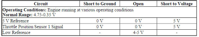
Throttle Position Sensor 2
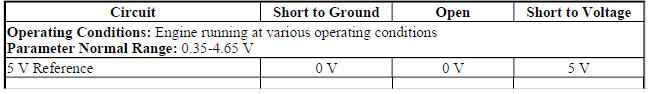

Circuit/System Description
The throttle body assembly contains 2 throttle position sensors. The throttle position sensors are mounted to the throttle body assembly and are not serviceable. The throttle position sensors provide a signal voltage that changes relative to throttle blade angle. The engine control module (ECM) supplies the throttle position sensors with a common 5 V reference circuit, a common low reference circuit, and two independent signal circuits.
The throttle position sensors have opposite functionality. throttle position sensor 1 signal voltage decreases and throttle position sensor 2 signal voltage increases as the accelerator pedal increases to wide open throttle (WOT).
Conditions for Running the DTC
P0122, P0123, P0222, and P0223
- DTC P06A3 is not set.
- The run/crank or powertrain relay voltage is greater than 6 V and reduced power is not active.
- The ignition is ON or the engine is operating.
- DTC P0122, P0123, P0222, P0223 run continuously when the above conditions are met.
P0121
- No Active or Pending DTCs.
- The engine speed is between 400-7,000 RPM.
- The engine coolant temperature (ECT) is between -7 to +125ºC (19-257ºF).
- The intake air temperature (IAT) is between -20 to +125ºC (-4 to +257ºF).
- DTC P0121 runs continuously when the above conditions are met.
P0121
- No Active or Pending DTCs.
- The engine speed is between 400-7,000 RPM.
- The engine coolant temperature (ECT) is between -7 to +125ºC (19-257ºF).
- The intake air temperature (IAT) is between -20 to +125ºC (-4 to +257ºF).
- DTC P0121 runs continuously when the above conditions are met.
P2135
- DTC P0122, P0123, P0222, P0223, or P06A3 is not set.
- The run/crank or powertrain relay voltage is greater than 6 V and reduced power is not active.
- The ignition is ON or the engine is operating.
- DTC P2135 runs continuously when the above conditions are met.
Conditions for Setting the DTC
P0121
The ECM detects the throttle position sensor is stuck within range for greater than 1 s.
P0122
The ECM detects the throttle position sensor 1 voltage is less than 0.325 V for greater than 1 s.
P0123
The ECM detects the throttle position sensor 1 voltage is greater than 4.75 V for greater than 1 s.
P0222
The ECM detects that the throttle position sensor 2 voltage is less than 0.25 V for greater than 1 s.
P0223
The ECM detects the throttle position sensor 2 voltage is greater than 4.59 V for greater than 1 s.
P2135
The ECM detects the difference between the throttle position sensor 1 and throttle position sensor 2 exceeds a predetermined value for greater than 1 s.
Action Taken When the DTC Sets
- DTC P0122, P0123, P0222, P0223, and P2135 are Type A DTCs.
- DTC P0121 is a Type B DTC.
- The ECM commands the TAC system to operate in the Reduced Engine Power mode.
- A message center or an indicator displays Reduced Engine Power.
- Under certain conditions the control module commands the engine OFF.
Conditions for Clearing the MIL/DTC
- DTCs P0122, P0123, P0222, P0223, and P2135 are Type A DTCs.
- DTC P0121 is a Type B DTC
Diagnostic Aids
- A high resistance condition on the throttle position and throttle actuator control circuits could cause a DTC to set.
- If the accelerator pedal is pressed to the wide open throttle position, the throttle blade angle or Throttle Position angle is limited to less than 40 percent.
Reference Information
Schematic Reference
Engine Controls Schematics (Encore) , Engine Controls Schematics (Encore)
Connector End View Reference
WIRING SYSTEMS AND POWER MANAGEMENT - COMPONENT CONNECTOR END VIEWS - INDEX - ENCORE WIRING SYSTEMS AND POWER MANAGEMENT - COMPONENT CONNECTOR END VIEWS - INDEX - Encore
Description and Operation
Throttle Actuator Control (TAC) System Description
Electrical Information Reference
- Circuit Testing
- Connector Repairs
- Testing for Intermittent Conditions and Poor Connections
- Wiring Repairs
DTC Type Reference
Powertrain Diagnostic Trouble Code (DTC) Type Definitions (LUV) , Powertrain Diagnostic Trouble Code (DTC) Type Definitions (2H0)
Scan Tool Reference
Control Module References for scan tool information
Circuit/System Verification
- Ignition ON.
- If you were sent here from DTC P0068, P0101, P0106, or P1101 refer to Circuit/System Testing.
- Verify that DTC P0641, P0651, P0697, or P06A3 is not set.
- If any of the DTCs are set
Refer to DTC P0641, P0651, P0697, or P06A3 (ECM) for further diagnosis.
- If none of the DTCs are set
- Verify the scan tool Throttle Body Idle Airflow Compensation parameter is less than 90 %.
- 90 % or greater
Refer to Throttle Body Inspection and Cleaning .
- If less than 90 %
- Verify the scan tool Throttle Position Sensor 1 and Throttle Position Sensor 2 voltage parameters are between 1.0-4.0 V and change with accelerator pedal input.
- If not between 1.0-4.0 V or does not change
Refer to Circuit/System Testing
- If between 1.0-4.0 V and changes
- Verify the scan tool Throttle Position Sensor 1 and 2 Agree/Disagree parameter displays Agree while performing the Throttle Sweep Test with a scan tool.
- If Disagree
Refer to Circuit/System Testing
- If Agree
- Determine the current vehicle testing altitude.
- Verify the scan tool MAP Sensor pressure parameter is within range specified in the Altitude Versus Barometric Pressure table.
- The MAP Sensor pressure is not in range
Refer to DTC P0106.
- The MAP Sensor pressure is within range
- Engine idling.
- Verify the scan tool MAP Sensor pressure parameter is between 26-52 kPa (3.8-7.5 psi) and changes with accelerator pedal input.
- If not between 26-52 kPa (3.8-7.5 psi) or does not change
Refer to DTC P0106.
- If between 26-52 kPa (3.8-7.5 psi) and changes
- Verify the scan tool MAF Sensor g/s parameter changes smoothly and gradually as the engine speed is increased and decreased while performing the actions listed below.
- Engine idling
- Perform the scan tool snapshot function.
- Increase the engine speed slowly to 3,000 RPM and then back to idle.
- Exit from the scan tool snapshot and review the data.
- Observe the MAF Sensor parameter frame by frame with a scan tool.
- The MAF Sensor parameter does not change smoothly and gradually
Refer to DTC P0101.
- The MAF Sensor parameter changes smoothly and gradually
- Verify the scan tool Boost Pressure Sensor pressure and BARO parameters are within 3 kPa (0.4 psi).
- The parameters are not within 3 kPa (0.4 psi)
Refer to DTC P0236
- The parameters are within 3 kPa (0.4 psi)
- Verify the scan tool MAP Sensor parameter and the Boost Pressure Sensor parameter are within 20 kPa (2.9 psi) during a WOT acceleration at the time of the 1-2 shift.
- The parameters are not within 20 kPa (2.9 psi)
Refer to DTC P0236.
- The parameters are within 20 kPa (2.9 psi)
- Operate the vehicle within the Conditions for Running the DTC. You may also operate the vehicle within the conditions that you observed from the Freeze Frame/Failure Records data.
- Verify the DTC does not set.
- If the DTC sets
Refer to Circuit/System Testing
- If the DTC does not set
- All OK
Circuit/System Testing
NOTE: Disconnecting the throttle body harness connector causes additional DTCs to set.
- Ignition OFF, and all vehicle systems OFF, disconnect the harness connector at Q38 Throttle Body. It may take up to 2 minutes for all vehicle systems to power down.
- Test for less than 5 ohms between the low reference circuit terminal C and ground.
- If 5 ohms or greater
- Ignition OFF, disconnect the harness connector at the K20 Engine Control Module.
- Test for less than 2 ohms in the low reference circuit end to end.
- If 2 ohms or greater, repair the open/high resistance in the circuit.
- If less than 2 ohms, replace the K20 Engine Control Module.
- If less than 5 ohms
- Ignition ON.
- Test for 4.8-5.2 V between the 5 V reference circuit terminal E and ground.
- If less than 4.8 V
- Ignition OFF, disconnect the harness connector at the K20 Engine Control Module.
- Test for infinite resistance between the 5 V reference circuit and ground
- If less than infinite resistance, repair the short to ground on the circuit.
- If infinite resistance
- Test for less than 2 ohms in the 5 V reference circuit end to end.
- If 2 ohms or greater, repair the open/high resistance in the circuit.
- If less than 2 ohms, replace the K20 Engine Control Module.
- If greater than 5.2 V
- Ignition OFF, disconnect the harness connector at the K20 Engine Control Module, ignition ON.
- Test for less than 1 V between the 5 V reference circuit and ground.
- If 1 V or greater, repair the short to voltage on the circuit.
- If less than 1 V, replace the K20 Engine Control Module.
- If between 4.8-5.2 V
- Ignition ON.
- Test for less than 1 V between the throttle position sensor 1 signal circuit terminal D and ground.
- If 1.0 V or greater
- Ignition OFF, disconnect the harness connector at the K20 Engine Control Module, ignition ON.
- Test for less than 1 V between the signal circuit and ground.
- If 1 V or greater, repair the short to voltage on the circuit.
- If less than 1 V, replace the K20 Engine Control Module.
- If 1.0 V or less
- Install a 3 A fused jumper wire between throttle position sensor 1 signal circuit terminal D and the 5 V reference circuit terminal E.
- Verify the scan tool throttle position sensor 1 voltage parameter is greater than 4.8 V.
If 4.8 V or less
- Ignition OFF, disconnect the harness connector at the K20 Engine Control Module.
- Test for infinite resistance between the signal circuit and ground.
- If less than infinite resistance, repair the short to ground on the circuit.
- If infinite resistance
- Test for less than 2 ohms in the signal circuit end to end.
- If 2 ohms or greater, repair the open/high resistance in the circuit.
- If less than 2 ohms, replace the K20 Engine Control Module.
- If 4.8 or greater
- Test for 4.8-5.2 V between the throttle position sensor 2 signal circuit terminal F and ground.
- If less than 4.8 V
- Ignition OFF, disconnect the harness connector at the K20 Engine Control Module.
- Test for infinite resistance between the signal circuit and ground.
- If less than infinite resistance, repair the short to ground on the circuit.
- If infinite resistance
- Test for less than 2 ohms in the signal circuit end to end.
- If 2 ohms or greater, repair the open/high resistance in the circuit.
- If less than 2 ohms, replace the K20 Engine Control Module.
- If greater than 5.2 V
- Ignition OFF, disconnect the harness connector at the K20 Engine Control Module, ignition ON.
- Test for less than 1 V between the signal circuit and ground.
- If 1 V or greater, repair the short to voltage on the circuit.
- If less than 1 V, replace the K20 Engine Control Module.
- If between 4.8-5.2 V
- Test or replace the Q38 Throttle Body.
Repair Instructions
- Throttle Body Assembly Replacement
- Control Module References for engine control module replacement, programming, and setup
Repair Verification
- Install any components that have been removed or replaced during diagnosis.
- Perform any adjustments, programming or setup procedures that are required when a component is removed or replaced.
- Clear the DTCs with a scan tool.
- Ignition OFF and all vehicle systems OFF. It may take up to 2 minutes for all vehicle systems to power down.
- Ignition ON.
- Verify the Throttle Position Sensors 1 and 2 Agree/Disagree parameter displays Agree while performing the Throttle Sweep Test with a scan tool.
- If Disagree
Test or replace the Q38 Throttle Body assembly.
- If Agree
- If the repair was related to a DTC, duplicate the Conditions for Running the DTC and use the Freeze Frame/Failure Records, if applicable, in order to verify the DTC does not set.
- If DTC sets
Refer to Diagnostic Trouble Code (DTC) List - Vehicle for further diagnosis.
- If DTC does not set
- All OK
DTC P0128
Diagnostic Instructions
- Perform the Diagnostic System Check - Vehicle prior to using this diagnostic procedure.
- Review Strategy Based Diagnosis for an overview of the diagnostic approach.
- Diagnostic Procedure Instructions provides an overview of each diagnostic category.
DTC Descriptor
DTC P0128
Engine Coolant Temperature (ECT) Below Thermostat Regulating Temperature
Circuit/System Description
NOTE: The engine coolant temperature sensor is referred to as B34A Engine Coolant Temperature Sensor 1 in schematics and other areas.
The engine control module (ECM) monitors the temperature of the engine coolant for engine control and enabling criteria for some diagnostics. The amount of air flow into an engine is proportional to the amount of heat an engine generates. The ECM monitors the amount of air flow into the engine to calculate engine coolant temperature (ECT). The ECM uses the calculated temperature to determine if the engine has warmed up to the thermostat regulating temperature. If the ECT does not increase normally or does not reach the thermostat regulating temperature, diagnostics that use the ECT as enabling criteria, may not run when expected. If the ECT fails to reach the thermostat regulating temperature, before a predetermined amount of air flow enters the engine, the DTC sets.
Conditions for Running the DTC
- DTCs P00B3, P00B6, P0101, P0102, P0103, P0111, P0112, P0113, P0116, P0117 or P0118 are not set.
- Average Airflow is greater than 11 g/s.
- Thermostat Heater duty commanded cycle 10%.
- Engine not run time 30 min
- Engine run time between 22 s and 30 min
- The DTC runs once per ignition key cycle.
Conditions for Setting the DTC
The ECM detects that the actual engine coolant temperature is 26ºC (78.8ºF) colder than the commanded engine coolant temperature while the IAT is between 10-65ºC (50-149ºF)
or
The ECM detects that the actual engine coolant temperature is 46ºC (114.8ºF) colder than the commanded engine coolant temperature while the IAT is between -7ºC to +10ºC (-19.4 to+50ºF)
Action Taken When the DTC Sets
DTC P0128 is a Type B DTC
Conditions for Clearing the DTC
DTC P0128 is a Type B DTC.
Reference Information
Schematic Reference
Engine Controls Schematics (Encore) , Engine Controls Schematics (Encore)
Connector End View Reference
WIRING SYSTEMS AND POWER MANAGEMENT - COMPONENT CONNECTOR END VIEWS - INDEX - ENCORE WIRING SYSTEMS AND POWER MANAGEMENT - COMPONENT CONNECTOR END VIEWS - INDEX - Encore
Electrical Information Reference
- Circuit Testing
- Connector Repairs
- Testing for Intermittent Conditions and Poor Connections
- Wiring Repairs
DTC Type Reference
Powertrain Diagnostic Trouble Code (DTC) Type Definitions (LUV) , Powertrain Diagnostic Trouble Code (DTC) Type Definitions (2H0)
Scan Tool Reference
Control Module References for scan tool information
Circuit/System Verification
- Verify the cooling system is filled to the correct coolant level. Refer to Loss of Coolant , and Cooling System Draining and Filling .
- If the coolant level is not correct
Repair as necessary
- If the coolant level is correct
- Verify the DTC P00B7, P0116, P0117, P0118, P0597, P0598, or P0599 is not set.
- If a DTC is set
Refer to Diagnostic Trouble Code (DTC) List - Vehicle
- If a DTC is not set
- Engine running for 15 min with the A/C OFF, increase the engine speed to 3,000 RPM.
- Verify the scan tool ECT Sensor parameter is greater than 79ºC (174ºF) when commanding the Engine Coolant Thermostat Heater to 0%.
- If less than 79ºC (174ºF)
Replace the E41 Engine Coolant Thermostat Heater.
- If greater than 79ºC (174ºF)
- Operate the vehicle within the Conditions for Running the DTC. You may also operate the vehicle within the conditions that you observed from the Freeze Frame/Failure Records data.
- Verify the DTC does not set.
- If the DTC sets
Refer to Step 1.
- If the DTC does not set
- All OK.
Component Testing
- Ignition OFF, disconnect the B34 Engine Coolant Temperature Sensor harness connector at the sensor.
- Test for refer to Temperature Versus Resistance Temperature Versus Resistance between the signal circuit terminal 1 and the low reference terminal 2.
- If the temperature versus resistance are not within the specified ranges
Replace the B34 Engine Coolant Temperature Sensor.
- If the temperature versus resistance are within the specified ranges
- Test for infinite resistance between each terminal and the sensor housing
- If less than infinite resistance
Replace the B34 Engine Coolant Temperature Sensor.
- If infinite resistance
- All OK.
Repair Instructions
Perform the Diagnostic Repair Verification after completing the repair.
- Engine Coolant Temperature Sensor Replacement (Water Outlet) , Engine Coolant Temperature Sensor Replacement (Radiator)
- Engine Coolant Thermostat Housing Removal
- Control Module References for engine control module replacement, programming and setup.
DTC P0131, P0132, P0134, P0137, P0138, OR P0140 (LUV)
Diagnostic Instructions
- Perform the Diagnostic System Check - Vehicle prior to using this diagnostic procedure.
- Review Strategy Based Diagnosis for an overview of the diagnostic approach.
- Diagnostic Procedure Instructions provides an overview of each diagnostic category.
DTC Descriptors
DTC P0131
HO2S Circuit Low Voltage Sensor 1
DTC P0132
HO2S Circuit High Voltage Sensor 1
DTC P0134
HO2S Circuit Insufficient Activity Sensor 1
DTC P0137
HO2S Circuit Low Voltage Sensor 2
DTC P0138
HO2S Circuit High Voltage Sensor 2
DTC P0140
HO2S Circuit Insufficient Activity Sensor 2
Diagnostic Fault Information
HO2S 1 or 2
.jpg)
Typical Scan Tool Data
HO2S 1 or 2
.jpg)
Circuit/System Description
The heated oxygen sensors (HO2S) are used for fuel control and catalyst monitoring. Each HO2S compares the oxygen content of the surrounding air with the oxygen content of the exhaust stream. When the engine is started, the control module operates in an open loop mode, ignoring the HO2S signal voltage while calculating the air to fuel ratio. While the engine runs, the HO2S heats up and begins to generate a voltage within a range of 0-1 275 mV. Once sufficient HO2S voltage fluctuation is observed by the control module, closed loop is entered. The control module uses the HO2S voltage to determine the air to fuel ratio. An HO2S voltage that increases toward 1 000 mV indicates a rich fuel mixture. An HO2S voltage that decreases toward 0 mV indicates a lean fuel mixture.
The heating elements inside each HO2S heat the sensor to bring the sensor up to operating conditions faster.
This allows the system to enter closed loop earlier and the control module to calculate the air to fuel ratio sooner
Conditions for Running the DTC
DTC P0131 or P0137
- DTCs P0068, P0106, P0107, P0108, P0121, P0122, P0123, P0222, P0223, P0442, P0443, P0446, P0449, P0451, P0452, P0453, P0454, P0455, P0496, P1101, P1516, P2101, P2119, P2135 and P2176 are not set.
- The ignition voltage is between 10-32 V.
- The fuel level is greater than 10%.
- The mass air flow (MAF) is between 2-60 g/s.
- The fuel composition is less than 87% ethanol.
- The fuel system is in Closed Loop.
- The vehicle is not decelerating.
- The DTC P0131 runs continuously when the above conditions are met for greater than 3 s.
- The DTC P0137 runs continuously when the above conditions are met for greater than 5 s.
DTC P0132 or P0138
- DTCs P0068, P0101, P0102, P0103, P0106, P0107, P0108, P0121, P0122, P0123, P0222, P0223, P0442, P0443, P0446, P0449, P0451, P0452, P0453, P0454, P0455, P0496, P1101, P1516, P2101, P2119, P2135 and P2176 are not set.
- The ignition voltage is between 10-32 V.
- The fuel level is greater than 10%.
- The fuel composition is less than 87% ethanol.
- The fuel system is in Closed Loop.
- Engine run time is greater than 5 s.
- The vehicle is not decelerating.
- The DTC P0132 and P0138 run continuously when the above conditions are met for greater than 3 s.
DTC P0134 or P0140
- DTCs P0068, P0101, P0102, P0103, P0121, P0122, P0123, P0222, P0223, P1516, P2101, P2119, P2135 and P2176 are not set.
- The ignition voltage is between 10-32 V.
- HO2S heater warm up is finished.
- Engine run time is greater than 5 s.
- The engine has been operating for greater than 50 s.
- The fuel composition is less than 87% ethanol.
Conditions for Setting the DTC
P0131
The engine control module (ECM) detects that the heated oxygen sensor (HO2S) voltage is less than 20 mV for greater than 38 s.
P0137
The engine control module (ECM) detects that the heated oxygen sensor (HO2S) is shorted to ground for greater than 38 s.
P0132 or P0138
The ECM detects that the heated oxygen sensor (HO2S) voltage is greater than 1 050 mV for greater than 10 s.
P0134 or P0140
The ECM detects that the heated oxygen sensor (HO2S) voltage is greater than 1 700 mV for greater than 10 s.
Action Taken When the DTC Sets
DTCs P0131, P0132, P0134, P0137, P0138 and P0140 are Type B DTCs.
Conditions for Clearing the DTC
DTCs P0131, P0132, P0134, P0137, P0138 and P0140 are Type B DTCs.
Reference Information
Schematic Reference
Engine Controls Schematics (Encore) , Engine Controls Schematics (Encore)
Connector End View Reference
WIRING SYSTEMS AND POWER MANAGEMENT - COMPONENT CONNECTOR END VIEWS - INDEX - ENCORE WIRING SYSTEMS AND POWER MANAGEMENT - COMPONENT CONNECTOR END VIEWS - INDEX - Encore
Electrical Information Reference
- Circuit Testing
- Connector Repairs
- Testing for Intermittent Conditions and Poor Connections
- Wiring Repairs
DTC Type Reference
Powertrain Diagnostic Trouble Code (DTC) Type Definitions (LUV) , Powertrain Diagnostic Trouble Code (DTC) Type Definitions (2H0)
Scan Tool Reference
Control Module References for scan tool information
Circuit/System Verification
- Ignition ON
- Verify no HO2S heater DTCs are set.
- If a DTC is set
Refer to Diagnostic Trouble Code (DTC) List - Vehicle .
- If a DTC is not set
- Engine running.
- Verify the scan tool HO2S 1 or 2 parameters are between 50-1,050 mV.
- If not between 50-1,050 mV
Refer to Circuit/System Testing.
- If between 50-1,050 mV
- Operate the vehicle within the Conditions for Running the DTC. You may also operate the vehicle within the conditions that you observed from the Freeze Frame/Failure Records data.
- Verify the DTC does not set.
- If the DTC sets
Refer to Circuit/System Testing.
- If the DTC does not set
- All OK.
Circuit/System Testing
- Ignition OFF and all vehicle systems OFF, disconnect the appropriate B52 Heated Oxygen Sensor harness connector. It may take up to 2 minutes for all vehicle systems to power down. Ignition ON.
- Test for 1.7-3.0 V between the high signal circuit terminal 4 and ground.
- If less than 1.7 V
- Ignition OFF, disconnect the harness connector at the K20 Engine Control Module.
- Test for infinite resistance between the high signal circuit terminal 4 and ground.
- If less than infinite resistance, repair the short to ground on the circuit.
- If infinite resistance
- Test for less than 2 ohms in the high signal circuit end to end.
- If 2 ohms or greater, repair the open/high resistance in the circuit.
- If less than 2 ohms, replace the K20 Engine Control Module.
- If greater than 3 V
- Ignition OFF, disconnect the harness connector at the K20 Engine Control Module. Ignition ON.
- Test for less than 1 V between the high signal circuit terminal 4 and ground.
- If 1 V or greater, repair the short to voltage on the circuit.
- If less than 1 V, replace the K20 Engine Control Module.
- If between 1.7-3.0 V
- Verify the scan tool HO2S 1 or 2 parameter is between 1.7-3.0 V.
- If less than 1.7 V
- Ignition OFF, disconnect the harness connector at the K20 Engine Control Module. Ignition ON.
- Test for infinite resistance between the low signal circuit terminal 3 and ground.
- If less than infinite resistance, repair the short to ground on the circuit.
- If infinite resistance, replace the K20 Engine Control Module.
- If greater than 1.7 V
- Connect a 3 A fused jumper wire between the high signal circuit terminal 4 and the low signal circuit terminal 3.
NOTE: The low signal circuit is tied to a pull-up circuit within the engine control module. A voltage of 0.0-1.1 V on the low signal circuit is normal.
- Verify the scan tool HO2S 1 or 2 parameter displays 0.0 V.
- If greater than 0.0 V
- Ignition OFF, disconnect the harness connector at the K20 Engine Control Module. Ignition ON.
- Test for less than 2 ohms in the low signal circuit end to end.
- If 2 ohms or greater, repair the open/high resistance in the circuit.
- If less than 2 ohms
- Test for less than 1 V between the low signal circuit terminal 3 and ground.
- If 1 V or greater, repair the short to voltage on the circuit.
- If less than 1 V, replace the K20 Engine Control Module.
- If 0.0 V
- Verify none of the conditions listed below exist:
- Water intrusion in the B52 HO2S harness connector
- Low or high fuel system pressure-Refer to Fuel System Diagnosis (LUJ) , Fuel System Diagnosis (LUV) .
- Fuel that is contaminated-Refer to Alcohol/Contaminants-in-Fuel Diagnosis .
- Fuel saturation of the evaporative emission (EVAP) canister
- Exhaust leaks
- Engine vacuum leaks
- If any of the conditions exist
Repair as necessary
- If none of the conditions exist
- Test or replace the B52 Heated Oxygen Sensor.
Repair Instructions
Perform the Diagnostic Repair Verification after completing the diagnostic procedure.
- Heated Oxygen Sensor Replacement - Sensor 1
- Heated Oxygen Sensor Replacement - Sensor 2
- Perform the scan tool Heated Oxygen Sensor Resistance Learn Reset after replacing an HO2S.
- Control Module References for ECM replacement, programming and setup
DTC P0131, P0132, P0134, P0137, P0138, OR P0140 (LUJ)
Diagnostic Instructions
- Perform the Diagnostic System Check - Vehicle prior to using this diagnostic procedure.
- Review Strategy Based Diagnosis for an overview of the diagnostic approach.
- Diagnostic Procedure Instructions provide an overview of each diagnostic category.
DTC Descriptors
DTC P0131
HO2S Circuit Low Voltage Sensor 1
DTC P0132
HO2S Circuit High Voltage Sensor 1
DTC P0134
HO2S Circuit Insufficient Activity Sensor 1
DTC P0137
HO2S Circuit Low Voltage Sensor 2
DTC P0138
HO2S Circuit High Voltage Sensor 2
DTC P0140
HO2S Circuit Insufficient Activity Sensor 2
Diagnostic Fault Information
.jpg)
.jpg)
Typical Scan Tool Data
HO2S 1 or 2
.jpg)
Circuit/System Description
The heated oxygen sensors (HO2S) are used for fuel control and catalyst monitoring. Each HO2S compares the oxygen content of the surrounding air with the oxygen content of the exhaust stream. When the engine is started, the control module operates in an open loop mode, ignoring the HO2S signal voltage while calculating the air to fuel ratio. While the engine runs, the HO2S heats up and begins to generate a voltage within a range of 0-1 000 mV. Once sufficient HO2S voltage fluctuation is observed by the control module, closed loop is entered. The control module uses the HO2S voltage to determine the air to fuel ratio. An HO2S voltage that increases toward 1 000 mV indicates a rich fuel mixture. An HO2S voltage that decreases toward 0 mV indicates a lean fuel mixture.
The heating elements inside each HO2S heat the sensor to bring the sensor up to operating conditions faster.
This allows the system to enter closed loop earlier and the control module to calculate the air to fuel ratio sooner.
Conditions for Running the DTC
P0131, P0132, P0137, or P0138
- DTC P0030, P0036, P0106, P0107, P0108, P0112, P0113, P0117, P0118, P0121, P0122, P0123, P0201, P0202, P0203, P0204, P0443, or P2135 is not set.
- The engine is operating.
- The ignition voltage is between 10-32 V.
- The fuel system is in closed loop.
- The vehicle is not decelerating.
- The DTC runs continuously when the above conditions are met for 5 s.
P0134
- The ECM detects that the heated oxygen sensor (HO2S) 1 parameter is between 400-500 mV for 100 s.
- The throttle position indicated angle parameter changes more than 1%, 3 times.
- DTC P0134 sets within 100 s when the above condition is met.
P0140
- The ECM detects that the heated oxygen sensor (HO2S) 2 parameter is between 425-475 mV.
- The throttle position indicated angle parameter changes more than 1%, 3 times.
- DTC P0140 sets within 100 s when the above conditions are met.
Conditions for Setting the DTC
P0131
The engine control module (ECM) detects that the heated Oxygen Sensor (HO2S) voltage is less than 20 mV for greater than 38 s.
P0132 and P0138
The ECM detects that the heated Oxygen Sensor (HO2S) voltage is greater than 1 050 mV for greater than 10 s.
P0134
- The ECM detects that the heated oxygen sensor (HO2S) 1 parameter is between 400-500 mV for 100 s.
- The throttle position indicated angle parameter changes more than 1%, 3 times.
- DTC P0134 sets within 100 s when the above conditions are met.
P0137
The engine control module (ECM) detects that the heated Oxygen Sensor (HO2S) voltage is less than 20 mV for greater than 43 s.
P0140
- The ECM detects that the heated oxygen sensor (HO2S) 2 parameter is between 425-475 mV.
- The throttle position indicated angle parameter changes more than 1%, 3 times.
- DTC P0140 sets within 100 s when the above conditions are met.
Action Taken When the DTC Sets
DTC P0131, P0132, P0134, P0137, P0138, and P0140 are Type B DTCs
Conditions for Clearing the DTC
DTC P0131, P0132, P0134, P0137, P0138, and P0140 are Type B DTCs.
Reference Information
Schematic Reference
Engine Controls Schematics (Encore) , Engine Controls Schematics (Encore)
Connector End View Reference
WIRING SYSTEMS AND POWER MANAGEMENT - COMPONENT CONNECTOR END VIEWS - INDEX - ENCORE WIRING SYSTEMS AND POWER MANAGEMENT - COMPONENT CONNECTOR END VIEWS - INDEX - Encore
Electrical Information Reference
- Circuit Testing
- Connector Repairs
- Testing for Intermittent Conditions and Poor Connections
- Wiring Repairs
DTC Type Reference
Powertrain Diagnostic Trouble Code (DTC) Type Definitions (LUV) , Powertrain Diagnostic Trouble Code (DTC) Type Definitions (2H0)
Scan Tool Reference
Control Module References for scan tool information
Circuit/System Verification
- Ignition ON.
- Verify no HO2S heater DTCs are set.
- If a DTC is set.
Refer to Diagnostic Trouble Code (DTC) List - Vehicle .
- If a DTC is not set.
- Engine running.
- Verify the scan tool HO2S Sensor 1 or 2 parameters are between 50-1,050 mV.
- If not between 50-1,050 mV.
Refer to Circuit/System Testing.
- If between 50-1,050 mV.
- Operate the vehicle within the conditions for running the DTC. You may also operate the vehicle within the conditions that you observed from the Freeze Frame/Failure Records data.
- Verify the DTC does not set.
- If the DTC sets.
Refer to Circuit/System Testing.
- If the DTC does not set.
- All OK.
Circuit/System Testing
- Ignition OFF and all vehicle systems OFF, disconnect the appropriate B52 Heated Oxygen Sensor harness connector. It may take up to 2 minutes for all vehicle systems to power down. Ignition ON.
- Test for 1.7-3.0 V between the high signal circuit terminal 4 and ground.
- If less than 1.7 V.
- Ignition OFF, disconnect the harness connector at the K20 Engine Control Module.
- Test for the infinite resistance between the high signal circuit terminal 4 and ground.
- If less than infinite resistance, repair the short to ground on the circuit.
- If infinite resistance
- Test for less than 2 ohms in the high signal circuit end to end.
- If 2 ohms or greater, repair the open/high resistance in the circuit.
- If less than 2 ohms, replace the K20 Engine Control Module.
- If greater than 3 V
- Ignition OFF, disconnect the harness connector at the K20 Engine Control Module, ignition ON.
- Test for less than 1 V between the high signal circuit terminal 4 and ground.
- If 1 V or greater, repair the short to voltage on the circuit.
- If less than 1 V, replace the K20 Engine Control Module.
- If between 1.7-3.0 V
- Verify the scan tool heated oxygen sensor 1 or 2 parameter is between 1.7-3.0 V.
- If less than 1.7 V
- Ignition OFF, disconnect the harness connector at the K20 Engine Control Module, ignition ON.
- Test for infinite resistance between the low signal circuit terminal 3 and ground.
- If less than infinite resistance, repair the short to ground on the circuit.
- If infinite resistance, replace the K20 Engine Control Module.
- If greater than 1.7 V
- Connect a 3 A fused jumper wire between the high signal circuit terminal 4 and the low signal circuit terminal 3.
NOTE: The low signal circuit is tied to a pull-up circuit within the engine control module. A voltage of 0.0-1.1 V on the low signal circuit is normal.
- Verify the scan tool heated oxygen sensor 1 or 2 voltage parameter displays 0.0 V.
- If greater than 0.0 V
- Ignition OFF, disconnect the harness connector at the K20 Engine Control Module, ignition ON.
- Test for less than 2 ohms in the low signal circuit end to end.
- If 2 ohms or greater, repair the open/high resistance in the circuit.
- If less than 2 ohms
- Test for less than 1 V between the low signal circuit terminal 3 and ground.
- If 1 V or greater, repair the short to voltage on the circuit.
- If less than 1 V, replace the K20 Engine Control Module.
- If 0.0 V
- Verify none of the conditions listed below exist:
- Water intrusion in the B52 Heated Oxygen Sensor harness connector
- Low or high fuel system pressure-Refer to Fuel System Diagnosis (LUJ) , Fuel System Diagnosis (LUV) .
- Fuel that is contaminated-Refer to Alcohol/Contaminants-in-Fuel Diagnosis .
- Fuel saturation of the evaporative emission (EVAP) canister
- Exhaust leaks
- Engine vacuum leaks
- If any of the conditions exist
Repair as necessary.
- If none of the conditions exist
- Test or replace the B52 Heated Oxygen Sensor.
Repair Instructions
Perform the Diagnostic Repair Verification after completing the diagnostic procedure.
- Heated Oxygen Sensor Replacement - Sensor 1
- Heated Oxygen Sensor Replacement - Sensor 2
- Perform the scan tool Heated Oxygen Sensor Resistance learn Reset after replacing a heated oxygen sensor.
- Control Module References for ECM replacement, programming and setup
DTC P0133, P013A, P013B, P013E, P013F, P015A, P015B, P2270, OR P2271 (LUV)
Diagnostic Instructions
- Perform the Diagnostic System Check - Vehicle prior to using this diagnostic procedure.
- Review Strategy Based Diagnosis for an overview of the diagnostic approach.
- Diagnostic Procedure Instructions provide an overview of each diagnostic category.
DTC Descriptors
DTC P0133
HO2S Slow Response Sensor 1
DTC P013A
HO2S Slow Response Rich to Lean Sensor 2
DTC P013B
HO2S Slow Response Lean to Rich Sensor 2
DTC P013E
HO2S Delayed Response Rich to Lean Sensor 2
DTC P013F
HO2S Delayed Response Lean to Rich Sensor 2
DTC P015A
HO2S Delayed Response Rich to Lean Sensor 1
DTC P015B
HO2S Delayed Response Lean to Rich Sensor 1
DTC P2270
HO2S Signal Stuck Lean Sensor 2
DTC P2271
HO2S Signal Stuck Rich Sensor 2
Diagnostic Fault Information
.jpg)
.jpg)
Typical Scan Tool Data
HO2S 1 or 2
.jpg)
Circuit/System Description
The heated oxygen sensors (HO2S) are used for fuel control and catalyst monitoring. Each HO2S compares the oxygen content of the surrounding air with the oxygen content of the exhaust stream. When the engine is started, the control module operates in an open loop mode, ignoring the HO2S signal voltage while calculating the air to fuel ratio. While the engine runs, the HO2S heats up and begins to generate a voltage within a range of 0-1 275 mV. Once sufficient HO2S voltage fluctuation is observed by the control module, closed loop is entered. The control module uses the HO2S voltage to determine the air to fuel ratio. An HO2S voltage that increases toward 1 000 mV indicates a rich fuel mixture. An HO2S voltage that decreases toward 0 mV indicates a lean fuel mixture.
The heating elements inside each HO2S heat the sensor to bring the sensor up to operating conditions faster.
This allows the system to enter closed loop earlier and the control module to calculate the air to fuel ratio sooner.
Conditions for Running the DTC
DTC P0133
- DTCs P0068, P0096, P0097, P0098, P00B3, P00B4, P00B6, P00C7, P0101, P0102, P0103, P0106, P0107, P0108, P0111, P0112, P0113, P0114, P0116, P0117, P0118, P0119, P0121, P0122, P0123, P0128, P0131, P0132, P0134, P0201, P0202, P0203, P0204, P0222, P0223, P0300, P0442, P0443, P0446, P0449, P0451, P0452, P0453, P0454, P0455, P0496, P1101, P1516, P2101, P2119, P2135, P2176 and P2450 are not set.
- The ignition voltage is between 10-32 V.
- The engine speed parameter is between 1 300-3 500 RPM.
- The engine coolant temperature (ECT) is hotter than 65ºC (149ºF).
- The intake air temperature (IAT) is hotter than -40ºC (-40ºF).
- The engine has been operating for greater than 100 s.
- The mass air flow (MAF) is between 10-35 g/s.
- The fuel system is in Closed Loop.
- The vehicle is not decelerating.
- The DTCs run continuously when the above conditions are met for greater than 1 s.
P013A
- DTCs P0068, P0096, P0097, P0098, P00B6, P0101, P0102, P0103, P0106, P0107, P0108, P0111, P0112, P0113, P0114, P0116, P0117, P0118, P0119, P0121, P0122, P0123, P0171, P0172, P0201, P0202, P0203, P0204, P0222, P0223, P0300, P1101, P1516, P2096, P2097, P2101, P2119, P2135, P2176 are not set.
- The ignition voltage is between 10-32 V.
- The fuel level is greater than 10%.
- DTC P013B, P013E, P013F, P2270 and P2271 have run.
- DTC P013E and P2270 have passed.
- DTC P013A runs once per trip.
P013B
- DTCs P0068, P0096, P0097, P0098, P00B6, P0101, P0102, P0103, P0106, P0107, P0108, P0111, P0112, P0113, P0114, P0116, P0117, P0118, P0119, P0121, P0122, P0123, P0171, P0172, P0201, P0202, P0203, P0204, P0222, P0223, P0300, P1101, P1516, P2096, P2097, P2101, P2119, P2135, P2176 are not set.
- The ignition voltage is between 10-32 V.
- The fuel level is greater than 10%.
- DTC P013A, P013E, P013F, P2270 and P2271 have run.
- DTC P013F and P2271 have passed.
- DTC P013B runs once per trip.
P013E
- DTCs P0068, P0096, P0097, P0098, P00B6, P0101, P0102, P0103, P0106, P0107, P0108, P0111, P0112, P0113, P0114, P0116, P0117, P0118, P0119, P0121, P0122, P0123, P0171, P0172, P0201, P0202, P0203, P0204, P0222, P0223, P0300, P1101, P1516, P2096, P2097, P2101, P2119, P2135, P2176 are not set.
- The ignition voltage is between 10-32 V.
- The fuel level is greater than 10%.
- DTC P013A, P013B, P013F, P2270 and P2271 have run.
- DTC P2270 have passed.
- DTC P013E runs once per trip.
P013F
- DTCs P0068, P0096, P0097, P0098, P00B6, P0101, P0102, P0103, P0106, P0107, P0108, P0111, P0112, P0113, P0114, P0116, P0117, P0118, P0119, P0121, P0122, P0123, P0171, P0172, P0201, P0202, P0203, P0204, P0222, P0223, P0300, P1101, P1516, P2096, P2097, P2101, P2119, P2135, P2176 are not set.
- The ignition voltage is between 10-32 V.
- The fuel level is greater than 10%.
- DTC P013A, P013B, P013E, P2270 and P2271 have run.
- DTC P2270 and P2271 have passed.
- DTC P013F runs once per trip.
P015A and P015B
- DTCs P0068, P0101, P0102, P0103, P0106, P0107, P0108, P0111, P0112, P0113, P0114, P0116, P0117, P0118, P0119, P0121, P0122, P0123, P0128, P0131, P0132, P0134, P0171, P0172, P0201, P0202, P0203, P0204, P0222, P0223, P0300, P0442, P0443, P0446, P0449, P0452, P0453, P0455, P0496, P16F3, P2101 or P2135 are not set.
- The ignition voltage is between 10-32 V.
- The device controls are not active.
- The fuel level is greater than 10%.
- The HO2S heater is commanded ON for greater than 40 s.
- The engine coolant temperature (ECT) is hotter than 60ºC (140ºF).
- The intake air temperature (IAT) is hotter than -40ºC (-40ºF).
- The engine has been operating for greater than 150 s.
- The engine speed is between 1 550-3 500 RPM to initially enable the test.
- The vehicle speed is between 70-125 km/h (44-78 mph) to initially enable the test.
- The engine speed is between 1 350-3 650 RPM to keep the test enabled.
- The vehicle speed is between 65-130 km/h (41-81 mph) to keep the test enabled.
- The mass air flow (MAF) is between 2-20 g/s.
- The fuel system is in Closed Loop.
- The evaporative emission (EVAP) diagnostics are not in control of purge.
- The predicted catalytic converter temperature is between 550-900ºC (1 022-1 652ºF).
- DTC P015A runs once per trip, during the deceleration fuel cut-off (DFCO) mode, when the above conditions are met.
- DTC P015B runs once per trip, during the fuel enrich mode, when the above conditions are met.
P2270
- DTCs P0068, P0096, P0097, P0098, P00B6, P0101, P0102, P0103, P0106, P0107, P0108, P0111, P0112, P0113, P0114, P0116, P0117, P0118, P0119, P0121, P0122, P0123, P0171, P0172, P0201, P0202, P0203, P0204, P0222, P0223, P0300, P1101, P1516, P2096, P2097, P2101, P2119, P2135, P2176 are not set.
- The ignition voltage is between 10-32 V.
- The fuel level is greater than 10%.
- The engine speed parameter is between 1 100-3 500 RPM.
- The mass air flow (MAF) is between 1-30 g/s.
- The fuel composition is less than 87% ethanol.
- The fuel system is in Closed Loop.
- DTC P013A, P013B, P013E, P013F, P2270 and P2271 have run.
- DTC P2270 and P2271 have passed.
- DTC P2270 runs once per drive cycle when the above conditions are met for 5 s.
P2271
- DTCs P0068, P0096, P0097, P0098, P00B6, P0101, P0102, P0103, P0106, P0107, P0108, P0111, P0112, P0113, P0114, P0116, P0117, P0118, P0119, P0121, P0122, P0123, P0171, P0172, P0201, P0202, P0203, P0204, P0222, P0223, P0300, P1101, P1516, P2096, P2097, P2101, P2119, P2135, P2176 are not set.
- The ignition voltage is between 10-32 V.
- The fuel level is greater than 10%.
- The engine speed parameter is between 1 100-3 500 RPM.
- The mass air flow (MAF) is between 1-30 g/s.
- The fuel composition is less than 87% ethanol.
- The fuel system is in Closed Loop.
- DTC P013A, P013B, P013E, P013F and P2270 have run.
- DTC P013A, P013E and P2270 have passed.
- DTC P2270 runs once per drive cycle when the above conditions are met for 5 s.
Conditions for Setting the DTC
P0133
- The ECM detects that the HO2S 1 average response time is more than a calculated value.
- DTC P0133 sets within 60 s when the above condition is met.
P013A
The ECM detects that the accumulated mass air flow monitored during rich to lean transitions between 150-450 mV is more than 6 g.
P013B
The ECM detects that the accumulated mass air flow monitored during rich to lean transitions between 335-650 mV is more than 25 g.
P013E
The ECM detects that the Post O2 sensor voltage is greater than 450 mV and the accumulated mass air flow monitored during the delayed Response Test is greater than 20 g.
P013F
The ECM detects that the Post O2 sensor voltage is less than 350 mV and the accumulated mass air flow monitored during the delayed Response Test is greater than 70 g.
P0140
The ECM detects that the heated oxygen sensor (HO2S) 2 parameter is greater than 1 700 mV.
P2270
- The ECM detects that the heated oxygen sensor (HO2S) 2 sensor cannot achieve voltage equal to or less than 775 mV.
and
- The ECM detects that the accumulated mass air flow monitored during the Stuck Lean Voltage Test is more than 38 g.
P2271
- The ECM detects that the heated oxygen sensor (HO2S) 2 sensor cannot achieve voltage equal to or less than 100 mV.
and
- The ECM detects that the accumulated mass air flow monitored during the stuck rich voltage test is more than 25 g.
Action Taken When the DTC Sets
- DTCs P0133, P0134, P013E, P013F, P0140, P2270 are P2271 Type B DTCs.
- DTCs P013A and P013B are Type A DTCs.
Conditions for Clearing the DTC
- DTCs P0133, P0134, P013E, P013F, P0140, P2270 are P2271 Type B DTCs.
- DTCs P013A and P013B are Type A DTCs.
Reference Information
Schematic Reference
- Engine Controls Schematics (Encore) , Engine Controls Schematics (Encore)
Connector End View Reference
WIRING SYSTEMS AND POWER MANAGEMENT - COMPONENT CONNECTOR END VIEWS - INDEX - ENCORE WIRING SYSTEMS AND POWER MANAGEMENT - COMPONENT CONNECTOR END VIEWS - INDEX - Encore
Electrical Information Reference
- Circuit Testing
- Connector Repairs
- Testing for Intermittent Conditions and Poor Connections
- Wiring Repairs
DTC Type Reference
Powertrain Diagnostic Trouble Code (DTC) Type Definitions (LUV) , Powertrain Diagnostic Trouble Code (DTC) Type Definitions (2H0)
Scan Tool Reference
Control Module References for scan tool information
Circuit/System Verification
- Ignition ON.
- Verify no HO2S heater DTCs are set
- If a HO2S heater DTC is set
Refer to DTC P0131, P0132, P0134, P0137, P0138, or P0140 (LUV), DTC P0131, P0132, P0134, P0137, P0138, or P0140 (LUJ).
- If no HO2S heater DTC is set
- Allow the engine to reach operating temperature, engine running.
- Verify the scan tool HO2S Sensor 1 or 2 voltage parameters are between 50-1 050 mV.
- If not between 50-1 050 mV
Refer to DTC P0131, P0132, P0134, P0137, P0138, or P0140 (LUV), DTC P0131, P0132, P0134, P0137, P0138, or P0140 (LUJ).
- If between 50-1 050 mV
- Verify none of the following conditions exist:
- Lean or rich fuel injectors
- Water intrusion in the HO2S harness connector
- Low or high fuel system pressure-Refer to Fuel System Diagnosis (LUJ) , Fuel System Diagnosis (LUV) .
- Fuel that is contaminated-Refer to Alcohol/Contaminants-in-Fuel Diagnosis .
- Fuel saturation of the evaporative emission (EVAP) canister
- Exhaust leaks
- Engine vacuum leaks
- Engine oil consumptions-Refer to Symptoms - Engine Cooling .
- Engine coolant consumption-Refer to Symptoms - Engine Cooling .
- If any of the above conditions exist
Repair as necessary.
- If none of the above conditions exist
- Operate the vehicle within the Conditions for Running the DTC. You may also operate the vehicle within the conditions that you observed from the Freeze Frame/Failure Records data.
- Verify the DTC does not set.
- If the DTC sets
Replace the B52 Heated Oxygen Sensor.
- If the DTC does not set
- All OK.
Repair Instructions
Perform the Diagnostic Repair Verification after completing the diagnostic procedure.
- Heated Oxygen Sensor Replacement - Sensor 1
- Heated Oxygen Sensor Replacement - Sensor 2
- Perform the scan tool Heated Oxygen Sensor Resistance Learn Reset after replacing a HO2S.
- Control Module References for ECM replacement, programming and setup
DTC P0133, P1133, P2270, OR P2271 (LUJ)
Diagnostic Instructions
- Perform the Diagnostic System Check - Vehicle prior to using this diagnostic procedure.
- Review Strategy Based Diagnosis for an overview of the diagnostic approach.
- Diagnostic Procedure Instructions provide an overview of each diagnostic category.
DTC Descriptors
DTC P0133
HO2S Slow Response Sensor 1
DTC P1133
HO2S Insufficient Switching Sensor 1
DTC P2270
HO2S Signal Stuck Lean Sensor 2
DTC P2271
HO2S Signal Stuck Rich Sensor 2
Diagnostic Fault Information
.jpg)
Typical Scan Tool Data
HO2S 1 or 2
.jpg)
Circuit/System Description
The heated oxygen sensors (HO2S) are used for fuel control and catalyst monitoring. Each HO2S compares the oxygen content of the surrounding air with the oxygen content of the exhaust stream. When the engine is started, the control module operates in an open loop mode, ignoring the HO2S signal voltage while calculating the air to fuel ratio. While the engine runs, the HO2S heats up and begins to generate a voltage within a range of 0-1 000 mV. Once sufficient HO2S voltage fluctuation is observed by the control module, closed loop is entered. The control module uses the HO2S voltage to determine the air to fuel ratio. An HO2S voltage that increases toward 1 000 mV indicates a rich fuel mixture. An HO2S voltage that decreases toward 0 mV indicates a lean fuel mixture.
The heating elements inside each HO2S heat the sensor to bring the sensor up to operating conditions faster.
This allows the system to enter closed loop earlier and the control module to calculate the air to fuel ratio sooner.
Conditions for Running the DTC
P0133
- DTC P0068, P0101, P0102, P0103, P0106, P0107, P0108, P0112, P0113, P0117, P0118, P0120, P0121, P0122, P0123, P0201, P0202, P0203, P0204, P0220, P0222, P0223, P0443, P1516, P2101, P2119, P2135 or P2176 is not set.
- The engine coolant temperature (ECT) sensor parameter is more than 70ºC (158ºF).
- The ignition signal parameter is between 10-18 V.
- The fuel level sensor parameter is more than 10%.
- The engine run time parameter is more than 200 s.
- The engine speed parameter is between 1 000-3 500 RPM.
- The manifold absolute pressure (MAP) sensor parameter is more than 30 kPa.
- The mass air flow (MAF) sensor parameter is between 11-50 g/s.
- The loop status parameter is closed.
- The throttle position indicated angle parameter is more than 5%.
- DTC P0131 runs once per drive cycle when the above conditions are met for 2 s.
P1133
- DTC P0068, P0101, P0102, P010, P0106, P0107, P0108, P0112, P0113, P0117, P0118, P0120, P0121, P0122, P0123, P0201, P0202, P0203, P0204, P0220, P0222, P0223, P0443, P1516, P2101, P2119, P2135 or P2176 is not set.
- The ECT sensor parameter is more than 70ºC (158ºF).
- The engine speed parameter is between 1 500-3 500 RPM.
- The system voltage is between 10-18 V.
- The engine run time parameter is more than 200 s.
- The loop status parameter is closed.
- The throttle position indicated angle parameter is more than 5.
- The fuel level sensor parameter is more than 10%.
- The MAP sensor parameter is more than 30 kPa.
- The MAF sensor parameter is between 11-50 g/s.
- The engine coolant is hotter than 50.25ºC (122.45ºF).
- DTC P1133 runs once per drive cycle when the above conditions are met for 2 s.
P2270
- DTC P0030, P0036, P0053, P0054, P0101, P0102, P0103, P0106, P0107, P0108, P0120, P0121, P0122, P0123, P0131, P0132, P0133, P0134, P0135, P0137, P0138, P013A, P013B, P013E, P013F, P0140, P0141, P0171, P0172, P0201, P0202, P0203, P0204, P0220, P0222, P0223, P0300, P0443, P1133, P1516, P2101, P2119, P2135, P2176 or P2271 is not set.
- The system voltage is between 10-18 V.
- The fuel level is more than 10%.
- Engine run time is equal to or more than 255 s.
Then
- The engine speed is between 1 100-3 200 RPM.
- The airflow is equal to or more than 0 g/s and equal to or less than 25 g/s.
- The vehicle speed is equal to or more than 45 km/h (28 MPH) and equal to or less than 129 km/h (80 MPH).
- The short term fuel trim is equal to or more than 0.9, and equal to or less than 1 065.
- The loop status parameter is closed.
- The evaporative emission (EVAP) diagnostics are not in control of purge.
- The heater warm-up delay is more than 120 s.
- The catalyst temperature is equal to or more than 650ºC (1 202ºF), and equal to less than 900ºC (1 652º F).
- DTC P2270 runs once per trip when the above conditions have been met for 2 s.
P2271
- DTC P0030, P0036, P0053, P0054, P0101, P0102, P0103, P0106, P0107, P0108, P0120, P0121, P0122, P0123, P0131, P0132, P0133, P0134, P0135, P0137, P0138, P013A, P013B, P013E, P013F, P0140, P0141, P0171, P0172, P0201, P0202, P0203, P0204, P0220, P0222, P0223, P0300, P0443, P1133, P1516, P2101, P2119, P2135, P2176 or P2270 is not set.
- The system voltage is between 10-18 V.
- The fuel level is more than 10%.
- Engine run time is equal to or more than 255 s.
Then
- Deceleration fuel cut-off is active.
- The accelerator pedal position (APP) is stable.
- The torque converter clutch (TCC) is locked.
- DTC P013A, P013E, and P2270 have run and passed.
- DTC P2271 runs once per trip.
Conditions for Setting the DTC
P0133
- The ECM detects that the heated oxygen sensor (HO2S) 1 rich to lean or lean to rich average response time is more than 0.1 s.
- DTC P0133 sets within 60 s when the above condition is met.
P1133
- The ECM detects that the heated oxygen sensor (HO2S) 1 rich to lean counts, or the lean to rich counts are less than a calibrated value.
- DTC P1133 sets within 60 s when the above condition is met.
P2270
- The ECM detects that the heated oxygen sensor (HO2S) 2 sensor cannot achieve voltage equal to or more than 775 mV.
and
- The ECM detects that the accumulated mass air flow monitored during the Stuck Lean Voltage Test is more than 45 g.
P2271
- The ECM detects that the heated oxygen sensor (HO2S) 2 sensor cannot achieve voltage equal to or less than 100 mV.
and
- The ECM detects that the accumulated mass air flow monitored during the stuck rich voltage test is more than 20 g.
Action Taken When the DTC Sets
DTC P0133, P1133, P2270 and P2271 are Type B DTCs.
Conditions for Clearing the DTC
DTC P0133, P1133, P2270 and P2271 are Type B DTCs.
Reference Information
Schematic Reference
Engine Controls Schematics (Encore) , Engine Controls Schematics (Encore)
Connector End View Reference
WIRING SYSTEMS AND POWER MANAGEMENT - COMPONENT CONNECTOR END VIEWS - INDEX - ENCORE WIRING SYSTEMS AND POWER MANAGEMENT - COMPONENT CONNECTOR END VIEWS - INDEX - Encore
Electrical Information Reference
- Circuit Testing
- Connector Repairs
- Testing for Intermittent Conditions and Poor Connections
- Wiring Repairs
DTC Type Reference
Powertrain Diagnostic Trouble Code (DTC) Type Definitions (LUV) , Powertrain Diagnostic Trouble Code (DTC) Type Definitions (2H0)
Scan Tool Reference
Control Module References for scan tool information
Circuit/System Verification
- Ignition ON.
- Verify no HO2S heater DTCs are set.
- If a DTC is set
Refer to Diagnostic Trouble Code (DTC) List - Vehicle .
- If a DTC is not set
- Verify none of the following conditions exist:
- Lean or rich fuel injectors-Refer to Fuel Injector Diagnosis
- Water intrusion in the HO2S harness connector
- Low or high fuel system pressure, refer to Fuel System Diagnosis (LUJ) , Fuel System Diagnosis (LUV) .
- Fuel that is contaminated, refer to Alcohol/Contaminants-in-Fuel Diagnosis .
- Fuel saturation of the evaporative emission (EVAP) canister
- Exhaust leaks
- Engine vacuum leaks
- Engine oil consumption-Refer to Oil Consumption Diagnosis
- Engine coolant consumption-Refer to Loss of Coolant
- If any of the conditions exist
Repair as necessary.
- If any of the conditions exist
- Operate the vehicle within the Conditions for Running the DTC. You may also operate the vehicle within the conditions that you observed from the Freeze Frame/Failure Records data.
- Verify the DTC does not set.
- If the DTC sets
Test or replace the appropriate B52 HO2S.
- If the DTC does not set
- All OK.
Repair Instructions
Perform the Diagnostic Repair Verification after completing the repair.
- Heated Oxygen Sensor Replacement - Sensor 1
- Heated Oxygen Sensor Replacement - Sensor 2
- Perform the scan tool Heated Oxygen Sensor Resistance Learn Reset after replacing a heated oxygen sensor.
- Control Module References for ECM replacement, programming and setup
DTC P0171 OR P0172
Diagnostic Instructions
- Perform the Diagnostic System Check - Vehicle prior to using this diagnostic procedure.
- Review Strategy Based Diagnosis for an overview of the diagnostic approach.
- Diagnostic Procedure Instructions provides an overview of each diagnostic category.
DTC Descriptors
DTC P0171
Fuel Trim System Lean
DTC P0172
Fuel Trim System Rich
Circuit/System Description
The engine control module (ECM) controls a Closed Loop air/fuel metering system in order to provide the best possible combination of driveability, fuel economy, and emission control. The ECM monitors the heated oxygen sensor (HO2S) signal voltage, and adjusts the fuel delivery based on the signal voltage while in Closed Loop. A change made to the fuel delivery changes the long and short term fuel trim values. The short term fuel trim values change rapidly in response to the HO2S signal voltages. These changes fine tune the engine fueling.
The long term fuel trim values change in response to trends in the short term fuel trim The long term fuel trim makes coarse adjustments to fueling in order to re-center and restore control to short term fuel trim. The ideal fuel trim values are around 0 %. A positive fuel trim value indicates that the ECM is adding fuel in order to compensate for a lean condition. A negative fuel trim value indicates that the ECM is reducing the amount of fuel in order to compensate for a rich condition
Conditions for Running the DTC
- DTCs P0030, P0053, P0101, P0102, P0103, P0106, P0107, P0108, P0131-P0135, P0178, P0179, P0201- P0204, P0261, P0262, P0264, P0265, P0267, P0268, P0270, P0271, P0300-P0304, P0411, P0442, P0455, P0458, P0496, P0506, P0507, P1248, P1249, P124A, P124B, P2147, P2148, P2150, P2151, P2153, P2154, P2156, P2157, P2227, P2228, P2229, P2230, P2269, P2440, or P2444 are not set.
- The engine is in Closed Loop status.
- The catalyst monitor diagnostic intrusive test, post 02 diagnostic intrusive test, and evaporative emissions system leak test are not active.
- The engine coolant temperature (ECT) is between -20ºC and +130ºC (-4ºF and +266ºF).
- The intake air temperature (IAT) is between -20ºC and +150ºC (-4ºF and +302ºF).
- The manifold absolute pressure (MAP) is between 18-253 kPa (2.6-36.7 psi).
- The engine speed is between 400-6,100 RPM.
- The mass air flow (MAF) is between 1.5-505 g/s.
- The barometric pressure (BARO) is greater than 70 kPa (10.2 psi).
- The fuel level is greater than 10 % and no fuel sensor fault is present.
- This diagnostic runs continuously when the above conditions have been met.
Conditions for Setting the DTC
- The average long term fuel trim weighted average value is greater or less than a calibrated value.
- The above condition is present for approximately 3 min after the Conditions for Running the DTC have been met.
Action Taken When the DTC Sets
DTCs P0171 and P0172 are Type B DTCs.
Conditions for Clearing the MIL/DTC
DTCs P0171 and P0172 are Type B DTCs.
Diagnostic Aids
- Allow the engine to reach operating temperature. With the engine running, observe the HO2S parameter with a scan tool. The HO2S value should vary from approximately 40 mV to approximately 900 mV, and respond to fueling changes.
- The normal Short Term Fuel Trim and Long Term Fuel Trim parameters should be between +10 and -10 % with 0 % the optimum, with the engine running at operating temperature.
- Any un-metered air into the engine causes this DTC to set. Thoroughly inspect all areas of the engine for vacuum leaks.
- A MAF sensor condition can cause this DTC without setting a MAF DTC. If there is a MAF sensor condition, the MAF sensor parameters will appear to be within range.
- Inspect the air filter for being the correct one for this application. Make sure that the engine oil fill cap is in place and that it is tight. Verify that the engine oil dip stick is fully seated.
- Certain aftermarket air filters may cause a DTC to set.
- Certain aftermarket air induction systems or modifications to the air induction system may cause a DTC to set.
- Certain aftermarket exhaust system components may cause a DTC to set.
Reference Information
Component View Reference
Powertrain Component Views
Electrical Information Reference
- Circuit Testing
- Connector Repairs
- Testing for Intermittent Conditions and Poor Connections
- Wiring Repairs
DTC Type Reference
Powertrain Diagnostic Trouble Code (DTC) Type Definitions (LUV) , Powertrain Diagnostic Trouble Code (DTC) Type Definitions (2H0)
Scan Tool Reference
Control Module References for scan tool information
Circuit/System Verification
- Ignition ON.
- Verify no other DTCs are set.
- If any other DTCs are set
Refer to Diagnostic Trouble Code (DTC) List - Vehicle for further diagnosis.
- If no other DTCs are set
- Verify DTC P0171 or P0172 is not set.
- If a DTC is set
Refer to Circuit/System Testing.
- If no DTC is set
- Operate the vehicle within the Conditions for Running the DTC. You may also operate the vehicle within the conditions that you observed in the Freeze Frame/Failure Records data.
- Verify DTC P0171 or P0172 is not set.
- If any of the DTCs set
Refer to Circuit/System Testing.
- If none of the DTCs set
- All OK.
Circuit/System Testing
- Ignition ON.
- Verify the manifold absolute pressure sensor is within the range specified for your altitude. Refer to Altitude Versus Barometric Pressure
- If not within the specified range
Refer to DTC P0106
- If within the specified range
- Engine running at the operating temperature.
- Verify the Long Term Fuel Trim parameter is between -28.5 % and +33 %.
- If greater than +33 %
- Ignition OFF.
- Inspect for the conditions listed below:
- Mass air flow (MAF) sensor signal skewed. If the Short Term Fuel Trim parameter changes greater than 20 % when the MAF sensor is disconnected, refer to DTC P0101.
- Fuel contamination. Refer to Alcohol/Contaminants-in-Fuel Diagnosis .
- Missing, restricted, or leaking exhaust components. Refer to Symptoms - Engine Exhaust .
- Malfunctioning fuel injectors. Refer to Fuel Injector Diagnosis .
- Split, kinked, or improperly connected vacuum hoses
- Insufficient fuel in the tank
- Low fuel pressure. Refer to Fuel System Diagnosis (LUJ) , Fuel System Diagnosis (LUV) .
- Vacuum leaks at the intake manifold, the throttle body, and the injector O-rings.
- Leaks in the air induction system and the air intake ducts
- Missing air filter element
- Cracked EVAP canister
- Evaporative pipes obstructed or leaking
- Leaks in the crankcase ventilation system.
- If a condition is found, repair as necessary.
- If no condition is found, test the engine for a mechanical condition. Refer to Symptoms - Engine Mechanical .
- If less than -28.5 %
- Ignition OFF.
- Inspect for the conditions listed below:
- Mass air flow (MAF) sensor signal skewed. If the Short Term Fuel Trim parameters for both banks changes greater than 20 % when the MAF sensor is disconnected, refer to DTC P0101.
- Fuel contamination. Refer to Alcohol/Contaminants-in-Fuel Diagnosis .
- Missing, restricted, or leaking exhaust components. Refer to Symptoms - Engine Exhaust .
- Malfunctioning fuel injectors. Refer to Fuel Injector Diagnosis
- Collapsed or restricted air intake duct
- Excessive fuel pressure. Refer to Fuel System Diagnosis (LUJ) , Fuel System Diagnosis (LUV)
- Dirty or restricted air filter
- Objects blocking the throttle body
- Improper operation of the evaporative emissions control system
- Excessive fuel in the crankcase. Change the engine oil as necessary.
- If a condition is found, repair as necessary.
- If no condition is found, test the engine for a mechanical condition. Refer to Symptoms - Engine Mechanical .
- If between -28.5 % and +33 %
- All OK.
Repair Instructions
Perform the Diagnostic Repair Verification after completing the repair Reset the fuel trim after completing the repair.
DTC P018B-P018D (Chassis control module)
Diagnostic Instructions
- Perform the Diagnostic System Check - Vehicle prior to using this diagnostic procedure.
- Review Strategy Based Diagnosis for an overview of the diagnostic approach.
- Diagnostic Procedure Instructions provides an overview of each diagnostic category.
DTC Descriptors
DTC P018B
Fuel Pressure Sensor Performance
DTC P018C
Fuel Pressure Sensor Circuit Low Voltage
DTC P018D
Fuel Pressure Sensor Circuit High Voltage
Diagnostic Fault Information
.jpg)
Circuit/System Description
The fuel pressure sensor is located on the fuel line. The fuel pressure sensor monitors the fuel pressure in the fuel line. The chassis control module monitors the voltage signal from the fuel pressure sensor.
Conditions for Running the DTC
- The engine is running.
- DTCs P018C, P018D, P0231, P0232, P023F, P064A, P1255 or P06A6 are not active.
- DTC P0641 has not failed this ignition cycle.
- Fuel pump control is enabled and the fuel pump control state is normal.
- The engine has been running for at least 5 seconds.
Conditions for Setting the DTC
The chassis control module does not detect a change in the fuel pressure of at least 30 kPa (4.4 psi) when the fuel pump is operating. The fuel pressure sensor performance diagnostic provides a means to detect fuel pressure sensor output that is stuck within the normal operating range of the sensor.
Action Taken When the DTC Sets
DTCs P018B, P018C and P018D are Type A DTCs.
Conditions for Clearing the DTC
DTCs P018B, P018C and P018D are Type A DTCs.
Diagnostic Aids
Using the Failure Records data may help locate an intermittent condition. If you cannot duplicate the DTC, the information in the Failure Records can help determine how many miles since the DTC set. The Fail Counter and Pass Counter can help determine how many ignition cycles that the diagnostic test reported a pass and/or a fail.
Reference Information
Schematic Reference
Engine Controls Schematics (Encore) , Engine Controls Schematics (Encore)
Connector End View Reference
WIRING SYSTEMS AND POWER MANAGEMENT - COMPONENT CONNECTOR END VIEWS - INDEX - ENCORE WIRING SYSTEMS AND POWER MANAGEMENT - COMPONENT CONNECTOR END VIEWS - INDEX - Encore
Description and Operation
Fuel System Description (LUJ) , Fuel System Description (LUV)
Electrical Information Reference
- Circuit Testing
- Testing for Intermittent Conditions and Poor Connections
- Connector Repairs
- Wiring Repairs
DTC Type Reference
Powertrain Diagnostic Trouble Code (DTC) Type Definitions (LUV) , Powertrain Diagnostic Trouble Code (DTC) Type Definitions (2H0)
Scan Tool Reference
Control Module References for scan tool information
Circuit/System Verification
- Engine running.
- Verify the scan tool Fuel Pressure Sensor Voltage parameter is between 0.2-4.8 V.
- If not between 0.2-4.8 V
Refer to Circuit/System Testing.
- If between 0.2-4.8 V
- All OK.
Circuit/System Testing
NOTE:
Verify that the fuel tank is not empty. Only perform this diagnostic if there is at least 2 gallons of fuel in the fuel tank. Clear the DTC, and start and run the engine. Verify that the DTC resets before proceeding with the circuit system testing. If the DTC does not reset, refer to diagnostic aids.
- Ignition OFF and all vehicle systems OFF, disconnect the harness connector at the B47 Fuel Pressure Sensor. It may take up to 2 minutes for all vehicle systems to power down.
- Test for less than 10 ohms between the low reference circuit terminal 2 and ground.
- If 10 ohms or greater
- Ignition OFF, disconnect the harness connector at the K38 Chassis Control Module.
- Test for less than 2 ohms in the low reference circuit end to end.
- If 2 ohms or greater, repair the open/high resistance in the circuit.
- If less than 2 ohms, replace the K38 Chassis Control Module.
- If less than 10 ohms
- Ignition ON.
- Test for 4.8-5.2 V between the 5 V reference circuit terminal 3 and ground.
- If less than 4.8 V
- Ignition OFF, disconnect the harness connector at the K38 Chassis Control Module.
- Test for infinite resistance between the 5 V reference circuit and ground.
- If less than infinite resistance, repair the short to ground on the circuit.
- If infinite resistance
- Test for less than 2 ohms in the 5 V reference circuit end to end.
- If 2 ohms or greater, repair the open/high resistance in the circuit.
- If less than 2 ohms, replace the K38 Chassis Control Module.
- If greater than 5.2 V
- Ignition OFF, disconnect the harness connector at the K38 Chassis Control Module, ignition ON.
- Test for less than 1 V between the 5 V reference circuit and ground.
- If 1 V or greater, repair the short to voltage on the circuit.
- If less than 1 V, replace the K38 Chassis Control Module.
- If between 4.8-5.2 V
- Verify the scan tool Fuel Pressure Sensor Voltage parameter is less than 1 V.
- If 1 V or greater
- Ignition OFF, disconnect the harness connector at the K38 Chassis Control Module, ignition ON.
- Test for less than 1 V between the signal circuit terminal 1 and ground.
- If 1 V or greater, repair the short to voltage on the circuit.
- If less than 1 V, replace the K38 Chassis Control Module.
- If less than 1 V
- Install a 3 A fused jumper wire between the signal circuit terminal 1 and the 5 V reference circuit terminal 3, wait 15 seconds.
- Verify the scan tool Fuel Pressure Sensor Voltage parameter is greater than 4.8 V.
- If 4.8 V or less
- Ignition OFF, disconnect the harness connector at the K38 Chassis Control Module.
- Test for infinite resistance between the signal circuit terminal 1 and ground.
- If less than infinite resistance, repair the short to ground on the circuit.
- If infinite resistance
- Test for less than 2 ohms in the signal circuit end to end.
- If 2 ohms or greater, repair the open/high resistance in the circuit.
- If less than 2 ohms, replace the K38 Chassis Control Module.
- If greater than 4.8 V
- Test or replace the B47 Fuel Pressure Sensor.
Repair Instructions
Perform the Diagnostic Repair Verification after completing the repair.
Control Module References for chassis control module replacement, programming and setup
DTC P0201, P0202, P0203, P0204, P0261, P0262, P0264, P0265, P0267, P0268, P0270, OR P0271
Diagnostic Instructions
- Perform the Diagnostic System Check - Vehicle prior to using this diagnostic procedure.
- Review Strategy Based Diagnosis for an overview of the diagnostic approach.
- Diagnostic Procedure Instructions provides an overview of each diagnostic category
DTC Descriptors
DTC P0201
Cylinder 1 Injector Control Circuit
DTC P0202
Cylinder 2 Injector Control Circuit
DTC P0203
Cylinder 3 Injector Control Circuit
DTC P0204
Cylinder 4 Injector Control Circuit
DTC P0261
Cylinder 1 Injector Control Circuit Low Voltage
DTC P0262
Cylinder 1 Injector Control Circuit High Voltage
DTC P0264
Cylinder 2 Injector Control Circuit Low Voltage
DTC P0265
Cylinder 2 Injector Control Circuit High Voltage
DTC P0267
Cylinder 3 Injector Control Circuit Low Voltage
DTC P0268
Cylinder 3 Injector Control Circuit High Voltage
DTC P0270
Cylinder 4 Injector Control Circuit Low Voltage
DTC P0271
Cylinder 4 Injector Control Circuit High Voltage
Diagnostic Fault Information
.jpg)
Circuit/System Description
The engine control module (ECM) enables the appropriate fuel injector pulse for each cylinder. Ignition voltage is supplied to the fuel injectors. The ECM controls each fuel injector by grounding the control circuit via a solid state device called a driver. The ECM monitors the status of each driver. If the ECM detects an incorrect voltage for the commanded state of the driver, a fuel injector control circuit DTC sets.
Conditions for Running the DTC
- The engine is running for greater than 1 s.
- The ignition voltage is greater than 11 V.
- The DTCs run continuously when the above conditions are met for greater than 5 s.
Conditions for Setting the DTC
The control module detects an incorrect voltage on the fuel injector control circuit for greater than 5 s.
Action Taken When the DTC Sets
DTCs P0201, P0202, P0203, P0204, P0261, P0262, P0264, P0265, P0267, P0268, P0270, and P0271 are Type B DTCs.
Conditions for Clearing the DTC
DTCs P0201, P0202, P0203, P0204, P0261, P0262, P0264, P0265, P0267, P0268, P0270, and P0271 are Type B DTCs.
Diagnostic Aids
Performing the Fuel Injector Diagnosis may help isolate an intermittent condition. Refer to Fuel Injector Diagnosis .
Reference Information
Schematic Reference
Engine Controls Schematics (Encore) , Engine Controls Schematics (Encore)
Connector End View Reference
WIRING SYSTEMS AND POWER MANAGEMENT - COMPONENT CONNECTOR END VIEWS - INDEX - ENCORE WIRING SYSTEMS AND POWER MANAGEMENT - COMPONENT CONNECTOR END VIEWS - INDEX - Encore
Electrical Information Reference
- Circuit Testing
- Connector Repairs
- Testing for Intermittent Conditions and Poor Connections
- Wiring Repairs
DTC Type Reference
Powertrain Diagnostic Trouble Code (DTC) Type Definitions (LUV) , Powertrain Diagnostic Trouble Code (DTC) Type Definitions (2H0)
Scan Tool Reference
Control Module References for scan tool information
Special Tool
CH 34730-2C Noid Light , if available
Circuit/System Verification
- Engine cranking or running.
- Verify the scan tool parameters listed below do not display Malfunction.
- Cylinder 1-4 Injector Control Circuit Low Voltage Test Status
- Cylinder 1-4 Injector Control Circuit Open Test Status
- Cylinder 1-4 Injector Control Circuit High Voltage Test Status
- If Malfunction is displayed
Refer to Circuit/System Testing.
- If Malfunction is not displayed
- Operate the vehicle within the Conditions for Running the DTC. You may also operate the vehicle within the conditions that you observed from the Freeze Frame/Failure Records data.
- Verify the DTC does not set.
- If the DTC sets
Refer to Circuit/System Testing.
- If the DTC does not set
- All OK.
Circuit/System Testing
- Ignition OFF, disconnect the harness connector at the appropriate Q17 Fuel Injector, ignition ON.
- Verify a test lamp illuminates between the ignition circuit terminal 1 and ground.
- If the test lamp does not illuminate and the circuit fuse is good
- Ignition OFF, remove the test lamp.
- Test for less than 2 ohms in the ignition circuit end to end.
- If 2 ohms or greater, repair the open/high resistance in the circuit.
- If less than 2 ohms, verify the fuse is not open and there is voltage at the fuse.
- If the test lamp does not illuminate and the circuit fuse is open
- Ignition OFF, remove the test lamp, and disconnect all components on the circuit.
- Test for infinite resistance between the ignition circuit and ground.
- If less than infinite resistance, repair the short to ground on the circuit.
- If infinite resistance
- Replace the fuse, ignition ON.
- Verify the fuse is good after connecting each of the components one at a time.
- If the fuse opens, replace the component that opens the fuse when connected.
- If the fuse is good, all OK.
- If the test lamp illuminates
- Ignition OFF, connect the test lamp to the affected fuel injector connector.
- Engine cranking.
- Verify the test lamp turns ON and OFF.
- If the test lamp is always OFF
- Ignition OFF, remove the test lamp, disconnect the X2 harness connector at the K20 Engine Control Module, ignition ON.
- Test for less than 1 V between the control circuit and ground.
- If 1 V or greater, repair the short to voltage on the circuit.
- If less than 1 V
- Ignition OFF.
- Test for less than 2 ohms in the control circuit end to end.
- If 2 ohms or greater, repair the open/high resistance in the circuit.
- If less than 2 ohms, replace the K20 Engine Control Module.
- If the test lamp is always ON
- Ignition OFF, remove the test lamp, disconnect the X2 harness connector at the K20 Engine Control Module.
- Test for infinite resistance between the control circuit and ground.
- If less than infinite resistance, repair the short to ground on the circuit.
- If infinite resistance, replace the K20 Engine Control Module.
- If the test lamp turns ON and OFF
- Test or replace the appropriate Q17 Fuel Injector.
Component Testing
Fuel Injector Diagnosis
Repair Instructions
Perform the Diagnostic Repair Verification after completing the repair.
- Fuel Injector Replacement
- Control Module References for Engine Control Module replacement, programming, and setup
DTC P0231, P0232, OR P023F (Chassis control module)
Diagnostic Instructions
- Perform the Diagnostic System Check - Vehicle prior to using this diagnostic procedure.
- Review Strategy Based Diagnosis for an overview of the diagnostic approach.
- Diagnostic Procedure Instructions provides an overview of each diagnostic category.
DTC Descriptors
DTC P0231
Fuel Pump Control Circuit Low Voltage
DTC P0232
Fuel Pump Control Circuit High Voltage
DTC P023F
Fuel Pump Control Circuit
Diagnostic Fault Information
.jpg)
Circuit/System Description
The engine control module (ECM) supplies voltage to the chassis control module when the ECM detects that the ignition is on. The voltage from the ECM to the chassis control module remains active for 2 seconds, unless the engine is in crank or run. While this voltage is being received, the chassis control module supplies a varying voltage to the fuel tank pump module in order to maintain the desired fuel line pressure.
Conditions for Running the DTC
P0231, P023F
The ignition voltage is between 9-18 V.
P0232
The control enable voltage signal supplied for the ECM to chassis control module is inactive for 4 seconds after engine has been shut off.
Conditions for Setting the DTC
The chassis control module detects a fault on the fuel pump voltage circuit that is less than 11 V or greater than 18 V.
Action Taken When the DTC Sets
DTCs P0231, P0232, and P023F are Type A DTCs.
Conditions for Clearing the DTC
DTCs P0231, P0232, and P023F are Type A DTCs.
Diagnostic Aids
Using the Failure Records data may help locate an intermittent condition. If you cannot duplicate the DTC, the information in the Failure Records can help determine how many miles since the DTC set. The Fail Counter and Pass Counter can help determine how many ignition cycles that the diagnostic test reported a pass and/or a fail.
On vehicles equipped with a high pressure mechanical pump on Direct Fuel Injection engines, the vehicle may continue to run even though the pump in the fuel tank is not operating.
Reference Information
Schematic Reference
Engine Controls Schematics (Encore) , Engine Controls Schematics (Encore)
Connector End View Reference
WIRING SYSTEMS AND POWER MANAGEMENT - COMPONENT CONNECTOR END VIEWS - INDEX - ENCORE WIRING SYSTEMS AND POWER MANAGEMENT - COMPONENT CONNECTOR END VIEWS - INDEX - Encore
Description and Operation
Fuel System Description (LUJ) , Fuel System Description (LUV)
Electrical Information Reference
- Circuit Testing
- Connector Repairs
- Testing for Intermittent Conditions and Poor Connections
- Wiring Repairs
DTC Type Reference
Powertrain Diagnostic Trouble Code (DTC) Type Definitions (LUV) , Powertrain Diagnostic Trouble Code (DTC) Type Definitions (2H0)
Scan Tool Reference
Control Module References for scan tool information
Circuit/System Testing
- Ignition OFF and all vehicle systems OFF, disconnect the harness connector at the A7 Fuel Pump and Level Sensor Assembly. It may take up to 2 minutes for all vehicle systems to power down.
- Test for less than 10 ohms between the low reference circuit terminal 2 and ground.
- If 10 ohms or greater
- Ignition OFF, disconnect the harness connector at the K38 Chassis Control Module.
- Test for less than 2 ohms in the low reference circuit end to end.
- If 2 ohms or greater, repair the open/high resistance in the circuit.
- If less than 2 ohms, replace the K38 Chassis Control Module.
- If less than 10 ohms
- Connect a test lamp between the control circuit terminal 1 and the low reference circuit terminal 2.
- Ignition ON.
- Verify the test lamp turns ON and OFF when commanding the fuel pump ON and OFF using the scan tool ECM fuel pump enable control function.
- If the test lamp is always OFF
- Ignition OFF, disconnect the harness connector at the K38 Chassis Control Module.
- Test for infinite resistance between the control circuit and ground.
- If less than infinite resistance, repair the short to ground on the circuit.
- If infinite resistance
- Test for less than 2 ohms in the control circuit end to end.
- If 2 ohms or greater, repair the open/high resistance in the circuit.
- If less than 2 ohms, replace the K38 Chassis Control Module.
- If the test lamp is always ON
- Ignition OFF, disconnect the harness connector at the K38 Chassis Control Module, ignition ON.
- Test for less than 1 V between the control circuit and ground.
- If 1 V or greater, repair the short to voltage on the circuit.
- If less than 1 V, replace the K38 Chassis Control Module.
- If the test lamp turns ON and OFF
- Replace the A7 Fuel Pump and Level Sensor Assembly.
Repair Instructions
Perform the Diagnostic Repair Verification after completing the repair.
- Fuel Tank Fuel Pump Module Replacement (AWD) , Fuel Tank Fuel Pump Module Replacement (FWD)
- Control Module References for chassis control module replacement, programming and setup
DTC P0234 OR P0299
Diagnostic Instructions
- Perform the Diagnostic System Check - Vehicle prior to using this diagnostic procedure.
- Review Strategy Based Diagnosis for an overview of the diagnostic approach.
- Diagnostic Procedure Instructions provides an overview of each diagnostic category.
DTC Descriptors
DTC P0234
Engine Overboost
DTC P0299
Engine Underboost
Circuit Description
The boost pressure sensor is integrated with the turbocharger boost/intake air temperature sensor. The boost pressure sensor measures the range of pressures between the turbocharger and the throttle body. The sensor used on this engine is a three atmosphere sensor. Pressure in this portion of the induction system is affected by engine speed, throttle opening, turbocharger boost pressure, Intake air temperature (IAT), barometric pressure (BARO), and the efficiency of the charge air cooler.
The sensor provides a signal voltage to the engine control module (ECM), relative to the pressure changes.
Under normal operation the greatest pressure that can exist in this portion of the induction system at ignition ON, engine OFF is equal to the BARO. When the engine is operated at wide-open throttle (WOT) the turbocharger can increase the pressure to near 240 kPa (34.8 psi). The pressure is equal to the BARO when the engine is idling or decelerating.
Conditions for Running the DTC
- DTCs P0010, P0011, P0013, P0014, P0033, P0034, P0035, P0068, P0101, P0102, P0103, P0106, P0107, P0108, P0111, P0112, P0113, P0114, P0116, P0117, P0118, P0119, P0121, P0122, P0123, P0128, P0222, P0223, P0234, P0236, P0237, P0238, P0243, P0245, P0246, P0299, P16F3, P2101, P2227, P2228, P2229 or P2230 are not set.
- Engine speed between 2,450-6,000 RPM.
- Desired boost pressure between 135-220 kPa (19.58-31.90 PSI).
- Ambient pressure between 60-120 kPa (8.70-17.40 PSI).
- Coolant temperature between -40 to +120ºC (-40 to +248ºF)
- Intake air temperature between -40 to +80ºC (-40 to +176ºF)
Conditions for Setting the DTC
P0234
The ECM detects that the actual boost pressure is greater than the desired boost pressure for greater than 2 s.
P0299
The ECM detects that the actual boost pressure is less than the desired boost pressure for greater than 2.5 s.
Action Taken When the DTC Sets
- DTCs P0234 and P0299 are Type B DTCs.
- The ECM will disable boost control and limit the system to mechanical boost only, resulting in a substantial decrease in engine power.
Conditions for Clearing the DTC
DTCs P0234 and P0299 are Type B DTCs.
Diagnostic Aids
- The charged air cooler is connected to the turbocharger and to the throttle body by flexible duct work that requires the use of special high torque fastening clamps. These clamps cannot be substituted. In order to prevent any type of air leak when servicing the duct work, the tightening specifications and proper positioning of the clamps is critical, and must be strictly adhered to.
- An excessively worn wastegate pivot pin may allow the wastegate to open slightly when commanded closed, which may result in P0299 being set.
Reference Information
Schematic Reference
Engine Controls Schematics (Encore) , Engine Controls Schematics (Encore)
Connector End View Reference
WIRING SYSTEMS AND POWER MANAGEMENT - COMPONENT CONNECTOR END VIEWS - INDEX - ENCORE WIRING SYSTEMS AND POWER MANAGEMENT - COMPONENT CONNECTOR END VIEWS - INDEX - Encore
Description and Operation
Turbocharger System Description
Electrical Information Reference
- Circuit Testing
- Connector Repairs
- Testing for Intermittent Conditions and Poor Connections
- Wiring Repairs
DTC Type Reference
Powertrain Diagnostic Trouble Code (DTC) Type Definitions (LUV) , Powertrain Diagnostic Trouble Code (DTC) Type Definitions (2H0)
Control Module References for scan tool information
Special Tools
GE-23738-A Vacuum Pump
For equivalent regional tools, refer to Special Tools (Diagnostic Tools) .
Circuit/System Verification
- Ignition ON.
- Verify DTC P0033, P0034, P0035, P0236, P0237, P0238, P0243, P0245, or P0246 is not set.
- If any of the DTCs are set
Refer to Diagnostic Trouble Code (DTC) List - Vehicle .
- If none of the DTCs are set
- Verify the scan tool BARO Sensor parameter is within the range specified in the Altitude Versus Barometric Pressure table for the current testing altitude.
- If the parameter is not within the range specified in
Refer to DTC P2227-P2230
- If the parameter is within the range specified in the table
- Verify the scan tool MAP Sensor and BARO Sensor parameters are within 3 kPa (0.4 psi) .
- If the parameters are not within 3 kPa (0.4 psi).
Refer to DTC P0106.
- If the parameters are within 3 kPa (0.4 psi).
- Verify the scan tool Boost Pressure Sensor and BARO Sensor parameters are within 3 kPa (0.4 psi) .
- If the parameters are not within 3 kPa (0.4 psi).
Refer to DTC P0236.
- If the parameters are within 3 kPa (0.4 psi).
- Verify a click is heard or felt from the Q40 Turbocharger Bypass Solenoid Valve when commanding the Turbocharger Bypass Solenoid Valve between Active and Inactive with a scan tool.
- If a click is not heard or felt
Refer to Circuit/System Testing.
- If a click is heard or felt
- Verify a series of clicks, which increase in frequency, are heard or felt from the Q42 Turbocharger Wastegate Solenoid Valve when commanding the Turbocharger Wastegate Solenoid Valve between 15- 100 % with a scan tool.
- If a series of clicks in increasing frequency are not heard or felt
Refer to Circuit/System Testing.
- If a series of clicks in increasing frequency is heard or felt
- Verify the scan tool MAP Sensor parameter and the Boost Pressure Sensor parameter are within 20 kPa (2.9 psi) during a WOT acceleration at the time of the 1-2 shift.
- If the parameters are not within 20 kPa (2.9 psi)
Refer to Circuit/System Testing.
- If the parameter are within 20 kPa (2.9 psi)
- Operate the vehicle within the Conditions for Running the DTC. You may also operate the vehicle within the conditions that you observed from the Freeze Frame/Failure Records data.
- Verify a DTC does not set.
- If a DTC sets
Refer to Circuit/System Testing
- If a DTC does not set
- All OK
Circuit/System Testing
- Verify the conditions listed below do not exist:
- Loose clamps, cracks or other damage in the air intake duct system
- Collapsed or restricted intake duct system
- Restricted air filter
- Any air flow restriction
- Any air leak between the turbocharger and the throttle body, including the charge air cooler assembly
- Splits, kinks or improper connections at the vacuum hoses
- Any vacuum leak
- Restricted, leaking or incorrect routing of hoses going to the components listed below:
- Turbocharger wastegate solenoid valve
- Turbocharger bypass solenoid valve
- Intake manifold and turbocharger vacuum reservoir on the bottom of intake manifold
- Turbocharger
- Turbocharger wastegate actuator
- Turbocharger bypass valve
- Missing, restricted or leaking exhaust components. Refer to Restricted Exhaust
- Exhaust leak between the turbocharger and the exhaust manifold
- Restricted turbocharger oil supply line
- Loose or incorrect installation of any components
If a condition exists
Repair or replace the affected component as necessary.
If none of the conditions exist
NOTE:
The hose is attached between the turbocharger inlet and the Q42 Turbocharger Wastegate Solenoid Valve.
- Ignition OFF, disconnect the turbocharger wastegate solenoid valve hose at the turbocharger and apply 51 kPa (15 inches Hg) of vacuum to the hose with the GE 23738-A . Ignition ON.
- Verify the pressure decreases to 0 kPa (0 inches Hg) when commanding the Turbocharger Wastegate Solenoid Valve to 15 % with a scan tool.
- If the pressure does not decrease to 0 kPa (0 inches Hg)
Test or replace the Q42 Turbocharger Wastegate Solenoid Valve
- If the pressure decreases to 0 kPa (0 inches Hg)
- Connect the turbocharger wastegate solenoid valve hose to the turbocharger.
- Disconnect the wastegate solenoid valve hose from the turbocharger wastegate actuator and connect the exhaust/pressure port of the GE 23738-A , or a suitable hand pressure pump, to the actuator.
- Verify the wastegate actuator rod moves when applying pressure to the actuator.
- If the actuator does not move
Replace the turbocharger
- If the actuator moves
- Disconnect the Q40 Turbocharger Bypass Solenoid Valve vacuum supply hose at the intake manifold.
- Connect the GE 23738-A to the manifold.
NOTE: Allow engine idle to stabilize before continuing.
- Engine Idling, verify the vacuum gauge displays between 45-67 kPa (13-20 inches Hg) of vacuum.
- If not within the specified range
Repair the vacuum source.
- If within the specified range
NOTE: The vacuum reservoir (tank) is integral to intake manifold and is located at the bottom of the manifold.
- Ignition OFF, disconnect the vacuum hose at the turbocharger vacuum reservoir.
- Connect the GE 23738-A to the vacuum reservoir and apply 34 kPa (10 inches Hg) of vacuum.
- Verify the reservoir holds vacuum for at least 10 s.
- If the vacuum is not held for at least 10 s
Replace the intake manifold
- If the vacuum is held for at least 10 s
- Connect the vacuum hose to the reservoir.
NOTE: Disconnect the turbocharger bypass solenoid valve vacuum supply hose at the intake manifold if not still disconnected from step 7.
- Disconnect the vacuum hose at the Q40 Turbocharger Bypass Solenoid Valve and connect the GE 23738- A to the hose.
- Engine idling, command the Turbocharger Bypass Solenoid Valve ON and OFF with a scan tool.
- Verify the vacuum toggles between 0 kPa (0 inches Hg) to greater than 45 kPa (13 inches Hg).
- If not within the specified range
Test or replace the Q40 Turbocharger Bypass Solenoid Valve
- If within the specified range
- Connect any hoses that were disconnected during previous steps.
- Verify the conditions listed below do not exist with the turbocharger assembly. Refer to Turbocharger Cleaning and Inspection
- Worn or damaged wastegate pivot pin
- Cracked, damaged or worn turbine blades
- Restricted wastegate, turbine, ports or passages
- Foreign material
- Damaged or restricted bypass valve assembly.
- If a condition exists
Repair or replace the turbocharger as necessary
- If none of the conditions exist
- Replace the turbocharger.
Component Testing
Static Test
- Ignition OFF, disconnect the harness connector at the appropriate solenoid Valve.
- Test for 20-27 ohms between terminal 1 and terminal 2 of the solenoid valve.
- If not between 20-27 ohms
Replace the solenoid Valve.
- If between 20-27 ohms
- All OK
Dynamic Test
- Install a 10 A fused jumper wire between the Ignition terminal 2 and 12 V. Install a jumper wire between the control terminal 1 and ground.
- Verify the solenoid clicks.
- If the solenoid does not click
Replace the solenoid Valve.
- If the solenoid clicks
- All OK
Repair Instructions
Perform the Diagnostic Repair Verification after completing the repair.
- Charge Air Bypass Regulator Solenoid Valve Replacement
- Intake Manifold Replacement
- Turbocharger Replacement
- Turbocharger Wastegate Regulator Solenoid Valve Replacement
- Control Module References for ECM replacement, programming and setup
DTC P0236
Diagnostic Instructions
- Perform the Diagnostic System Check - Vehicle prior to using this diagnostic procedure.
- Review Strategy Based Diagnosis for an overview of the diagnostic approach.
- Diagnostic Procedure Instructions provides an overview of each diagnostic category.
DTC Descriptor
DTC P0236
Turbocharger Boost Sensor Performance
Circuit Description
The boost pressure sensor is integrated with the turbocharger boost/intake air temperature sensor. The boost pressure sensor measures the range of pressures between the turbocharger and the throttle body. The sensor used on this engine is a three atmosphere sensor. Pressure in this portion of the induction system is affected by engine speed, throttle opening, turbocharger boost pressure, Intake air temperature (IAT), barometric pressure (BARO), and the efficiency of the charge air cooler.
The sensor provides a signal voltage to the engine control module (ECM), relative to the pressure changes.
Under normal operation the greatest pressure that can exist in this portion of the induction system at ignition ON, engine OFF is equal to the BARO. When the engine is operated at wide-open throttle (WOT) the turbocharger can increase the pressure to near 240 kPa (34.8 psi). The pressure is equal to the BARO when the engine is idling or decelerating.
Conditions for Running the DTC
- DTC P0096, P0097, P0098, P0102, P0103, P0107, P0108, P0111, P0112, P0113, P0116, P0117, P0118, P0119, P0128, P0237, P0238, P0335, P0336, P2227, P2228, P2229, or P2230 is not active.
- Engine speed is between 400-7,000 RPM.
- Engine Coolant Temperature (ECT) is between -7 to +125ºC (19.4-257ºF).
- Intake Air Temperature (IAT) is between -20 to +125ºC (-4 to +257ºF).
- The DTC runs continuously when the above conditions have been met.
OR
- DTC P0106, P0107, P0108, P0237, P0238, P2227, P2228, P2229, P2230, or P2610 s not active.
- DTC P0107, P0108, P0237, P0238, P2228, or P2229 is not pending.
- Ignition is ON.
- Engine is OFF
- The time between current ignition cycle and the last time the engine was running is greater than 6 s.
- The DTC runs continuously when the above conditions have been met.
Conditions for Setting the DTC
- The ECM detects that various combinations of Turbocharger Intake Flow Rationality Diagnostic Failure models, derived from engine speed, the BARO sensor, the MAF sensor, the MAP sensor, the throttle position sensor and the turbocharger boost pressure sensor have failed when the engine is running.
OR
- The ECM detects that the boost pressure sensor signal is less than 50 kPa (7.3 psi) or greater than 115 kPa (16.7 psi) when the ignition is ON and the engine is NOT rotating.
Action Taken When the DTC Sets
- DTC P0236 is a Type B DTC.
- The ECM will disable boost control and limit the system to mechanical boost only, resulting in a substantial decrease in engine power.
Conditions for Clearing the MIL/DTC
DTC P0236 is a Type B DTC.
Diagnostic Aids
- The charge air cooler is connected to the turbocharger and to the throttle body by flexible duct work that requires the use of special high torque fastening clamps. These clamps cannot be substituted. In order to prevent any type of air leak when servicing the duct work, the tightening specifications and proper positioning of the clamps is critical, and must be strictly adhered to.
- Use a smoke generating device or a solution of dish soap and water in a spray bottle to pinpoint any suspected air leaks in the induction system and in the charge air cooler assembly.
Reference Information
Schematic Reference
Engine Controls Schematics (Encore) , Engine Controls Schematics (Encore)
Connector End View Reference
WIRING SYSTEMS AND POWER MANAGEMENT - COMPONENT CONNECTOR END VIEWS - INDEX - ENCORE WIRING SYSTEMS AND POWER MANAGEMENT - COMPONENT CONNECTOR END VIEWS - INDEX - Encore
Description and Operation
Turbocharger System Description
Electrical Information Reference
- Circuit Testing
- Connector Repairs
- Testing for Intermittent Conditions and Poor Connections
- Wiring Repairs
DTC Type Reference
Powertrain Diagnostic Trouble Code (DTC) Type Definitions (LUV) , Powertrain Diagnostic Trouble Code (DTC) Type Definitions (2H0)
Scan Tool Reference
Control Module References for scan tool information
Circuit/System Verification
- Verify that DTC P0641 is not set.
- If the DTC is set
Refer to DTC P0641, P0651, P0697, or P06A3 (ECM) .
- If the DTC is not set
- If you were sent here from DTC P0068, P0101, P0106, P0121, or P1101, refer to Circuit/System Testing.
- Ignition ON.
- Verify the scan tool Throttle Body Idle Airflow Compensation parameter is less than 90%.
- 90% or greater
Refer to Throttle Body Inspection and Cleaning .
- If less than 90%
- Verify the scan tool Throttle Position Sensors 1 and 2 Agree/Disagree parameter displays Agree while performing the Throttle Sweep Test with a scan tool.
- If Disagree
Refer to DTC P0121-P0123, P0222, P0223, or P2135
- If Agree
- Verify the scan tool BARO parameter is within the range specified in the Altitude Versus Barometric Pressure table, for the current vehicle testing altitude.
- BARO is not in range
Refer to DTC P2227-P2230 .
- BARO is within range
- Verify the scan tool MAP Sensor pressure and BARO parameters are within 3 kPa (0.4 psi) .
- The parameters are not within 3 kPa (0.4 psi).
Refer to DTC P0106.
- The parameters are within 3 kPa (0.4 psi).
- Engine idling.
- Verify the scan tool MAP Sensor pressure parameter is between 26-52 kPa (3.8-7.5 psi) and changes with accelerator pedal input.
- If not between 26-52 kPa (3.8-7.5 psi) or does not change
Refer to DTC P0106.
- If between 26-52 kPa (3.8-7.5 psi) and changes
- Verify the scan tool MAF Sensor g/s parameter changes smoothly and gradually as the engine speed is increased and decreased while performing the actions listed below.
- Engine idling
- Perform the scan tool snapshot function.
- Increase the engine speed slowly to 3,000 RPM and then back to idle.
- Exit from the scan tool snapshot and review the data.
- Observe the MAF Sensor parameter frame by frame with a scan tool.
- The MAF Sensor parameter does not change smoothly and gradually
Refer to DTC P0101.
- The MAF Sensor parameter changes smoothly and gradually
- Verify the scan tool Boost Pressure Sensor pressure and BARO parameters are within 3 kPa (0.4 psi) .
- The parameters are not within 3 kPa (0.4 psi).
Refer to Circuit/System Testing
- The parameters are within 3 kPa (0.4 psi).
- Verify the scan tool MAP Sensor parameter and the Boost Pressure Sensor parameter are within 20 kPa (2.9 psi) during a WOT acceleration at the time of the 1-2 shift.
- The parameters are not within 20 kPa (2.9 psi)
Refer to Circuit/System Testing.
- The parameters are within 20 kPa (2.9 psi)
- Operate the vehicle within the Conditions for Running the DTC. You may also operate the vehicle within the conditions that you observed from the Freeze Frame/Failure Records data.
- Verify a DTC does not set.
- If a DTC sets
Refer to Circuit/System Testing.
- If a DTC does not set
- All OK.
Circuit/System Testing
- Verify that DTC P0237 or P0238 is not set.
- If a DTC is set
Refer to DTC P0237 or P0238
- If none of the DTCs are set
- Verify the conditions listed below do not exist:
- Loose clamps, cracks, or other damage in the air intake duct system
- Collapsed or restricted air intake duct system
- Restricted air filter
- Splits, kinks or improper connections at the vacuum hoses
- Missing, restricted or leaking exhaust components - Refer to Symptoms -
Engine Exhaust .
Vacuum leaks at the intake manifold and throttle body
- If a condition exists
Repair as necessary.
- If none of the conditions exist
- Replace the B111B turbocharger boost/intake air temperature sensor.
Repair Instructions
Perform the Diagnostic Repair Verification after completing the repair.
- Intake Air Pressure and Temperature Sensor Replacement for turbocharger boost/intake air temperature sensor replacement.
- Control Module References for engine control module replacement, programming, and setup
DTC P0237 OR P0238
Diagnostic Instructions
- Perform the Diagnostic System Check - Vehicle prior to using this diagnostic procedure.
- Review Strategy Based Diagnosis for an overview of the diagnostic approach.
- Diagnostic Procedure Instructions provides an overview of each diagnostic category.
DTC Descriptors
DTC P0237
Turbocharger Boost Sensor Circuit Low Voltage
DTC P0238
Turbocharger Boost Sensor Circuit High Voltage
Diagnostic Fault Information
.jpg)
Typical Scan Tool Data
Boost Pressure Sensor
.jpg)
Circuit Description
The boost pressure sensor is integrated with the turbocharger boost/intake air temperature sensor. The boost pressure sensor measures the range of pressures between the turbocharger and the throttle body. The sensor used on this engine is a three atmosphere sensor. Pressure in this portion of the induction system is affected by engine speed, throttle opening, turbocharger boost pressure, intake air temperature (IAT), barometric pressure (BARO), and the efficiency of the charge air cooler.
The sensor provides a signal voltage to the engine control module (ECM), relative to the pressure changes.
Under normal operation the greatest pressure that can exist in this portion of the induction system at ignition ON, engine OFF is equal to the BARO. When the engine is operated at wide-open throttle (WOT) the turbocharger can increase the pressure to near 240 kPa (34.8 psi). The pressure is equal to the BARO when the engine is idling or decelerating.
Conditions for Running the DTC
- Ignition is ON or the engine is running.
- The DTCs run continuously when the above conditions have been met.
Conditions for Setting the DTC
P0237
The ECM detects that the boost pressure sensor voltage is less than 1.0 V for greater than 5 s.
P0238
The ECM detects that the boost pressure sensor voltage is greater than 4.7 V for greater than 5 s.
Action Taken When the DTC Sets
- DTCs P0237 and P0238 are Type B DTCs.
- The ECM will disable boost control and limit the system to mechanical boost only, resulting in a substantial decrease in engine power.
Conditions for Clearing the MIL/DTC
DTCs P0237 and P0238 are Type B DTCs.
Reference Information
Schematic Reference
Engine Controls Schematics (Encore) , Engine Controls Schematics (Encore)
Connector End View Reference
WIRING SYSTEMS AND POWER MANAGEMENT - COMPONENT CONNECTOR END VIEWS - INDEX - ENCORE WIRING SYSTEMS AND POWER MANAGEMENT - COMPONENT CONNECTOR END VIEWS - INDEX - Encore
Description and Operation
Turbocharger System Description
Electrical Information Reference
- Circuit Testing
- Connector Repairs
- Testing for Intermittent Conditions and Poor Connections
- Wiring Repairs
DTC Type Reference
Powertrain Diagnostic Trouble Code (DTC) Type Definitions (LUV) , Powertrain Diagnostic Trouble Code (DTC) Type Definitions (2H0)
Scan Tool Reference
Control Module References for scan tool information
Circuit/System Verification
- Verify that DTC P0641 is not set.
- If the DTC is set
Refer to DTC P0641, P0651, P0697, or P06A3 (ECM) .
- If the DTC is not set
- Verify the scan tool BARO parameter is within the range specified in the Altitude Versus Barometric Pressure table, for the current vehicle testing altitude.
- BARO is not in range.
Refer to DTC P2227-P2230 .
- BARO is within range.
- Verify the scan tool Boost Pressure Sensor pressure and BARO parameters are within 3 kPa (0.4 psi).
- The parameters are not within 3 kPa (0.4 psi).
Refer to Circuit/System Testing.
- The parameters are within 3 kPa (0.4 psi).
- Verify the scan tool MAP Sensor parameter and the Boost Pressure Sensor parameter are within 20 kPa (2.9 psi) during a WOT acceleration at the time of the 1-2 shift.
- The parameters are not within 20 kPa (2.9 psi).
Refer to Circuit/System Testing.
- The parameters are within 20 kPa (2.9 psi).
- Operate the vehicle within the Conditions for Running the DTC. You may also operate the vehicle within the conditions that you observed from the Freeze Frame/Failure Records data.
- Verify a DTC does not set.
- If the DTC sets
Refer to Circuit/System Testing.
- If the DTC does not set
- All OK.
Circuit/System Testing
- Ignition OFF, and all vehicle systems OFF, disconnect the harness connector at the B111B turbocharger boost/intake air temperature sensor. It may take up to 2 minutes for all vehicle systems to power down.
- Test for less than 5 ohms between the low reference circuit terminal 1 and ground
- If 5 ohms or greater
- Ignition OFF, disconnect the X1 harness connector at the K20 engine control module.
- Test for less than 2 ohms in the low reference circuit end to end.
- If 2 ohms or greater, repair the open/high resistance in the circuit.
- If less than 2 ohms, replace the K20 engine control module.
- If less than 5 ohms
- Ignition ON.
- Test for 4.8-5.2 V between the 5 V reference circuit terminal 3 and ground.
- If less than 4.8 V
- Ignition OFF, disconnect the X1 harness connector at the K20 engine control module.
- Test for infinite resistance between the 5 V reference circuit and ground.
- If less than infinite resistance, repair the short to ground on the circuit.
- If infinite resistance
- Test for less than 2 ohms in the 5 V reference circuit end to end.
- If 2 ohms or greater, repair the open/high resistance in the circuit.
- If less than 2 ohms, replace the K20 engine control module
NOTE:
If the signal circuit is shorted to a voltage the engine control module or the sensor may be damaged.
- If greater than 5.2 V
- Ignition OFF, disconnect the X1 harness connector at the K20 engine control module, ignition ON.
- Test for less than 1 V between the 5 V reference circuit and ground.
- If 1 V or greater, repair the short to voltage on the circuit.
- If less than 1 V, replace the K20 engine control module.
- If between 4.8-5.2 V
- Verify the scan tool Boost Pressure Sensor voltage parameter is less than 0.2 V.
If 0.2 V or greater
- Ignition OFF, disconnect the X1 harness connector at the K20 engine control module, ignition ON.
- Test for less than 1 V between the signal circuit terminal 4 and ground.
- If 1 V or greater, repair the short to voltage on the circuit.
- If less than 1 V, replace the K20 engine control module.
- If less than 0.2 V
- Install a 3 A fused jumper wire between the signal circuit terminal 4 and the 5 V reference circuit terminal 3.
- Verify the scan tool Boost Pressure Sensor voltage parameter is greater than 4.5 V.
If 4.5 V or less
- Ignition OFF, remove the jumper wire, disconnect the X1 harness connector at the K20 engine control module.
- Test for infinite resistance between the signal circuit terminal 4 and ground.
- If less than infinite resistance, repair the short to ground on the circuit.
- If infinite resistance
- Test for less than 2 ohms in the signal circuit end to end.
- If 2 ohms or greater, repair the open or high resistance in the circuit.
- If less than 2 ohms, replace the K20 engine control module.
- If greater than 4.5 V
- Test or replace the B111B turbocharger boost/intake air temperature sensor.
Repair Instructions
Perform the Diagnostic Repair Verification after completing the repair.
- Intake Air Pressure and Temperature Sensor Replacement for turbocharger boost/intake air temperature sensor replacement
- Control Module References for ECM replacement, programming, and setup
DTC P0243, P0245, OR P0246
Diagnostic Instructions
- Perform the Diagnostic System Check - Vehicle prior to using this diagnostic procedure.
- Review Strategy Based Diagnosis for an overview of the diagnostic approach.
- Diagnostic Procedure Instructions provides an overview of each diagnostic category.
DTC Descriptors
DTC P0243
Turbocharger Wastegate Solenoid Valve Control Circuit
DTC P0245
Turbocharger Wastegate Solenoid Valve Control Circuit Low Voltage
DTC P0246
Turbocharger Wastegate Solenoid Valve Control Circuit High Voltage
Diagnostic Fault Information
.jpg)
Circuit/System Description
The BorgWarner dual scroll turbocharger incorporates a wastegate that is controlled by a pressure differential, that is determined by the engine control module (ECM) by means of a pulse width modulation (PWM) solenoid, in order to regulate the pressure ratio of the compressor. A charge air bypass valve also controlled by the ECM by utilizing a remotely mounted solenoid is integrated into the bypass valve to prevent compressor surging and damage from vibrations by opening during abrupt closed throttle conditions. When the bypass valve is open during closed throttle deceleration conditions, the bypass valve allows the air to recirculate in the turbocharger and maintain compressor speed. Within a calibrated range during the closed throttle event, or upon a wide open throttle command the bypass valve will then close to optimize turbo response. The turbocharger wastegate actuator has the following circuits:
- Ignition voltage
- Turbocharger wastegate solenoid control
At idle the turbocharger wastegate solenoid parameter is commanded to 0% by the ECM. When the engine load and RPM first increases under a wide open throttle, the turbocharger wastegate solenoid parameter should briefly be commanded as great as 90-100%. When the proper level of boost pressure is attained, the ECM will decrease the PWM of the solenoid to a range of 65-85%. As soon as the throttle closes the ECM will command the turbocharger wastegate solenoid parameter back to 0%, in order to allow the turbocharger waste gate to open from the air pressure ratio differential, there by reducing the speed of the turbine.
Conditions for Running the DTC
- Ignition ON or engine running.
- The battery voltage is between 11-32 V.
- This DTC runs continuously within the enabling conditions.
Conditions for Setting the DTC
The ECM detects an open, a short to ground, or a short to voltage on the turbocharger wastegate solenoid control circuit for greater than 0.5 s.
Action Taken When the DTC Sets
DTCs P0243, P0245 and P0246 are Type B DTCs.
Conditions for Clearing the DTC
DTCs P0243, P0245 and P0246 are Type B DTCs.
Reference Information
Schematic Reference
Engine Controls Schematics (Encore) , Engine Controls Schematics (Encore)
Connector End View Reference
WIRING SYSTEMS AND POWER MANAGEMENT - COMPONENT CONNECTOR END VIEWS - INDEX - ENCORE WIRING SYSTEMS AND POWER MANAGEMENT - COMPONENT CONNECTOR END VIEWS - INDEX - Encore
Description and Operation
Turbocharger System Description
Electrical Information Reference
- Circuit Testing
- Connector Repairs
- Testing for Intermittent Conditions and Poor Connections
- Wiring Repairs
DTC Type Reference
Powertrain Diagnostic Trouble Code (DTC) Type Definitions (LUV) , Powertrain Diagnostic Trouble Code (DTC) Type Definitions (2H0)
Scan Tool Reference
Control Module References for scan tool information
Circuit/System Verification
- Ignition ON
- Verify a series of clicks, which increase in frequency, are heard or felt from the Q42 Turbocharger Wastegate Solenoid Valve when commanding the Turbocharger Wastegate Solenoid Valve between 15- 100 % with a scan tool.
- If a series of clicks in increasing frequency are not heard or felt
Refer to Circuit/System Testing.
- If a series of clicks in increasing frequency is heard or felt
- Verify the parameters listed below do not display Malfunction when commanding the Turbocharger Wastegate Solenoid Valve between 15-100 % with a scan tool.
- Turbocharger Wastegate Solenoid Valve Control Circuit High Voltage Test Status
- Turbocharger Wastegate Solenoid Valve Control Circuit Open Test Status
- Turbocharger Wastegate Solenoid Valve Control Circuit Low Voltage Test Status
- If Malfunction is displayed
Refer to Circuit/System Testing.
- If Malfunction is not displayed
- Operate the vehicle within the Conditions for Running the DTC. You may also operate the vehicle within the conditions that you observed from the Freeze Frame/Failure Records data.
- Verify a DTC does not set.
- If a DTC sets
Refer to Circuit/System Testing
- If a DTC does not set
- All OK
Circuit/System Testing
- Ignition OFF, disconnect the harness connector at the Q42 Turbocharger
Wastegate Solenoid Valve.
Ignition ON.
- Verify a test lamp illuminates between the ignition circuit terminal 2 and ground.
- If the test lamp does not illuminate and the circuit fuse is good
- Ignition OFF, remove the test lamp.
- Test for less than 2 ohms in the ignition circuit end to end.
- If 2 ohms or greater, repair the open/high resistance in the circuit.
- If less than 2 ohms, verify the fuse is not open and there is voltage at the fuse.
- If the test lamp does not illuminate and the circuit fuse is open
- Ignition OFF, remove the test lamp.
NOTE: An internal short in any component supplied by the fuse may cause the fuse to open and set a DTC when the component is activated.
- Test for infinite resistance between the ignition circuit and ground.
- If less than infinite resistance, repair the short to ground on the circuit.
- If infinite resistance, test all components connected to the ignition voltage circuit for a short
- and replace as necessary.
- If the test lamp illuminates
- Remove the test lamp.
- Verify the scan tool Turbocharger Wastegate Solenoid Valve Control Circuit Low Voltage Test Status parameter is OK.
- If OK is not displayed
- Ignition OFF, disconnect the harness connector at the K20 Engine Control Module.
- Test for infinite resistance between the control circuit and ground.
- If less than infinite resistance, repair the short to ground on the circuit.
- If infinite resistance, replace the K20 Engine Control Module.
- If OK is displayed
- Verify the scan tool Turbocharger Wastegate Solenoid Valve Control Circuit High Voltage Test Status parameter is OK.
If OK is not displayed
- Ignition OFF, disconnect the harness connector at the K20 Engine Control Module, ignition ON.
- Test for less than 1 V between the control circuit and ground.
- If 1 V or greater, repair the short to voltage on the circuit.
- If less than 1 V, replace the K20 Engine Control Module.
- If OK is displayed
- Install a 3 A fused jumper wire between the control circuit terminal 1 and the ignition circuit terminal 2.
- Verify the scan tool Turbocharger Wastegate Solenoid Valve Control Circuit High Voltage Test Status parameter is Malfunction.
- If Malfunction is not displayed
- Ignition OFF, remove the jumper wire, disconnect the harness connector at the K20 Engine Control Module.
- Test for less than 2 ohms in the control circuit end to end.
- If 2 ohms or greater, repair the open/high resistance in the circuit.
- If less than 2 ohms, replace the K20 Engine Control Module.
- If Malfunction is displayed
- Test or replace the Q42 Turbocharger Wastegate Solenoid Valve.
Component Testing
Static Test
- Ignition OFF, disconnect the harness connector at the Q42 Turbocharger Wastegate Solenoid Valve.
- Test for 20-27 ohms between terminal 1 and terminal 2 of the solenoid valve.
- If not between 20-27 ohms
Replace the Q42 Turbocharger Wastegate Solenoid Valve.
- If between 20-27 ohms
- All OK
Dynamic Test
- Install a 10 A fused jumper wire between the Ignition terminal 2 and 12 V. Install a jumper wire between the control terminal 1 and ground.
- Verify the solenoid clicks.
- If the solenoid does not click
Replace the Q42 Turbocharger Wastegate Solenoid Valve.
- If the solenoid clicks
- All OK
Repair Instructions
Perform the Diagnostic Repair Verification after completing the repair.
- Turbocharger Wastegate Regulator Solenoid Valve Replacement
- Control Module References for ECM replacement, programming and setup
DTC P025A (Chassis control module)
Diagnostic Instructions
- Perform the Diagnostic System Check - Vehicle prior to using this diagnostic procedure.
- Review Strategy Based Diagnosis for an overview of the diagnostic approach.
- Diagnostic Procedure Instructions provides an overview of each diagnostic category.
DTC Descriptor
DTC P025A
Fuel Pump Control Module Enable Circuit
Diagnostic Fault Information
.jpg)
Circuit/System Description
The engine control module (ECM) supplies voltage to the chassis control module when the ECM detects that the ignition is on. The voltage from the ECM to the chassis control module remains active for 2 seconds, unless the engine is in crank or run. While this voltage is being received, the chassis control module supplies a varying voltage to the fuel tank pump module in order to maintain the desired fuel line pressure.
Conditions for Running the DTC
The ignition is ON.
Conditions for Setting the DTC
The serial data message from the ECM to the chassis control module does not agree with the state of the control enable voltage signal supplied from the ECM to the chassis control module for more than 2 seconds.
Action Taken When the DTC Sets
DTC P025A is a Type A DTC
Conditions for Clearing the DTC
DTC P025A is a Type A DTC.
Diagnostic Aids
Beginning in the 2014 model year the K27 Fuel Pump Control Module (FPCM) will now be called the chassis control module (CCM). The component code for the chassis control module will be K38. The chassis control module name will be used in Service Information, the Global Diagnostic System and the Service Programming System.
Reference Information
Schematic Reference
Engine Controls Schematics (Encore) , Engine Controls Schematics (Encore)
Connector End View Reference
WIRING SYSTEMS AND POWER MANAGEMENT - COMPONENT CONNECTOR END VIEWS - INDEX - ENCORE WIRING SYSTEMS AND POWER MANAGEMENT - COMPONENT CONNECTOR END VIEWS - INDEX - Encore
Description and Operation
Fuel System Description (LUJ) , Fuel System Description (LUV)
Electrical Information Reference
- Circuit Testing
- Connector Repairs
- Testing for Intermittent Conditions and Poor Connections
- Wiring Repairs
DTC Type Reference
Powertrain Diagnostic Trouble Code (DTC) Type Definitions (LUV) , Powertrain Diagnostic Trouble Code (DTC) Type Definitions (2H0)
Scan Tool Reference
Control Module References for scan tool information
Circuit/System Testing
NOTE: Verify that the fuel tank is not empty. Only perform this diagnostic if there is at least 2 gallons of fuel in the fuel tank. Clear the DTC, and start and run the engine. Verify that the DTC resets before proceeding with the circuit system testing. If the DTC does not reset, refer to diagnostic aids.
- Ignition OFF and all vehicle systems OFF, disconnect the harness connector at the K38 Chassis Control Module, ignition ON.
- Connect a test lamp between the control circuit terminal 20 and ground.
- Verify the test lamp turns ON and OFF when commanding the fuel pump ON and OFF using the scan tool ECM fuel pump enable control function.
- If the test lamp is always OFF
- Ignition OFF, disconnect the harness connector at the K20 engine control module.
- Test for infinite resistance between the control circuit and ground.
- If less than infinite resistance, repair the short to ground on the circuit.
- If infinite resistance
- Test for less than 2 ohms in the control circuit end to end.
- If 2 ohms or greater, repair the open/high resistance in the circuit.
- If less than 2 ohms, replace the K20 engine control module.
- If the test lamp is always ON
- Ignition OFF, disconnect the harness connector at the K20 engine control module, ignition ON.
- Test for less than 1 V between the control circuit and ground.
- If 1 V or greater, repair the short to voltage on the circuit.
- If less than 1 V, replace the K20 engine control module.
- If the test lamp turns ON and OFF
- Test or replace the K38 Chassis Control Module.
Repair Instructions
Perform the Diagnostic Repair Verification after completing the repair.
Control Module References for ECM or chassis control module replacement, programming and setup
DTC P0300-P0304
Diagnostic Instructions
- Perform the Diagnostic System Check - Vehicle prior to using this diagnostic procedure.
- Review Strategy Based Diagnosis for an overview of the diagnostic approach.
- Diagnostic Procedure Instructions provides an overview of each diagnostic category.
DTC Descriptors
DTC P0300
Engine Misfire Detected
DTC P0301
Cylinder 1 Misfire Detected
DTC P0302
Cylinder 2 Misfire Detected
DTC P0303
Cylinder 3 Misfire Detected
DTC P0304
Cylinder 4 Misfire Detected
Circuit/System Description
The engine control module (ECM) uses information from the crankshaft position sensor and the camshaft position sensor to determine when a engine cylinder misfire is occurring. By monitoring variations in the crankshaft rotation speed for each cylinder, the ECM can detect individual cylinder misfire events.
Extreme cylinder misfire events can cause catalytic converter damage. The malfunction indicator lamp (MIL) will flash when the conditions for catalytic converter damage are present. DTCs P0301 through P0304 correspond to cylinders 1 through 4. When the ECM detects that a specific cylinder is misfiring, a DTC for the that cylinder will set and the corresponding fuel injector is disabled. The ECM will re-enable the fuel injector after 3 crankshaft revolutions if equipped with an automatic transmission or 6 crankshaft revolutions if equipped with a manual transmission to determine if the misfire is still present. If the misfire is still present, the ECM will disable the fuel injector again after 3 crankshaft revolutions if equipped with an automatic transmission or 6 crankshaft revolutions if equipped with a manual transmission repeating the process. If the misfire is not present, the fuel injector will remain enabled by the ECM.
Conditions for Running the DTC
- DTCs P0016, P0101, P0102, P0103, P0112, P0113, P0117, P0118, P0121, P0122, P0123, P0222, P0223, P0315, P0335, P0336, P0502, P0651, and P2135 are not set.
- The engine speed is greater than 1000 RPM.
- The crankshaft and camshaft are syncronized.
- The ignition voltage is between 11-18 V.
- The engine coolant temperature (ECT) sensor is between -7 to +125ºC (+19 to +257ºF).
- The A/C compressor clutch is not changing states.
- The fuel tank level is greater than 15%.
- The ECM is not in fuel cut-off or deceleration fuel cut-off mode.
- The ECM is not receiving a rough road signal.
- The throttle angle is steady within 5%.
- The throttle angle is greater than 3% when the vehicle speed is greater than 5 km/h (3 MPH).
- The transmission is not changing gears.
- The antilock brake system (ABS) and the traction control system , if equipped, is not active.
The DTCs run continuously when the above conditions are met.
Conditions for Setting the DTC
P0300
The ECM detects a crankshaft rotation speed variation indicating a misfire rate sufficient to cause emissions levels to exceed a predetermined value or a misfire rate high enough to cause catalyst damage.
P0301, P0302, P0303, or P0304
The ECM detects a crankshaft rotation speed variation indicating a single cylinder misfire rate sufficient to cause emissions levels to exceed mandated standards.
Action Taken When the DTC Sets
- DTCs P0300, P0301, P0302, P0303 and P0304 are Type B DTCs.
- The malfunction indicator lamp (MIL) will flash when the conditions for catalytic converter damage are present
Conditions for Clearing the DTC
DTCs P0300, P0301, P0302, P0303 and P0304 are Type B DTCs.
Diagnostic Aids
- A misfire DTC could be caused by an excessive vibration from sources other than the engine. Inspect for the following possible sources:
- A tire or wheel that is out of round or out of balance
- Variable thickness brake rotors
- An unbalanced drive shaft
- Certain rough road conditions
- Transmission operation
- Cracked Spark Plug Insulators
- Broken or weak valve spring
- A damaged or defective accessory drive component or belt; remove the belt and safely operate the engine to evaluate if misfire counts go away.
- High resistance in the circuits of the injectors may set a misfire DTC
without setting an injector DTC.
Test the injector circuits of the affected cylinder(s) for a high resistance if you suspect a condition.
- If the condition is intermittent, observing the scan tool IC Circuit Test and Fuel Injector Circuit Test Status parameters may help isolate the condition. The circuit test status parameters will change from OK or Not Run to Fault/Malfunction if a condition exists.
- A condition in the heated O2 sensor (HO2S) heater control circuits may set a DTC P0300.
Reference Information
Description and Operation
- Electronic Ignition System Description
- Fuel System Description (LUJ) , Fuel System Description (LUV)
DTC Type Reference
Powertrain Diagnostic Trouble Code (DTC) Type Definitions (LUV) , Powertrain Diagnostic Trouble Code (DTC) Type Definitions (2H0)
Scan Tool Reference
Control Module References for scan tool information
Special Tools
EL 26792 HEI Spark Tester
For equivalent regional tools, refer to Special Tools (Diagnostic Tools) .
Circuit/System Verification
NOTE: Before starting the engine, review the freeze frame failure records data to determine if the misfire sets during a cold start or at operating temperature. If there is a cold start condition and the engine is started, the engine will need to be cooled down before the next attempt to start the engine within the fail conditions.
- Engine Running at normal operating temperature.
- Verify there is no abnormal engine noise.
- If abnormal engine noise is present
Refer to Symptoms - Engine Mechanical .
- If abnormal engine noise is not present
- Perform the scan tool Crankshaft Position System Variation Learn procedure.
- Verify no DTCs are set.
- If any DTCs other than P0300-P0304 are set
Refer to Diagnostic Trouble Code (DTC) List - Vehicle
- If DTC P0300-P0304 is set
Refer to Circuit/System Testing.
- If no DTCs are set
- Verify the scan tool Cylinder 1-4 Current Misfire Counter parameters do not increment.
- If increments
Refer to Circuit/System Testing.
- If does not increment
- Engine Running, perform the Cylinder Power Balance Test with a scan tool.
- Verify the engine speed changes when each injector is disabled and then enabled.
- If engine speed does not change
Refer to Circuit/System Testing.
- If engine speed does change
- Operate the vehicle within the Conditions for Running the DTC. You may also operate the vehicle within the conditions that you observed from the Freeze Frame/Failure Records data.
- Verify the DTC does not set.
- If the DTC sets
Refer to Circuit/System Testing.
- If the DTC does not set
- All OK.
Circuit/System Testing
- Verify none of the following conditions listed below exist:
- Damage, carbon tracking, or fluid intrusion of the spark plug boots and/or spark plugs
- Vacuum hose splits, kinks, and incorrect connections
- Engine vacuum leaks
- Crankcase ventilation system for vacuum leaks
- Fuel pressure that is too low or too high. Refer to Fuel System Diagnosis (LUJ) , Fuel System Diagnosis (LUV) .
- Contaminated fuel. Refer to Alcohol/Contaminants-in-Fuel Diagnosis .
- Exhaust system restrictions
- If a condition exists
Repair or replace as necessary.
If no conditions exist
NOTE: An erratic or weak spark is considered a no spark condition
- Ignition OFF, remove the K35 Ignition Coil Module from the spark plugs and connect the EL 26792 HEI Spark Tester to the appropriate spark plug boot, engine Cranking.
- Verify the spark output.
- If no output or the output is weak
Refer to Electronic Ignition System Diagnosis .
- If the output is good
- Ignition OFF.
- Verify the conditions listed below. Refer to Ignition System Specifications .
- The correct spark plug type
- The correct spark plug gap
- The correct spark plug torque
- If a condition exists
Repair or replace as necessary.
- If no conditions exist
- Exchange the suspect spark plug with another cylinder that is operating correctly.
- Engine Running.
- Verify the scan tool Cylinder 1-4 Current Misfire Counter does not increment for the cylinder where the suspect spark plug was installed.
- If increments
Replace the spark plug.
- If does not increment
- Test or inspect for the conditions listed below:
- A lean or rich Q17 Fuel Injector-Refer to Fuel System Diagnosis (LUJ) , Fuel System Diagnosis (LUV) .
- An engine mechanical condition-Refer to Symptoms - Engine Mechanical
Repair Instructions
- Ignition Coil Replacement
- Spark Plug Replacement
Repair Verification
- Install any components or connectors that have been removed or replaced during diagnosis.
- Perform any adjustment, programming or setup procedures that are required when a component or module is removed or replaced
- Clear the DTCs.
- Turn OFF the ignition for 60 s.
- If the repair was related to a DTC, duplicate the Conditions for Running the DTC and use the Freeze Frame/Failure Records, if applicable, in order to verify the DTC does not reset. If the DTC resets or another DTC is present, refer to the Diagnostic Trouble Code (DTC) List - Vehicle and perform the appropriate diagnostic procedure.
- Engine Running, verify the scan tool Cylinder 1-4 Current Misfire Counter parameters do not increment.
- If the misfire counter parameters increment, a misfire condition still exists.
- To verify that the performance of the catalytic converter has not been affected by the condition that set this DTC, perform the Repair Verification for DTC P0420. Refer to DTC P0420 .
DTC P0315
Diagnostic Instructions
- Perform the Diagnostic System Check - Vehicle prior to using this diagnostic procedure.
- Review Strategy Based Diagnosis for an overview of the diagnostic approach.
- Diagnostic Procedure Instructions provides an overview of each diagnostic category.
DTC Descriptor
DTC P0315
Crankshaft Position System Variation Not Learned
Circuit/System Description
The crankshaft position sensor system variation learn feature is used to calculate reference period errors caused by slight tolerance variations in the crankshaft, and the crankshaft position sensor. The calculated error allows the engine control module (ECM) to accurately compensate for reference period variations. This enhances the ability of the ECM to detect misfire events over a wider range of engine speed and load.
The crankshaft position sensor system variation compensating values are stored in ECM memory after a learn procedure has been performed. If the actual crankshaft position sensor variation is not within the crankshaft position sensor system variation compensating values stored in the ECM, DTC P0300 may set.
If the crankshaft position sensor system variation values are not stored in the ECM memory, DTC P0315 sets.
Conditions for Running the DTC
- The engine is running.
- The DTC runs continuously.
Conditions for Setting the DTC
The crankshaft position sensor system variation values are not stored in the ECM memory.
Action Taken When the DTC Sets
DTC P0315 is a Type A code.
Conditions for Clearing the DTC
DTC P0315 is a Type A code
Diagnostic Aids
This test procedure requires that the vehicle battery has passed a load test and is completely charged. Refer to Battery Inspection/Test .
Reference Information
Schematic Reference
Engine Controls Schematics (Encore) , Engine Controls Schematics (Encore)
Connector End View Reference
WIRING SYSTEMS AND POWER MANAGEMENT - COMPONENT CONNECTOR END VIEWS - INDEX - ENCORE WIRING SYSTEMS AND POWER MANAGEMENT - COMPONENT CONNECTOR END VIEWS - INDEX - Encore
Electrical Information Reference
- Circuit Testing
- Connector Repairs
- Testing for Intermittent Conditions and Poor Connections
- Wiring Repairs
DTC Type Reference
Powertrain Diagnostic Trouble Code (DTC) Type Definitions (LUV) , Powertrain Diagnostic Trouble Code (DTC) Type Definitions (2H0)
Scan Tool Reference
Control Module References for scan tool information
Circuit/System Testing
NOTE: The crankshaft position sensor system variation learn procedure may have to be repeated up to 5 times before the procedure is learned.
- Perform the crankshaft position variation learn procedure. Refer to Crankshaft Position System Variation Learn .
- If the crankshaft position variation learn procedure cannot be performed successfully, inspect for the following conditions:
- Any worn crankshaft main bearings
- A damaged or misaligned reluctor wheel
- Excessive crankshaft runout
- Interference in the signal circuit of the B26 Crankshaft Position Sensor
- The ignition switch is left in the ON position, until the battery is discharged
- An ECM power disconnect, with the ignition ON, that may have erased the crankshaft position sensor system variation values and set DTC P0315.
- Any debris between the crankshaft position sensor and the reluctor wheel
- If the ECM is still unable to complete the learn procedure, replace the K20 Engine Control Module
Repair Instructions
Perform the Diagnostic Repair Verification after completing the diagnostic procedure
Control Module References
DTC P0324, P0326, OR P06B6
Diagnostic Instructions
- Perform the Diagnostic System Check - Vehicle prior to using this diagnostic procedure.
- Review Strategy Based Diagnosis for an overview of the diagnostic approach.
- Diagnostic Procedure Instructions provides an overview of each diagnostic category.
DTC Descriptor
DTC P0324
Knock Sensor Module Performance
DTC P0326
Knock Sensor Performance
DTC P06B6
Control Module Knock Sensor Processor Performance
Diagnostic Fault Information
.jpg)
Circuit/System Description
The knock sensor enables the engine control module (ECM) to control the ignition timing for the best possible performance while protecting the engine from potentially damaging levels of detonation. The knock sensor produces an alternating current (AC) voltage signal that varies depending on the vibration level during engine operation. The ECM adjusts the spark timing based on the amplitude and the frequency of the knock sensor signal. The ECM learns a minimum knock sensor noise level for all of the engine speed ranges and monitors the normal knock sensor signal. The ECM monitors the internal knock sensor processor test circuits which perform the open circuit diagnostic.
Conditions for Running the DTCs
P0324 or P0326
- Engine speed is between 400 and 8,500 RPM.
- Engine is running for greater than 2 s.
- The engine coolant temperature (ECT) is warmer than -40ºC (-40ºF).
- The intake air temperature (IAT) sensor 1 is warmer than -40ºC (-40ºF).
AND
- Engine speed is 400 RPM or greater for 200 or more cumulative revolutions.
OR
- Engine speed is 8,500 RPM or greater.
P06B6
- Engine speed is between 500 and 5,500 RPM for 100 or more cumulative revolutions.
- Engine is running for greater than 2 s.
The DTCs run continuously when the above conditions are met.
Conditions for Setting the DTCs
P0324
The ECM detects that the knock sensor signal performance is out of the normal calibrated range due to excessive engine knock on a per cylinder basis.
P0326
The ECM detects that the knock sensor signal performance is out of the normal calibrated range due to a low signal level.
P06B6
The ECM has detected a fault in the knock sensor processor open circuit diagnostic internal test circuit.
Action Taken When the DTCs Set
- DTCs P0324, P0326, and P06B6, are Type B DTCs.
- The ignition timing is retarded to reduce the potential of engine damaging spark knock.
Conditions for Clearing the DTCs
DTCs P0324, P0326, and P06B6 are Type B DTCs.
Reference Information
Description and Operation
Electronic Ignition System Description
DTC Type Reference
Powertrain Diagnostic Trouble Code (DTC) Type Definitions (LUV) , Powertrain Diagnostic Trouble Code (DTC) Type Definitions (2H0)
Scan Tool Reference
Control Module References for scan tool information
Circuit/System Verification
- Engine Running
- Verify DTC P0325, P0327, P0328 or P06B6 is not set.
- IF DTC P0325, P0327, or P0328 is set with P06B6
Refer to DTC P0325, P0327, or P0328 .
- If only DTC P06B6 is set
Replace the K20 Engine Control Module.
- If none of the DTCs are set
- Ignition OFF.
- Verify none of the conditions listed below exist:
- Physical damage.
- Incorrect B68 Knock Sensor installation. Refer to Fastener Tightening Specifications .
- B68 Knock Sensor and engine mounting surface burrs, casting flash, and foreign material.
- Close proximity of hoses, brackets, and engine wiring.
- Loose brackets.
- Loose or broken accessory drive belts, brackets, components.
- An engine mechanical condition. Refer to Symptoms - Engine Mechanical .
- If a condition exists
Repair or replace as necessary.
- If no conditions exist
- Operate the vehicle within the conditions for running the DTC. You may also operate the vehicle within the conditions that you observed from the Freeze Frame/Failure Records data.
- If the DTC sets
Test or replace the B68 Knock Sensor.
- If the DTC does not set
- All OK.
Repair Instructions
Perform the Diagnostic Repair Verification after completing the repair.
- Knock Sensor Replacement
- Control Module References for engine control module replacement, programming, and setup.
DTC P0325, P0327, OR P0328
Diagnostic Instructions
- Perform the Diagnostic System Check - Vehicle prior to using this diagnostic procedure.
- Review Strategy Based Diagnosis for an overview of the diagnostic approach.
- Diagnostic Procedure Instructions provides an overview of each diagnostic category.
DTC Descriptors
DTC P0325
Knock Sensor Circuit
DTC P0327
Knock Sensor Circuit Low Voltage
DTC P0328
Knock Sensor Circuit High Voltage
Diagnostic Fault Information
.jpg)
Circuit/System Description
The knock sensor enables the engine control module (ECM) to control the ignition timing for the best possible performance while protecting the engine from potentially damaging levels of detonation. The knock sensor produces an alternating current (AC) voltage signal that varies depending on the vibration level during engine operation. The ECM adjusts the spark timing based on the amplitude and the frequency of the knock sensor signal. The ECM learns a minimum knock sensor noise level for all of the engine speed ranges and monitors the normal knock sensor signal. The ECM monitors the internal knock sensor processor test circuits which perform the open circuit diagnostic.
Conditions for Running the DTCs
P0325
- Engine is running for 2 s or greater.
- Engine speed is between 500-7000 RPM for 67 or more cumulative revolutions.
- The engine coolant temperature (ECT) is -40ºC (-40ºF) or warmer.
- The intake air temperature (IAT) sensor is -40ºC (-40ºF) or warmer.
P0327 or P0328
Engine speed is less than 8,500 RPM.
The DTCs run continuously when the above conditions are met.
Conditions for Setting the DTCs
P0325
The ECM detects that a knock sensor signal circuit is open for greater than 6 s.
P0327
The ECM detects that a knock sensor signal circuit is shorted to ground for greater than 6 s.
P0328
The ECM detects that a knock sensor signal circuit is shorted to voltage for greater than 6 s.
Action Taken When the DTCs Set
DTCs P0325, P0327 and P0328 are Type B DTCs.
The ignition timing is retarded to reduce the potential of engine damaging spark knock.
Conditions for Clearing the DTCs
DTCs P0325, P0327 and P0328 are Type B DTCs.
Diagnostic Aids
The following conditions listed below may cause a knock sensor DTC to set:
- Sensor damage.
- Knock sensor and engine mounting surface burrs, casting flash, and foreign material.
- Close proximity of hoses, brackets, and engine wiring.
- Loose brackets.
- Loose or broken accessory drive belts, brackets, components.
- An engine mechanical condition. Refer to Symptoms - Engine Mechanical .
Reference Information
Schematic Reference
Engine Controls Schematics (Encore) , Engine Controls Schematics (Encore)
Connector End View Reference
WIRING SYSTEMS AND POWER MANAGEMENT - COMPONENT CONNECTOR END VIEWS - INDEX - ENCORE WIRING SYSTEMS AND POWER MANAGEMENT - COMPONENT CONNECTOR END VIEWS - INDEX - Encore
Description and Operation
Electronic Ignition System Descri
Electrical Information Reference
Testing for Intermittent Conditions and Poor Connections Circuit Testing Wiring Repairs Connector Repairs
DTC Type Reference
Powertrain Diagnostic Trouble Code (DTC) Type Definitions (LUV) , Powertrain Diagnostic Trouble Code (DTC) Type Definitions (2H0)
Scan Tool Reference
Control Module References for scan tool information
Circuit/System Verification
- Engine Running
- Verify DTC P0325, P0327 or P0328 is not set.
- If the DTC is set
Refer to Circuit/System Testing.
- If the DTC is not set
- Verify the B68 Knock Sensor mounting bolt is properly tightened. Refer to Fastener Tightening Specifications
- If not tightened to the correct specification
Repair a necessary.
- If tightened to the correct specification
- Verify the scan tool parameters listed below display No while moving the related harnesses and connectors of the B68 Knock Sensor.
- Cylinder 1 Knock Detected
- Cylinder 2 Knock Detected
- Cylinder 3 Knock Detected
- Cylinder 4 Knock Detected
- If No is not displayed
Repair the wiring harness or connectors.
- If No is displayed
- Operate the vehicle within the conditions for running the DTC. You may also operate the vehicle within the conditions that you observed from the Freeze Frame/Failure Records data.
- Verify the DTC does not set.
- If the DTC sets
Refer to Circuit/System Testing.
- If the DTC does not set
- All OK.
Circuit/System Testing
- Ignition OFF, disconnect the harness connector at the B68 Knock Sensor, ignition ON.
- Test for 1-2 V between the low signal circuit terminal 2 and ground.
- If less than 1 V
- Ignition OFF, disconnect the harness connector at the K20 Engine Control Module.
- Test for infinite resistance between the low signal circuit terminal 2 and ground.
- If less than infinite resistance, repair the short to ground on the circuit.
- If infinite resistance
- Test for less than 2 ohms in the low signal circuit end to end.
- If 2 ohms or greater, repair the open/high resistance in the circuit.
- If less than 2 ohms, replace the K20 Engine Control Module.
- If greater than 2 V
- Ignition OFF, disconnect the harness connector at the K20 Engine Control Module, ignition ON.
- Test for less than 1 V between the low signal circuit and ground.
- If 1 V or greater, repair the short to voltage on the circuit.
- If less than 1 V, replace the K20 Engine Control Module.
- If between 1-2 V
- Test for 2-4 V between the high signal circuit terminal 1 and ground.
- If less than 2 V
- Ignition OFF, disconnect the harness connector at the K20 Engine Control Module.
- Test for infinite resistance between the high signal circuit terminal 1 and ground.
- If less than infinite resistance, repair the short to ground on the circuit.
- If infinite resistance.
- Test for less than 2 ohms in the high signal circuit end to end.
- If 2 ohms or greater, repair the open/high resistance in the circuit.
- If less than 2 ohms, replace the K20 Engine Control Module.
If greater than 4 V
- Ignition OFF, disconnect the harness connector at the K20 Engine Control Module, ignition ON.
- Test for less than 1 V between the high signal circuit and ground.
- If 1 V or greater, repair the short to voltage on the circuit.
- If less than 1 V, replace the K20 Engine Control Module.
- If between 2-4 V
- Test or replace the B68 Knock Sensor.
Repair Instructions
Perform the Diagnostic Repair Verification after completing the repair.
- Knock Sensor Replacement
- Control Module References for engine control module replacement, programming, and setup.
DTC P0335 OR P0336
Diagnostic Instructions
- Perform the Diagnostic System Check - Vehicle prior to using this diagnostic procedure.
- Review Strategy Based Diagnosis for an overview of the diagnostic approach.
- Diagnostic Procedure Instructions provides an overview of each diagnostic category.
DTC Descriptors
DTC P0335
Crankshaft Position Sensor Circuit
DTC P0336
Crankshaft Position Sensor Performance
Diagnostic Fault Information

Circuit/System Description
The crankshaft position sensor circuits consist of an engine control module (ECM) supplied 5 V reference circuit, low reference circuit, and an output signal circuit. The crankshaft position sensor is an internally magnetic biased digital output integrated circuit sensing device. The sensor detects magnetic flux changes of the teeth and slots of a 58-tooth reluctor wheel on the crankshaft. Each tooth on the reluctor wheel is spaced at 60- tooth spacing, with 2 missing teeth for the reference gap. The crankshaft position sensor produces an ON/OFF DC voltage of varying frequency, with 58 output pulses per crankshaft revolution. The frequency of the crankshaft position sensor output depends on the velocity of the crankshaft. The crankshaft position sensor sends a digital signal, which represents an image of the crankshaft reluctor wheel, to the ECM as each tooth on the wheel rotates past the crankshaft position sensor. The ECM uses each crankshaft position signal pulse to determine crankshaft speed and decodes the crankshaft reluctor wheel reference gap to identify crankshaft position. This information is then used to determine the optimum ignition and injection points of the engine.
The ECM also uses crankshaft position sensor output information to determine the camshaft relative position to the crankshaft, to control camshaft phasing, and to detect cylinder misfire.
Conditions for Running the DTC
P0335 Condition 1
- The starter is engaged and the engine control module detects camshaft position (CMP) sensor pulses.
OR
- DTCs P0101, P0102 and P0103 are not set.
AND
- The airflow into the engine is greater than 2 g/s.
Condition 2
- The engine is running and the starter is not engaged.
- DTC P0651 is not set.
Condition 3
- The engine is running or the starter is engaged.
- DTCs P0365, P0366, P0641, or P0651 are not set.
P0336 Condition 1
- The airflow into the engine is greater than 2 g/s.
- Engine speed is greater than 450 RPM.
- DTCs P0335 or P0651 are not set.
Condition 2
- The engine is running and the starter is not engaged.
- DTC P0651 is not set.
Condition 3
- The starter is engaged and the engine control module detects camshaft position (CMP) sensor pulses.
OR
- DTCs P0101, P0102, and P0103 are not set.
- The airflow into the engine is greater than 2 g/s.
Condition 4
- The engine is running or the starter is engaged.
- DTCs P0365, P0366, P0641, or P0651 are not set.
The DTCs run continuously once the above conditions are met.
Conditions for Setting the DTC
P0335 Condition 1
The ECM does not detect a crankshaft position sensor pulse for greater than 4 s.
Condition 2
The ECM does not detect a crankshaft position sensor pulse for greater than 0.1 s.
Condition 3
The ECM does not detect a crankshaft position sensor pulse for 2 out of 10 engine revolutions.
P0336 Condition 1
The ECM detects that 10 or more crankshaft resynchronization have occurred within 10 s.
Condition 2
The ECM does not detect the synchronization gap on the reluctor wheel for greater than 0.4 s.
Condition 3
The ECM does not detect the synchronization gap on the reluctor wheel for greater than 1.5 s after the starter was engaged.
Condition 4
The ECM detects less than 51 or greater than 65 crankshaft position sensor pulses during 1 engine revolution for 8 out of 10 engine revolutions.
Action Taken When the DTC Sets
- DTCs P0335 and P0336 are Type B DTCs.
- The camshaft position sensor is used to determine engine position.
- The camshaft actuators are commanded to the parked position.
Conditions for Clearing the DTC
DTCs P0335 and P0336 are Type B DTCs.
Reference Information
Schematic Reference
Engine Controls Schematics (Encore) , Engine Controls Schematics (Encore)
Connector End View Reference
WIRING SYSTEMS AND POWER MANAGEMENT - COMPONENT CONNECTOR END VIEWS - INDEX - ENCORE WIRING SYSTEMS AND POWER MANAGEMENT - COMPONENT CONNECTOR END VIEWS - INDEX - Encore
Description and Operation
Electronic Ignition System Description
Electrical Information Reference
- Circuit Testing
- Connector Repairs
- Testing for Intermittent Conditions and Poor Connections
- Wiring Repairs
DTC Type Reference
Powertrain Diagnostic Trouble Code (DTC) Type Definitions (LUV) , Powertrain Diagnostic Trouble Code
(DTC) Type Definitions (2H0) Scan Tool Reference
Control Module References for scan tool information
Circuit/System Verification
- Ignition ON.
- Verify DTC P0651 is not set.
- If the DTC is set
Refer to DTC P0641, P0651, P0697, or P06A3 (ECM).
- If the DTC is not set
- Engine Running.
- Verify the scan tool Crankshaft Position Active Counter parameter increments.
- If the counter does not increment
Refer to Circuit/System Testing.
- If the counter increments
- Verify the scan tool Crankshaft Position Resync Counter parameter displays 0 counts and the engine does not stumble or stall while moving the related harness/connectors of the B26 Crankshaft Position Sensor.
- If greater than 0 counts and the engine stumbles or stalls
Refer to Circuit/System Testing.
- If 0 counts and the engine does not stumble or stall
- Operate the vehicle within the Conditions for Running the DTC. You may also operate the vehicle within the conditions that you observed from the Freeze Frame/Failure Records data.
- Verify the DTC does not set.
- If the DTC sets
Refer to Circuit/System Testing.
- If the DTC does not set
- All OK.
Circuit/System Testing
- Ignition OFF and all vehicle systems OFF, disconnect the harness connector at the B26 Crankshaft Position Sensor. It may take up to 2 minutes for all vehicle systems to power down.
- Test for less than 5 ohms between the low reference circuit terminal 2 and ground.
- If 5 ohms or greater
- Ignition OFF, disconnect the X2 harness connector at the K20 Engine Control Module.
- Test for less than 2 ohms in the low reference circuit end to end.
- If 2 ohms or greater, repair the open/high resistance in the circuit.
- If 2 ohms or less, replace the K20 Engine Control Module.
- If less than 5 ohms
- Ignition ON.
- Test for 4.8-5.2 V between the 5 V reference circuit terminal 1 and ground.
- If less than 4.8 V
- Ignition OFF, disconnect the X2 harness connector at the K20 Engine Control Module.
- Test for infinite resistance between the 5 V reference circuit and ground.
- If less than infinite resistance, repair the short to ground on the circuit.
- If infinite resistance
- Test for less than 2 ohms in the 5 V reference circuit end to end.
- If 2 ohms or greater, repair the open/high resistance in the circuit.
- If less than 2 ohms, replace the K20 Engine Control Module.
- If greater than 5.2 V
- Ignition OFF, disconnect the X2 harness connector at the K20 Engine Control Module, ignition ON.
- Test for less than 1 V between the 5 V reference and ground.
- If 1 V or greater, repair the short to voltage on the circuit.
- If less than 1 V, replace the K20 Engine Control Module.
- If between 4.8-5.2 V
- Test for 4.8-5.2 V between the signal circuit terminal 3 and ground.
- If less than 4.8 V
- Ignition OFF, disconnect the X2 harness connector at the K20 Engine Control Module.
- Test for infinite resistance between the signal circuit and ground.
- If less than infinite resistance, repair the short to ground on the circuit.
- If infinite resistance
- Test for less than 2 ohms in the signal circuit end to end.
- If 2 ohms or greater, repair the open/high resistance in the circuit.
- If less than 2 ohms, replace the K20 Engine Control Module.
- If greater than 5.2 V
- Ignition OFF, disconnect the X2 harness connector at the K20 Engine Control Module, ignition ON.
- Test for less than 1 V between the signal circuit and ground.
- If 1 V or greater, repair the short to voltage on the circuit.
- If less than 1 V, replace the K20 Engine Control Module.
- If between 4.8-5.2 V
- Ignition OFF, connect a 3 A fused jumper wire to the signal circuit terminal 3, ignition ON.
NOTE: Additional DTCs may set when performing this test.
- Verify the scan tool Crankshaft Position Sensor Active Counter parameter increments while rapidly tapping the fused jumper wire end to ground.
- If the counter does not increment
Replace the K20 Engine Control Module.
- If the counter increments
- Verify DTC P0336 is not set.
- If the DTC is set
Inspect for the conditions listed below:
- Excessive play or looseness of the B26 Crankshaft Position Sensor or the reluctor wheel
- Improper installation of the B26 Crankshaft Position Sensor
- Foreign material passing between the B26 Crankshaft Position Sensor and the reluctor wheel Damaged reluctor wheel
- Excessive air gap between the B26 Crankshaft Position Sensor and the reluctor wheel
- Engine oil for debris
- Timing chain, tensioner, and sprockets for wear or damage
- If any of the conditions above are found, repair as necessary.
- If all components test normal, test or replace the B26 Crankshaft Position Sensor.
- If the DTC is not set
- Test or replace the B26 Crankshaft Position Sensor.
Repair Instructions
Perform the Diagnostic Repair Verification after completing the repair.
- Crankshaft Position Sensor Replacement
- Control Module References for engine control module replacement, programming, and setup
DTC P0340, P0341, P0365, OR P0366
Diagnostic Instructions
- Perform the Diagnostic System Check - Vehicle prior to using this diagnostic procedure.
- Review Strategy Based Diagnosis for an overview of the diagnostic approach.
- Diagnostic Procedure Instructions provides an overview of each diagnostic category.
DTC Descriptors
DTC P0340
Intake Camshaft Position Sensor Circuit
DTC P0341
Intake Camshaft Position Sensor Performance
DTC P0365
Exhaust Camshaft Position Sensor Circuit
DTC P0366
Exhaust Camshaft Position Sensor Performance
Diagnostic Fault Information

Circuit/System Description
The camshaft position sensors each have 3 circuits consisting of an engine control module (ECM) supplied 5 V reference circuit, low reference circuit, and an output signal circuit. The camshaft position sensor is an internally magnetic biased digital output integrated circuit sensing device. The sensor detects magnetic flux changes of the teeth and slots of a 4-tooth reluctor wheel attached to the camshaft. As each reluctor wheel tooth rotates past the camshaft position sensor, the resulting change in the magnetic field is used by the sensor electronics to produce a digital output pulse. The sensor returns a digital ON/OFF DC voltage pulse of varying frequency with 4 varying width output pulses per camshaft revolution that represent an image of the camshaft reluctor wheel. The frequency of the camshaft position sensor output depends on the velocity of the camshaft.
The ECM decodes the narrow and wide tooth pattern to identify camshaft position. This information is then used to determine the optimum ignition and injection points of the engine. The ECM uses the exhaust camshaft position sensor to determine injector and ignition system synchronization. The intake and exhaust camshaft position sensors are also used to determine camshaft to crankshaft relationship. The ECM also uses camshaft position sensor output information to determine the camshaft relative position to the crankshaft to control camshaft phasing and limp-home operation.
Conditions for Running the DTC
P0340 or P0365 Condition 1
- The starter is engaged and the engine control module detects camshaft position sensor pulses.
OR
- DTCs P0101, P0102, and P0103 are not set.
- The airflow into the engine is greater than 2 g/s.
Condition 2
- The engine is running and the starter is not engaged.
- DTC P0651 is not set.
Condition 3
- The crankshaft is synchronized.
- The starter is engaged.
- DTC P0335, P0336, P0641, or P0651 are not set.
Condition 4
- The crankshaft is synchronized.
- DTC P0335, P0336, P0641, or P0651 are not set.
P0341 or P0366 Condition 1
- The crankshaft is synchronized.
- The starter is engaged.
- DTC P0335, P0336, P0641, or P0651 are not set.
Condition 2
- The crankshaft is synchronized.
- DTC P0335, P0336, P0641, or P0651 are not set.
The DTCs run continuously once the above conditions are met.
Conditions for Setting the DTC
P0340 or P0365 Condition 1
The ECM does not detect a camshaft position sensor pulse for greater than 5.5 s or greater than 4.0 s since the time the starter has been engaged.
Condition 2
The ECM detects less than 4 camshaft position sensor pulses for greater than 3.0 s.
Condition 3
The ECM does not detect a camshaft position sensor pulse during the first 2 engine revolutions.
Condition 4
The ECM does not detect a camshaft position sensor pulse during 200 engine revolutions
P0341 or P0366 Condition 1
The ECM detects less than 4 or greater than 6 camshaft position sensor pulses during the first 2 engine revolutions.
Condition 2
The ECM detects less than 398 or greater than 402 camshaft position sensor pulses during 200 engine revolutions.
Action Taken When the DTC Sets
- DTCs P0340, P0341, P0365, and P0366 are Type B DTCs.
- The camshaft position actuator is commanded to the Home or Parked position.
- The ignition system defaults to a failed camshaft position sensor limp home mode.
Conditions for Clearing the MIL/DTC
DTCs P0340, P0341, P0365, and P0366 are Type B DTCs.
Diagnostic Aids
- With a DTC set, the engine may crank for an extended period of time at start-up
- The exhaust camshaft position sensor is used for injector and ignition system synchronization. A stalling condition will occur if the camshaft positionsensor signal is intermittent and a DTC may not set. Inspect the intake and exhaust camshaft position sensor circuits for poor connections
Reference Information
Schematic Reference
Engine Controls Schematics (Encore) , Engine Controls Schematics (Encore)
Connector End View Reference
WIRING SYSTEMS AND POWER MANAGEMENT - COMPONENT CONNECTOR END VIEWS - INDEX - ENCORE WIRING SYSTEMS AND POWER MANAGEMENT - COMPONENT CONNECTOR END VIEWS - INDEX - Encore
Description and Operation
Electronic Ignition System Description
Electrical Information Reference
- Circuit Testing
- Connector Repairs
- Testing for Intermittent Conditions and Poor Connections
- Wiring Repairs
DTC Type Reference
Powertrain Diagnostic Trouble Code (DTC) Type Definitions (LUV) , Powertrain Diagnostic Trouble Code (DTC) Type Definitions (2H0)
Scan Tool Reference
Control Module References for scan tool information
Circuit/System Verification
- Ignition ON.
- Verify DTC P0641 or P0651 is not set.
- If any of the DTCs are set
Refer to DTC P0641, P0651, P0697, or P06A3 (ECM).
- If none of the DTCs are set
- Engine Running.
- Verify the scan tool parameters listed below increment:
- Exhaust Camshaft Position Active Counter
- Intake Camshaft Position Active Counter
- If any counter does not increment
Refer to Circuit/System Testing.
- If all counters increment
- Operate the vehicle within the Conditions for Running the DTC. You may also operate the vehicle within the conditions that you observed from the Freeze Frame/Failure Records data.
- Verify the DTC does not set.
- If the DTC sets
Refer to Circuit/System Testing.
- If the DTC does not set
- All OK.
Circuit/System Testing
- Ignition OFF and all vehicle systems OFF, disconnect the harness connector at the appropriate B23 Camshaft Position Sensor. It may take up to 2 minutes for all vehicle systems to power down.
- Test for less than 5 ohms between the low reference circuit terminal 2 and ground.
- If 5 ohms or greater
- Ignition OFF, disconnect the X2 harness connector at the K20 Engine Control Module.
- Test for less than 2 ohms in the low reference circuit end to end.
- If 2 ohms or greater, repair the open/high resistance in the circuit.
- If 2 ohms or less, replace the K20 Engine Control Module.
- If less than 5 ohms
- Ignition ON.
- Test for 4.8-5.2 V between the 5 V reference circuit terminal 1 and ground.
- If less than 4.8 V
- Ignition OFF, disconnect the X2 harness connector at the K20 Engine Control Module.
- Test for infinite resistance between the 5 V reference circuit and ground.
- If less than infinite resistance, repair the short to ground on the circuit.
- If infinite resistance.
- Test for less than 2 ohms in the 5 V reference circuit end to end.
- If 2 ohms or greater, repair the open/high resistance in the circuit.
- If less than 2 ohms , replace the K20 Engine Control Module.
- If greater than 5.2 V
- Ignition OFF, disconnect the X2 harness connector at the K20 Engine Control Module, ignition ON.
- Test for less than 1 V between the 5 V reference circuit and ground.
- If 1 V or greater, repair the short to voltage on the circuit.
- If less than 1 V, replace the K20 Engine Control Module.
- If between 4.8-5.2 V
- Test for 4.8-5.2 V between the signal circuit terminal 3 and ground.
- If less than 4.8 V
- Ignition OFF, disconnect the X2 harness connector at the K20 Engine Control Module.
- Test for infinite resistance between the signal circuit and ground.
- If less than infinite resistance, repair the short to ground on the circuit.
- If infinite resistance.
- Test for less than 2 ohms in the signal circuit end to end.
- If 2 ohms or greater, repair the open/high resistance in the circuit.
- If less than 2 ohms, replace the K20 Engine Control Module.
- If greater than 5.2 V
- Ignition OFF, disconnect the X2 harness connector at the K20 Engine Control Module, ignition ON.
- Test for less than 1 V between the signal circuit and ground.
- If 1 V or greater, repair the short to voltage on the circuit.
- If less than 1 V, replace the K20 Engine Control Module.
- If between 4.8-5.2 V
- Verify DTC P0341 or P0366 is not set.
- If any of the DTCs are set
Inspect for the conditions listed below:
- Excessive play or looseness of the B23 Camshaft Position Sensor or the reluctor wheel
- Improper installation of the B23 Camshaft Position Sensor
- Foreign material passing between the B23 Camshaft Position Sensor and the reluctor wheel
- Damaged reluctor wheel
- Excessive air gap between the B23 Camshaft Position Sensor and the reluctor wheel
- Engine oil for debris
- Timing chain, tensioner, and sprockets for wear or damage
- If any of the conditions above are found, repair as necessary.
- If all components test normal, test or replace the B23 Camshaft Position Sensor.
- If none of the DTCs are set
- Test or replace the B23 Camshaft Position Sensor.
Repair Instructions
Perform the Diagnostic Repair Verification after completing the repair.
- Camshaft Position Sensor Replacement
- Control Module References for engine control module replacement, programming, and setup
DTC P0351-P0354, P2300, P2301, P2303, P2304, P2306, P2307, P2309, OR P2310
Diagnostic Instructions
- Perform the Diagnostic System Check - Vehicle prior to using this diagnostic procedure.
- Review Strategy Based Diagnosis for an overview of the diagnostic
approach.
Diagnostic Procedure Instructions provides an overview of each diagnostic category.
DTC Descriptors
DTC P0351
Ignition Coil 1 Control Circuit
DTC P0352
Ignition Coil 2 Control Circuit
DTC P0353
Ignition Coil 3 Control Circuit
DTC P0354
Ignition Coil 4 Control Circuit
DTC P2300
Ignition Coil 1 Control Circuit Low Voltage
DTC P2301
Ignition Coil 1 Control Circuit High Voltage
DTC P2303
Ignition Coil 2 Control Circuit Low Voltage
DTC P2304
Ignition Coil 2 Control Circuit High Voltage
DTC P2306
Ignition Coil 3 Control Circuit Low Voltage
DTC P2307
Ignition Coil 3 Control Circuit High Voltage
DTC P2309
Ignition Coil 4 Control Circuit Low Voltage
DTC P2310
Ignition Coil 4 Control Circuit High Voltage
Diagnostic Fault Information

Circuit/System Description
The ignition system on this engine uses an ignition coil module. The engine control module (ECM) controls the spark event for each cylinder through the individual ignition coil control circuits. When the ECM commands the ignition control circuit ON, electrical current will flow through the primary winding of the ignition coil, creating a magnetic field. When a spark event is requested, the ECM will command the ignition control circuit OFF, interrupting current flow through the primary winding. The magnetic field created by the primary winding will collapse across the secondary coil windings, producing a high voltage across the spark plug electrodes. The ECM uses information from the crankshaft position sensor, and the camshaft position sensor for sequencing and timing of the spark events. The ECM monitors each ignition control circuit for improper voltage levels.
Conditions for Running the DTC
- The engine is running.
- Ignition voltage is greater than 5 V.
The DTCs run continuously when the above conditions are met.
Conditions for Setting the DTC
The engine control module detects that the voltage command state of the driver and the actual state of the control circuit do not match.
Action Taken When the DTC Sets
DTCs P0351, P0352, P0353, P0354, P2300, P2301, P2303, P2304, P2306, P2307, P2309, or P2310 are Type B DTCs.
Conditions for Clearing the MIL/DTC
DTCs P0351, P0352, P0353, P0354, P2300, P2301, P2303, P2304, P2306, P2307, P2309, or P2310 are Type B DTCs.
Reference Information
Schematic Reference
Engine Controls Schematics (Encore) , Engine Controls Schematics (Encore)
Connector End View Reference
WIRING SYSTEMS AND POWER MANAGEMENT - COMPONENT CONNECTOR END VIEWS - INDEX - ENCORE WIRING SYSTEMS AND POWER MANAGEMENT - COMPONENT CONNECTOR END VIEWS - INDEX - Encore
Description and Operation
Electronic Ignition System Description
Electrical Information Reference
- Circuit Testing
- Connector Repairs
- Testing for Intermittent Conditions and Poor Connections Wiring Repairs
DTC Type Reference
Powertrain Diagnostic Trouble Code (DTC) Type Definitions (LUV) , Powertrain Diagnostic Trouble Code (DTC) Type Definitions (2H0)
Scan Tool Reference
Control Module References for scan tool information
Circuit/System Verification
- Engine Running.
- Verify the scan tool parameters listed below do not display Malfunction:
- Ignition Coil 1-4 Control Circuit High Voltage Test Status
- Ignition Coil 1-4 Control Circuit Low Voltage Test Status
- Ignition Coil 1-4 Control Circuit Open Test Status
- If Malfunction is displayed
Refer to Circuit/System Testing.
- If Malfunction is not displayed
- Operate the vehicle within the Conditions for Running the DTC. You may also operate the vehicle within the conditions that you observed from the Freeze Frame/Failure Records data.
- Verify the DTC does not set.
- If the DTC sets
Refer to Circuit/System Testing.
- If the DTC does not set
- All OK.
Circuit/System Testing
- Ignition OFF and all vehicle systems OFF, disconnect the harness connector at the K35 Ignition Coil Module.
- Remove the fuel injector fuse.
- Connect a DMM between the appropriate K35 Ignition Coil Module control circuit listed below and ground. Set the DMM to the DC Hz scale and utilize the Min-Max function:
- Ignition Coil 1 terminal D
- Ignition Coil 2 terminal E
- Ignition Coil 3 terminal F
- Ignition Coil 4 terminal G
- Verify the DMM displays greater than 1.5 Hz while cranking the engine.
- If less than 1.5 Hz
- Ignition OFF, disconnect the X2 harness connector at the K20 Engine Control Module.
- Test for infinite resistance between the control circuit and ground.
- If less than infinite resistance, repair the short to ground on the circuit.
- If infinite resistance
- Test for less than 2 ohms in the control circuit end to end.
- If 2 ohms or greater, repair the open/high resistance in the circuit.
- If less than 2 ohms
- Ignition ON.
- Test for less than 1 V between the control circuit and ground.
- If 1 V or greater, repair the short to voltage on the circuit.
- If less than 1 V, replace the K20 Engine Control Module.
- If greater than 1.5 Hz
- Replace the K35 Ignition Coil Module.
Repair Instructions
Perform the Diagnostic Repair Verification after completing the repair.
- Ignition Coil Replacement
- Control Module References for engine control module replacement, programming, and setup
DTC P0420
Diagnostic Instructions
- Perform the Diagnostic System Check - Vehicle prior to using this diagnostic procedure.
- Review Strategy Based Diagnosis for an overview of the diagnostic approach.
- Diagnostic Procedure Instructions provides an overview of each diagnostic category.
DTC Descriptor
DTC P0420
Catalyst System Low Efficiency
Circuit/System Description
A 3-way catalytic converter controls emissions of hydrocarbons, carbon monoxide (CO) and nitrogen oxide (NOx). The catalyst within the converter promotes a chemical reaction, which oxidizes the hydrocarbons and the CO that are present in the exhaust gas. This process converts the hydrocarbons and the CO into water vapor and carbon dioxide (CO2), and reduces the NOx, converting the NOx into nitrogen. The catalytic converter also stores oxygen. The engine control module (ECM) monitors this process by using a heated oxygen sensor (HO2S) that is in the exhaust stream after the 3-way catalytic converter. The HO2S 2 produces an output signal that the ECM uses to calculate the oxygen storage capacity of the catalyst. This indicates the ability of the catalyst to convert the exhaust emissions efficiently. The ECM monitors the efficiency of the catalyst by allowing the catalyst to heat, then wait for a stabilization period while the engine is idling. The ECM then adds and removes fuel while monitoring the HO2S 2. When the catalyst is functioning properly, the HO2S 2 response to the extra fuel is slow compared to the response of the HO2S 1, which is located before the 3-way catalytic converter. When the HO2S 2 response is near that of the HO2S 1, the oxygen storage capability and efficiency of the catalyst may be degraded below an acceptable threshold.
Conditions for Running the DTC
- DTC P0016, P0017, P0030, P0036, P0053, P0054, P0068, P0101, P0102, P0103, P0106, P0107, P0108, P0111, P0112, P0113, P0114, P0116, P0117, P0118, P0119, P0121, P0122, P0123, P0128, P0131, P0132, P0133, P0134, P0135, P0137, P0138, P013A, P013B, P013E, P013F, P0140, P0141, P015A, P015B, P16F3, P0171, P0172, P0222, P0223, P0300, P0301, P0302, P0303, P0304, P0335, P0336, P0340, P0341, P0365, P0366, P0443, P0502, P0503, P0506, P0507, P0606, P0697, P06A3, P2101, P2122, P2123, P2127, P2128, P2135, P2138, P2270 or P2271 is not set.
- Before the ECM performs the idle test, the vehicle must be driven under the following conditions:
- Engine speed is greater than 1,100 RPM for a minimum of 5 s.
- Vehicle speed is less than 2 km/h (1.24 mph).
- Engine runtime is greater than 120 s.
- Run/crank voltage is greater than 11 V.
- Intake air temperature (IAT) is between -20 to +250ºC (-4 to +482ºF).
- Engine coolant temperature (ECT) is between 40-140ºC (104-284ºF).
- Engine has been idling less than 50 s.
- Short term fuel trim is between -20 to +30.
- Barometric pressure (BARO) is greater than 70 kPa.
- Intake mass air flow (MAF) is between 1.50-7.00 g/s.
- Engine is operating in closed loop.
- Calculated catalyst temperature is between 550-950ºC (1,022-1,742ºF).
- Automatic transmission is in drive range.
- This diagnostic attempts one test during each valid idle period once the above conditions have been met.
- This diagnostic attempts up to 8 tests during each drive cycle.
Conditions for Setting the DTC
The ECM determines that the efficiency of the catalyst has degraded below a calibrated threshold.
Action Taken When the DTC Sets
DTC P0420 is a Type A DTC.
Conditions for Clearing the DTC
DTC P0420 is a Type A DTC.
Diagnostic Aids
Inspect for the conditions listed below, which may cause a catalytic converter to degrade:
- Engine misfire.
- High engine oil or high coolant consumption.
- Retarded spark timing.
- Weak or poor spark.
- Lean fuel mixture.
- Rich fuel mixture.
- Damaged oxygen sensor or wiring harness.
Reference Information
Electrical Information Reference
- Circuit Testing
- Connector Repairs
- Testing for Intermittent Conditions and Poor Connections
- Wiring Repairs
DTC Type Reference
Powertrain Diagnostic Trouble Code (DTC) Type Definitions (LUV) , Powertrain Diagnostic Trouble Code (DTC) Type Definitions (2H0)
Scan Tool Reference
Control Module References for scan tool information
Circuit/System Verification
- Ignition On.
- Verify there are no other DTCs set.
- If other DTCs are set
Refer to Diagnostic Trouble Code (DTC) List - Vehicle .
- If no other DTCs are set
- Operate the vehicle within the Conditions for Running the DTC.
- Verify the scan tool Catalyst Monitor Not At Idle Test Conditions Met parameter changes to Yes.
- If Yes is not displayed
Refer to step 3.
- If Yes is displayed
- When the conditions are safe, stop and idle the vehicle in gear if equipped with automatic transmission or neutral if equipped with manual transmission.
- Verify the Catalyst Monitor Test Result parameter displays Passed when performing the steps listed below:
- Apply the service brake.
- Monitor the scan tool Catalyst Monitor Test State parameter. When the parameter indicates Active, the Catalyst Monitor Test is running.
NOTE: When the test has completed, the Catalyst Monitor Test Counter parameter will increment by one and the Catalyst Monitor Test Result parameter will indicate Passed, Failed or No Result.
- Continue to monitor the parameter. When the parameter indicates Inactive, the Catalyst Monitor Test has completed.
- If No Result is displayed
Repeat steps 3-6 until the Test Result parameter indicates Passed or Failed
- If Failed is displayed
Refer to Circuit /System Testing
- If Passed is displayed
- All OK.
Circuit/System Testing
- Verify the conditions listed below do not exist with the catalytic converter(s):
- Dents
- Severe discoloration caused by excessive temperatures
- Road damage
- Internal rattles caused by damaged catalyst substrate
- Restrictions
- If a condition is found
Replace the catalytic converter.
- If no condition is found
- Verify the conditions listed below do not exist with the exhaust system:
- Leaks
- Physical damage
- Loose or missing hardware
- If a condition is found
Repair or replace the component as necessary.
- If no condition is found
- Verify the conditions listed below do not exist with the B52B Heated Oxygen Sensor 2:
- Incorrect torque
- Damage
- If a condition is found
Replace the B52B Heated Oxygen Sensor 2 or repair the condition as necessary.
- If no condition is found
- Replace the exhaust front pipe and the warm up three-way catalytic converter.
Repair Instructions
NOTE: A new converter with less than 160 km (100 mi) on it may set DTC P0420 due to outgassing of the internal matting. Operating the vehicle at highway speeds for approximately 1 h may correct the condition.
- Exhaust Front Pipe Replacement (LUV) , Exhaust Front Pipe Replacement
- Heated Oxygen Sensor Replacement - Sensor 2
- Perform the HO2S Heater Learn procedure with a scan tool after replacing a heated oxygen sensor.
- Warm Up Three-Way Catalytic Converter Replacement (2H0, LUV)
Repair Verification
- Install any components that have been removed or replaced during diagnosis.
- Perform any adjustments, programming or setup procedures that are required when a component is removed or replaced.
- Clear the DTCs with a scan tool.
- Turn Off the ignition for 60 s
- Operate the vehicle within the Conditions for Running the DTC.
- Verify the scan tool Catalyst Monitor Not At Idle Test Conditions Met parameter changes to Yes.
- If Yes is not displayed
Refer to step 5.
- If Yes is displayed
- When the conditions are safe, stop and idle the vehicle in gear if equipped with automatic transmission or neutral if equipped with manual transmission.
- Verify the Catalyst Monitor Test Result parameter displays Passed when performing the steps listed below:
- Apply the service brake.
- Monitor the scan tool Catalyst Monitor Test State parameter. When the parameter indicates Active, the Catalyst Monitor Test is running.
NOTE: When the test has completed, the Catalyst Monitor Test Counter parameter will increment by one and the Catalyst Monitor Test Result parameter will indicate Passed, Failed or No Result.
- Continue to monitor the parameter. When the parameter indicates Inactive, the Catalyst Monitor Test has completed.
- If No Result is displayed
Repeat steps 5-8 until the Test Result parameter indicates Passed or Failed
- If Failed is displayed
Refer to Circuit /System Testing
- If Passed is displayed
- All OK.
DTC P0442
Diagnostic Instructions
- Perform the Diagnostic System Check - Vehicle prior to using this diagnostic procedure.
- Review Strategy Based Diagnosis for an overview of the diagnostic approach.
- Diagnostic Procedure Instructions provides an overview of each diagnostic category.
DTC Descriptor
DTC P0442
Evaporative Emission (EVAP) System Small Leak Detected
Circuit/System Description
The engine off natural vacuum (EONV) test is the small leak detection diagnostic for the evaporative emission (EVAP) system. This diagnostic tests the EVAP system for a small leak when the key is turned OFF and the correct conditions are met. Heat from the exhaust system is transferred into the fuel tank while the vehicle is operating. When the vehicle is turned OFF and the EVAP system is sealed a change in the fuel tank vapor temperature occurs which results in a corresponding pressure change in the fuel tank vapor space. This change is monitored by the ECM using the fuel tank pressure (FTP) sensor input. With a leak in the system, the amount of pressure change will be less than that of a sealed system.
Conditions for Running the DTC
- DTCs P010C, P010D, P0101, P0102, P0103, P0106, P0107, P0108, P0111, P0112, P0113, P0114, P0116, P0117, P0118, P0125, P0128, P0443, P0446, P0449, P0452, P0453, P0455, P0496, P0461, P0462, P0463, P0464, P0496, P0502, P0503, P0722, P0723, P2227, P2228, P2229, P2230, P2610. are not set.
- The barometric pressure (BARO) is greater than 70 kPa.
- The engine coolant sensor (ECT) is greater than 63ºC (145ºF)
- No fuel filling during the EONV test period.
- The fuel level is between 10-90%.
- The start-up engine coolant temperature (ECT) and the start-up intake air temperature (IAT) are within 8º C (46ºF).
- The engine run time before shut-off was greater than 10 min.
- The drive distance before engine shut-off was more than 5 km (3 mi).
- The ambient air temperature at the end of the drive cycle is between 0-34ºC (32-93ºF).
- DTC P0442 runs once per drive cycle during the hot soak period after the ignition is turned OFF and may require up to 40 min to complete. The controller will not make more than 2 test attempts per day. The time since the last completed EONV test must be at least 17 h if passed or 10 h if failed.
Conditions for Setting the DTC
- The ECM detects a leak in the EVAP system that is greater than a calibrated amount.
- The ECM must complete several EONV tests before the diagnostic can turn the MIL on or off.
Action Taken When the DTC Sets
DTC P0442 is a Type A DTC.
Conditions for Clearing the DTC
DTC P0442 is a Type A DTC.
Diagnostic Aids
- The EVAP system can be filled with smoke more quickly and completely by opening the system opposite the end where the smoke is injected. When injecting smoke at the service port tool temporarily leave the EVAP vent solenoid valve open until smoke is observed then close the system and continue testing.
- To help locate intermittent leaks using the GE 41413-A , move all EVAP components while observing smoke with the GE 41413-SPT .
- Individual components can be isolated and tested using adapters in the GE 41413-300 .
- When servicing the EVAP system, test pressure must not exceed 13 in H20 (0.5 PSI) as pressure in excess of this could cause system components to perform inaccurately.
- A condition may exist where a leak in the EVAP system only exists under a vacuum condition. This type of leak may be detected by using the scan tool Purge/Seal function to create a vacuum in the EVAP system and then observe the FTP parameter for vacuum decay.
Reference Information
Schematic Reference
Engine Controls Schematics (Encore) , Engine Controls Schematics (Encore)
Connector End View Reference
WIRING SYSTEMS AND POWER MANAGEMENT - COMPONENT CONNECTOR END VIEWS - INDEX - ENCORE WIRING SYSTEMS AND POWER MANAGEMENT - COMPONENT CONNECTOR END VIEWS - INDEX - Encore
Description and Operation
Evaporative Emission Control System Description
Electrical Information Reference
- Circuit Testing
- Connector Repairs
- Testing for Intermittent Conditions and Poor Connections
- Wiring Repairs
DTC Type Reference
Powertrain Diagnostic Trouble Code (DTC) Type Definitions (LUV) , Powertrain Diagnostic Trouble Code (DTC) Type Definitions (2H0)
Scan Tool Reference
Control Module References for scan tool information
Special Tools
- CH 48096 EVAP Service Port Access Tool
- GE 41413-A Evaporative Emissions System Tester (EEST)
- GE 41413-300 EVAP Cap and Plug Kit
- GE 41413-SPT High Intensity White Light
For equivalent regional tools, refer to Special Tools (Diagnostic Tools) .
Circuit/System Testing
NOTE:
- Refer to the GE 41413-A operation manual for detailed instructions in Evaporative Emission Control System Diagnosis
- Larger volume fuel tanks and/or those with lower fuel levels may require several minutes for the floating indicator to stabilize or produce smoke from a leak.
- Ensure that the underbody temperature of the vehicle and the tester are similar.
- Disconnect the purge tube at the quick connector on the EVAP canister side of the Q12 Evaporative Emission Canister Purge Solenoid Valve and install the CH 48096 .
- Connect the GE 41413-A to the CH 48096 .
- Command the EVAP Purge/Seal function to System Seal with a scan tool to seal the EVAP system.
- Use the flow meter on the GE 41413-A , calibrated to 0.51 mm (0.020 in) to determine if there is a leak.
- If a leak is detected
- Use the GE 41413-A to apply smoke to the EVAP system at the purge tube until the leak is located using the GE 41413-SPT
- No leak in the EVAP system
- All OK.
Repair Instructions
Perform the Diagnostic Repair Verification after completing the repair.
DTC P0443, P0458, OR P0459
Diagnostic Instructions
- Perform the Diagnostic System Check - Vehicle prior to using this diagnostic procedure.
- Review Strategy Based Diagnosis for an overview of the diagnostic approach.
- Diagnostic Procedure Instructions provides an overview of each diagnostic category
DTC Descriptors
DTC P0443
Evaporative Emission (EVAP) Purge Solenoid Valve Control Circuit
DTC P0458
Evaporative Emission (EVAP) Purge Solenoid Valve Control Circuit Low Voltage
DTC P0459
Evaporative Emission (EVAP) Purge Solenoid Valve Control Circuit High Voltage
Diagnostic Fault Information
.jpg)
Circuit/System Description
The evaporative emission (EVAP) purge solenoid valve is used to purge fuel vapor from the EVAP canister to the intake manifold. The EVAP purge solenoid valve is pulse width modulated (PWM). Ignition voltage is supplied directly to the EVAP purge solenoid valve. The engine control module (ECM) controls the solenoid valve by grounding the control circuit with a solid state device called a driver. The driver is equipped with a feedback circuit that is pulled-up to a voltage. The ECM can determine if the control circuit is open, shorted to ground, or shorted to a voltage by monitoring the feedback voltage.
Conditions for Running the DTC
- The ignition voltage is greater than 11 V.
- The DTCs run continuously once the above conditions are met.
Conditions for Setting the DTC
P0443
The ECM detects the EVAP purge solenoid valve control circuit is open within .25 s.
P0458
The ECM detects the EVAP purge solenoid valve control circuit is shorted to ground within .25 s.
P0459
The ECM detects the EVAP purge solenoid valve control circuit is shorted to voltage within .25 s.
Action Taken When the DTC Sets
DTC P0443, P0458 and P0459 are Type B DTCs.
Conditions for Clearing the DTC
DTC P0443, P0458 and P0459 are Type B DTCs.
Reference Information
Schematic Reference
Engine Controls Schematics (Encore) , Engine Controls Schematics (Encore)
Connector End View Reference
WIRING SYSTEMS AND POWER MANAGEMENT - COMPONENT CONNECTOR END VIEWS - INDEX - ENCORE WIRING SYSTEMS AND POWER MANAGEMENT - COMPONENT CONNECTOR END VIEWS - INDEX - Encore
Description and Operation
Evaporative Emission Control System Description
Electrical Information Reference
- Circuit Testing
- Connector Repairs
- Testing for Intermittent Conditions and Poor Connections
- Wiring Repairs
DTC Type Reference
Powertrain Diagnostic Trouble Code (DTC) Type Definitions (LUV) , Powertrain Diagnostic Trouble Code (DTC) Type Definitions (2H0)
Control Module References for scan tool information
Circuit/System Verification
NOTE:
The audible clicking intensity will vary depending on mounting locations and interference with the fuel injectors clicking. You may also feel a change in the frequency of clicking.
- Ignition ON.
- Command the EVAP purge solenoid from 0 to 50% and back to 0% with a scan tool while observing the following control circuit status parameters:
- EVAP Purge Solenoid Valve Control Circuit High Voltage Test Status
- EVAP Purge Solenoid Valve Control Circuit Open Test Status
- EVAP Purge Solenoid Valve Control Circuit Low Voltage Test Status
- If Malfunction is displayed
Refer to Circuit/System Testing
- If Malfunction is not displayed
- Verify the EVAP Purge Solenoid Valve control circuit parameters above do not display Malfunction when moving the related harnesses and connectors of the Q12 Evaporative Emission Purge Solenoid Valve.
- If Malfunction is displayed
Refer to Circuit/System Testing
- If Malfunction is not displayed
- Operate the vehicle within the conditions for running the DTC. You may also operate the vehicle within the conditions that you observed from the freeze frame/failure records data
- Verify the DTC does not set.
- If the DTC sets
Refer to Circuit/System Testing
- If the DTC does not set
- All OK.
Circuit/System Testing
- Ignition OFF, disconnect the harness connector at the Q12 Evaporative
Emission Purge Solenoid Valve.
Ignition ON,
- Verify that a test lamp illuminates between the ignition voltage circuit terminal 2 and ground.
- If the test lamp does not illuminate and the circuit fuse is good
- Ignition OFF, remove the test lamp.
- Test for less than 2 ohms in the ignition circuit end to end.
- If 2 ohms or greater, repair the open/high resistance in the circuit.
- If less than 2 ohms, verify the fuse is not open and there is voltage at the fuse
- If the test lamp does not illuminate and the circuit fuse is open
- Ignition OFF, remove the test lamp.
- Test for infinite resistance between the ignition circuit and ground
- If less than infinite resistance, repair the short to ground on the circuit.
- If infinite resistance, test all components connected to the ignition voltage circuit for a short and replace as necessary.
- If the test lamp illuminates
- Verify that a test lamp does not illuminate between the ignition circuit terminal 2 and the control circuit terminal 1.
- If the test lamp illuminates
- Ignition OFF, remove the test lamp, disconnect the harness connector at the K20 Engine Control Module.
- Test for infinite resistance between the control circuit and ground.
- If less than infinite resistance, repair the short to ground on the circuit.
- If infinite resistance, replace the K20 Engine Control Module.
- If the test lamp does not illuminate
- Remove the test lamp.
- Verify the EVAP Purge Solenoid Valve Control Circuit High Voltage Test Status parameter is OK when commanding the EVAP Purge Solenoid Valve to 50% with a scan tool.
- If OK is not displayed
- Ignition OFF, disconnect the harness connector at the K20 Engine Control Module, Ignition ON.
- Test for less than 1 V between the control circuit and ground.
- If 1 V or greater, repair the short to voltage on the circuit.
- If less than 1 V, replace the K20 Engine Control Module.
- If OK is displayed
- Install a 3 A fused jumper wire between the control circuit terminal 1 and the ignition circuit terminal 2.
- Verify the EVAP Purge Solenoid Valve Control Circuit High Voltage Test Status parameter is Malfunction when commanding the EVAP Purge Solenoid Valve to 50% with a scan tool
- If Malfunction is not displayed
- Ignition OFF, remove the jumper wire, disconnect the harness connector at the K20 Engine Control Module.
- Test for less than 2 ohms in the control circuit end to end.
- If 2 ohms or greater, repair the open/high resistance in the circuit.
- If less than 2 ohms replace the K20 Engine Control Module.
- If Malfunction is displayed
- Test or replace the Q12 Evaporative Emission Purge Solenoid Valve.
Component Testing
Static Test
- Ignition OFF, disconnect the harness connector at the Q12 Evaporative Emission Purge Solenoid Valve.
- Test for 10-30 ohms between the control circuit terminal 1 and the ignition circuit, terminal 2.
- If not between 10-30 ohms
Replace the Q12 Evaporative Emission Purge Solenoid Valve.
- If between 10-30 ohms
- All OK.
Dynamic Test
- Ignition OFF, disconnect the harness connector at the Q12 Evaporative Emission Purge Solenoid Valve.
- Install a 3 A fused jumper wire between the ignition, terminal 2 and 12 V. Install a jumper wire between the control terminal 1 and ground.
- Verify the Evaporative Emission Purge Solenoid Valve turns on & off/clicks and flows vacuum.
- If it does not turn on & off/click or flow vacuum.
Replace the Q12 Evaporative Emission Purge Solenoid Valve.
- If it does turns on & off/clicks and flows vacuum.
- All OK
Repair Instructions
Perform the Diagnostic Repair Verification after completing the repair.
- Evaporative Emission Canister Purge Solenoid Valve Replacement
- Control Module References for ECM replacement, programming and setup
DTC P0446
Diagnostic Instructions
- Perform the Diagnostic System Check - Vehicle prior to using this diagnostic procedure.
- Review Strategy Based Diagnosis for an overview of the diagnostic approach.
- Diagnostic Procedure Instructions provides an overview of each diagnostic category.
DTC Descriptor
DTC P0446
Evaporative Emission (EVAP) Vent System Performance
Typical Scan Tool Data
.jpg)
Circuit/System Description
This DTC tests the evaporative emission (EVAP) system for a restricted or blocked EVAP vent path that would cause excess amounts of vacuum to be developed in the EVAP system. The engine control module (ECM) uses the fuel tank pressure (FTP) sensor to monitor EVAP system vacuum. With the purge valve and vent valve open, if the EVAP system vacuum goes above a calibrated threshold, P0446 will set.
The following table illustrates the relationship between the ON and OFF states, and the OPEN or CLOSED states of the EVAP purge and vent solenoid valves.
.jpg)
Conditions for Running the DTC
- DTCs P00C8, P00C9, P010C, P010D, P0068, P16F3, P0102, P0103, P0111, P0112, P0113, P0114, P0116, P0117, P0118, P0122, P0123, P0125, P0128, P160E, P160D, P0191, P0192, P0193, P0222, P0223, P0443, P0449, P0452, P0453, P0454, P0502, P0503, P0606, P0722, P0723, P1104, P2100, P2101, P2102, P2103, P2135, P2227, P2228, P2229, or P2230 are not set
- The ignition voltage is between 11-32 V.
- The barometric pressure (BARO) is more than 70 kPa.
- The fuel level is between 10-90%.
- The startup engine coolant temperature (ECT) is less than 35ºC (95ºF).
- The startup intake air temperature (IAT) is between 4-30ºC (39-86ºF).
- DTC P0446 runs once per cold start, for up to 17 min, when the above conditions are met.
Conditions for Setting the DTC
NOTE: There are 2 stages to setting this DTC. Stage 1, prep test, then stage 2 test
- If fuel tank pressure sensor reading is greater than 2.5 in H20 of pressure or less than -5 in H20 of vacuum for 60 s
OR
- If fuel tank pressure sensor reading is less than -12 in H20 of vacuum for 5 s before 10 L (2.6 gal) of purge volume
- After setting the DTC for the first time, 2 liters (0.5 gallons) of fuel must be consumed before setting the DTC for the second time.
Action Taken When the DTC Sets
DTC P0446 is a Type B DTC.
Conditions for Clearing the MIL/DTC
DTC P0446 is a Type B DTC
Diagnostic Aids
- An intermittent condition could be caused by a damaged EVAP vent housing, a temporary blockage at the EVAP vent solenoid valve inlet, or a pinched vent hose. A blockage in the vent system may also cause a poor fuel fill condition.
- An EVAP canister filter that is restricted can cause this DTC to set.
Reference Information
Schematic Reference
Engine Controls Schematics (Encore) , Engine Controls Schematics (Encore)
Connector End View Reference
WIRING SYSTEMS AND POWER MANAGEMENT - COMPONENT CONNECTOR END VIEWS - INDEX - ENCORE WIRING SYSTEMS AND POWER MANAGEMENT - COMPONENT CONNECTOR END VIEWS - INDEX - Encore
Description and Operation
Evaporative Emission Control System Description
Electrical Information Reference
- Circuit Testing
- Connector Repairs
- Testing for Intermittent Conditions and Poor Connections
- Wiring Repairs
DTC Type Reference
Powertrain Diagnostic Trouble Code (DTC) Type Definitions (LUV) , Powertrain Diagnostic Trouble Code (DTC) Type Definitions (2H0)
Scan Tool Reference
Control Module References for scan tool information
Special Tools
- CH 41415-30 Fuel Tank Cap Adapter
- GE 41413-A Evaporative Emissions System Tester (EEST)
For equivalent regional tools, refer to Special Tools (Diagnostic Tools) .
Circuit/System Verification
- Ignition ON.
- Verify DTC P0443 is not set.
- If the DTC is set
Refer to Diagnostic Trouble Code (DTC) List - Vehicle
- If the DTC is not set
- Ignition OFF, remove the fuel tank filler cap. Ignition ON.
- Verify the scan tool Fuel Tank Pressure Sensor parameter is between 1.3-1.7 V.
- If not between the 1.3-1.7 V
Refer to P0452, P0453 within DTC P0451-P0454.
- If between the 1.3-1.7 V
- Install the fuel tank filler cap. Engine idling at operating temperature for 5 min.
- Verify the scan tool Fuel Tank Pressure Sensor parameter does not increase to greater than 2.5 V when commanding the EVAP Purge Solenoid Valve to 50%.
- If greater than 2.5 V
Refer to Circuit/System Testing.
- If 2.5 V or less
- Operate the vehicle within the conditions for running the DTC. You may also operate the vehicle within the conditions that you observed from the freeze frame/failure records data.
- If the DTC sets
Refer to Circuit/System Testing
- If the DTC does not set
- All OK.
Circuit/System Testing
NOTE: Perform the Circuit/System Verification before proceeding with the Circuit/System Testing.
- Test for a blockage or restrictions in the EVAP system components listed below and repair as necessary.
- Evaporative emission vent system hoses
- Evaporative emission canister
- Q13 Evaporative Emission Vent Solenoid Valve
- Evaporative emission vent filter
- Reconnect all previously disconnected EVAP hardware.
NOTE: Refer to the GE 41413-A operation manual for detailed instructions in Evaporative Emission Control System Diagnosis.
- Remove the fuel fill cap and connect the CH 41415-30 to the fuel tank filler neck. Connect the GE 41413-A to the CH 41415-30 .
- Command the EVAP Purge/Seal function to System Seal with a scan tool to seal the EVAP system.
- Turn the nitrogen/smoke valve on the GE 41413-A to nitrogen.
NOTE: DO NOT exceed the specified value in this step. Exceeding the specified value may produce incorrect test results.
- Use the remote switch to activate the GE 41413-A and pressurize the fuel tank to 5.0 in H20.
- Verify the scan tool Fuel Tank Pressure Sensor parameter is 0 in H20 when commanding the EVAP Vent Solenoid Valve to OFF.
- If not 0 in H20
Test for a blockage or a restriction in the EVAP vent hose or inlet. If the inlet or hose test normal, replace the Q13 Evaporative Emission Vent Solenoid Valve.
- If 0 in H20
- Operate the vehicle within the conditions for running the DTC. You may also operate the vehicle within the conditions that you observed from the freeze frame/failure records data.
- If the DTC sets
Refer to step 1 above.
- If the DTC does not set
- All OK.
Repair Instructions
Perform the Diagnostic Repair Verification after completing the repair.
- Evaporative Emission Canister Vent Solenoid Valve Replacement
- Evaporative Emission Canister Replacement (AWD) , Evaporative Emission Canister Replacement (FWD)
- Fuel Tank Pressure Sensor Replacement
DTC P0449, P0498, OR P0499
Diagnostic Instructions
- Perform the Diagnostic System Check - Vehicle prior to using this diagnostic procedure.
- Review Strategy Based Diagnosis for an overview of the diagnostic approach.
- Diagnostic Procedure Instructions provides an overview of each diagnostic category.
DTC Descriptors
DTC P0449
Evaporative Emission (EVAP) Vent Solenoid Valve Control Circuit
DTC P0498
Evaporative Emission (EVAP) Vent Solenoid Valve Control Circuit Low Voltage
DTC P0499
Evaporative Emission (EVAP) Vent Solenoid Valve Control Circuit High Voltage
Diagnostic Fault Information
.jpg)
Circuit/System Description
The evaporative emission (EVAP) vent solenoid valve is a normally open valve. Battery voltage is supplied to the EVAP vent solenoid valve through a fuse. The engine control module (ECM) grounds the EVAP vent solenoid valve control circuit through an internal switch called a driver. The evaporative emission (EVAP) vent solenoid valve is a normally open valve. Battery voltage is supplied to the EVAP vent solenoid valve through a fuse. A scan tool will display the commanded state of the EVAP vent solenoid valve as ON (Not Venting) or OFF (Venting).
Conditions for Running the DTC
The DTCs run continuously.
Conditions for Setting the DTC
P0449
The ECM detects the EVAP Vent Solenoid Valve control circuit is open within 0.25 s.
P0498
The ECM detects the EVAP Vent Solenoid Valve control circuit is shorted to ground within 0.25 s.
P0499
The ECM detects the EVAP Vent Solenoid Valve control circuit is shorted to voltage within 0.25 s.
Action Taken When the DTC Sets
DTC P0449, P0498 and P0499 are Type B DTCs.
Conditions for Clearing the DTC
DTC P0449, P0498 and P0499 are Type B DTCs.
Reference Information
Schematic Reference
Engine Controls Schematics (Encore) , Engine Controls Schematics (Encore)
Connector End View Reference
WIRING SYSTEMS AND POWER MANAGEMENT - COMPONENT CONNECTOR END VIEWS - INDEX - ENCORE WIRING SYSTEMS AND POWER MANAGEMENT - COMPONENT CONNECTOR END VIEWS - INDEX - Encore
Description and Operation
Evaporative Emission Control System Description
Electrical Information Reference
- Circuit Testing
- Connector Repairs
- Testing for Intermittent Conditions and Poor Connections
- Wiring Repairs
DTC Type Reference
Powertrain Diagnostic Trouble Code (DTC) Type Definitions (LUV) , Powertrain Diagnostic Trouble Code (DTC) Type Definitions (2H0)
Scan Tool Reference
Control Module References for scan tool information
Circuit/System Verification
NOTE: An audible click may be heard when performing step 2 below.
- Ignition ON.
- Command the EVAP Vent Solenoid Valve to ON (Not Venting) and OFF (Venting) with a scan tool while observing the following control circuit status parameters:
- EVAP Vent Solenoid Valve Control Circuit Open Test Status
- EVAP Vent Solenoid Valve Control Circuit Low Voltage Test Status
- EVAP Vent Solenoid Valve Control Circuit High Voltage Test Status
- If Malfunction is displayed
Refer to Circuit/System Testing
- If Malfunction is not displayed
- Verify the EVAP Vent Solenoid Valve control circuit parameters above do not display Malfunction when moving the related harnesses and connectors of the Q13 Evaporative Emission Vent Solenoid Valve.
- If Malfunction is displayed
Refer to Circuit/System Testing
- If Malfunction is not displayed
- Operate the vehicle within the Conditions for Running the DTC. You may also operate the vehicle within the conditions that you observed from the Freeze Frame/Failure Records data.
- Verify the DTC does not set.
- If the DTC sets
Refer to Circuit/System Testing
- If the DTC does not set
- All OK.
Circuit/System Testing
- Ignition OFF, disconnect the harness connector at the Q13 Evaporative Emission Vent Solenoid Valve, Ignition ON,
- Verify that a test lamp illuminates between the B+ circuit terminal A or 2 and ground.
- If the test lamp does not illuminate and the circuit fuse is good
- Ignition OFF, remove the test lamp.
- Test for less than 2 ohms in the B+ circuit end to end.
- If 2 ohms or greater, repair the open/high resistance in the circuit.
- If less than 2 ohms, verify the fuse is not open and there is voltage at the fuse.
- If the test lamp does not illuminate and the circuit fuse is open
- Ignition OFF, remove the test lamp.
- Test for infinite resistance between the B+ circuit and ground.
- If less than infinite resistance, repair the short to ground on the circuit.
- If infinite resistance, test all components connected to the B+ circuit for a short and replace as necessary.
- If the test lamp illuminates
- Verify that a test lamp does not illuminate between the B+ circuit terminal A or 2 and the control circuit terminal B or 1.
- If the test lamp illuminates
- Ignition OFF, remove the test lamp, disconnect the harness connector at the K20 Engine Control Module.
- Test for infinite resistance between the control circuit and ground.
- If less than infinite resistance, repair the short to ground on the circuit.
- If infinite resistance, replace the K20 Engine Control Module.
- If the test lamp does not illuminate
- Remove the test lamp.
- Verify the scan tool EVAP Vent Solenoid Valve Control Circuit High Voltage Test Status parameter is OK when commanding the EVAP Vent Solenoid Valve to ON (Not Venting) with a scan tool.
- If OK is not displayed
- Ignition OFF, disconnect the harness connector at the K20 Engine Control Module, Ignition ON.
- Test for less than 1 V between the control circuit and ground.
- If 1 V or greater, repair the short to voltage on the circuit.
- If less than 1 V, replace the K20 Engine Control Module.
- If OK is displayed
- Install a 3 A fused jumper wire between the control circuit terminal B or 1 and the B+ circuit terminal A or 2.
- Verify the scan tool EVAP Vent Solenoid Valve Control Circuit High Voltage Test Status parameter is Malfunction when commanding the EVAP Vent Solenoid Valve to ON (Not Venting) with a scan tool.
- If Malfunction is not displayed
- Ignition OFF, remove the jumper wire, disconnect the harness connector at the K20 Engine Control Module.
- Test for less than 2 ohms in the control circuit end to end.
- If 2 ohms or greater, repair the open/high resistance in the circuit.
- If less than 2 ohms replace the K20 Engine Control Module.
- If Malfunction is displayed
- Test or replace the Q13 Evaporative Emission Vent Solenoid Valve.
Component Testing
- Ignition OFF, disconnect the harness connector at the Q13 Evaporative Emission Vent Solenoid Valve.
- Test for 10-30 ohms between the control terminal B or 1 and the B+ circuit terminal A or 2.
- If not between 10-30 ohms
Replace the Q13 Evaporative Emission Vent Solenoid Valve.
- If between 10-30 ohms
- All OK.
Repair Instructions
Perform the Diagnostic Repair Verification after completing the repair.
- Evaporative Emission Canister Vent Solenoid Valve Replacement
- Control Module References for ECM replacement, programming and setup
DTC P0451-P0454
Diagnostic Instructions
- Perform the Diagnostic System Check - Vehicle prior to using this diagnostic procedure.
- Review Strategy Based Diagnosis for an overview of the diagnostic approach.
- Diagnostic Procedure Instructions provides an overview of each diagnostic category.
DTC Descriptors
DTC P0451
Fuel Tank Pressure Sensor Performance
DTC P0452
Fuel Tank Pressure Sensor Circuit Low Voltage
DTC P0453
Fuel Tank Pressure Sensor Circuit High Voltage
DTC P0454
Fuel Tank Pressure Sensor Circuit Intermittent
Diagnostic Fault Information
.jpg)
Typical Scan Tool Data
FTP Sensor Voltage
.jpg)
Circuit/System Description
The Fuel Tank Pressure (FTP) sensor measures pressure or vacuum in the evaporative emission (EVAP) system. The engine control module (ECM) supplies a 5 V reference and a low reference circuit to the FTP sensor. The FTP sensor signal voltage varies depending on EVAP system pressure or vacuum. The controller also uses this FTP signal to determine atmospheric pressure for use in the engine-off small leak test, DTC P0442. Before using this signal as an atmospheric reference it must first be re-zeroed.
Conditions for Running the DTC
P0451
- DTC P0451 runs only when the engine-off natural vacuum small leak test, P0442, executes.
- The number of times this test runs can range from 0-2 per engine-off period. The length of the test can be up to 10 min.
P0452 and P0453
DTC P0452 and P0453 run continuously when the ignition is ON.
P0454
- DTC P0454 runs only when the engine-off natural vacuum small leak test, P0442, executes and the EVAP Vent Solenoid Valve is closed.
- This test can run once per engine-off period. The length of the test can be up to 10 min.
- A refueling event is not detected. A refueling event is confirmed if the fuel level has a persistent change of 10 % for 30 s.
Conditions for Setting the DTC
P0451
This DTC will set if the controller is unable to re-zero the FTP sensor voltage within a calibrated range during the engine-off small leak test, P0442
P0452
The FTP sensor voltage is less than 0.15 V for more than 10 s.
P0453
The FTP sensor voltage is more than 4.9 V for more than 10 s.
P0454
If, during the engine-off natural vacuum small leak test, P0442, the ECM detects an abrupt FTP signal change, other than a refueling event, this DTC will set. An abrupt change is defined as a change of 0.45 in H2O in the span of 1 s but less than 1 in H2O in 12.5 ms.
Action Taken When the DTC Sets
- DTCs P0451 and P0454 are Type A DTCs.
- DTCs P0452 and P0453 are Type B DTCs.
Conditions for Clearing the MIL/DTC
- DTCs P0451 and P0454 are Type A DTCs.
- DTCs P0452 and P0453 are Type B DTCs.
Diagnostic Aids
P0451 and P0454
- A restriction in the EVAP canister or vent lines could prevent fuel vapor pressure from bleeding off fast enough. If the vent system cannot bleed off pressure fast enough, the re-zero procedure may not complete successfully, which could cause this code to set.
- Ensure that the reference port on the FTP sensor is unobstructed.
- An FTP sensor that is skewed or does not have a linear transition from low to high may cause this code to set. Scan tool output controls, snapshot, and plot functions can help detect erratic sensor response. To test the sensor signal under vacuum conditions, use the Quick Snapshot and the Purge/Seal functions to capture data while commanding purge to 20 %, then plot the data to look for erratic sensor operation. A similar test can be done for the pressure side of the sensor operation by applying pressure with the GE 41413-A while taking a snapshot.
Reference Information
Schematic Reference
Engine Controls Schematics (Encore) , Engine Controls Schematics (Encore)
Connector End View Reference
WIRING SYSTEMS AND POWER MANAGEMENT - COMPONENT CONNECTOR END VIEWS - INDEX - ENCORE WIRING SYSTEMS AND POWER MANAGEMENT - COMPONENT CONNECTOR END VIEWS - INDEX - Encore
Description and Operation
Evaporative Emission Control System Description
Electrical Information Reference
- Circuit Testing
- Connector Repairs
- Testing for Intermittent Conditions and Poor Connections
- Wiring Repairs
DTC Type Reference
Powertrain Diagnostic Trouble Code (DTC) Type Definitions (LUV) , Powertrain Diagnostic Trouble Code (DTC) Type Definitions (2H0)
Scan Tool Reference
Control Module References for scan tool information
Special Tools
GE 41413-A Evaporative Emission System Tester (EEST)
For equivalent regional tools, refer to Special Tools (Diagnostic Tools)
Circuit/System Verification
- Remove the fuel cap.
- Ignition ON, engine OFF.
- Verify the scan tool FTP sensor parameter is between 1.3 and 1.7 V.
- If not between 1.3-1.7 V
Refer to Circuit/System Testing
- If between 1.3-1.7 V
- All OK.
Circuit/System Testing
- Ignition OFF, all vehicle systems OFF, this may take up to 2 min, for
all vehicle systems to power down.
Disconnect the harness connector at the B150 Fuel Tank Pressure Sensor.
- Test for less than 5 ohms of resistance between the low reference circuit terminal 2 and ground.
- If 5 ohms or greater
- Ignition OFF, disconnect the harness connector at the K20 Engine Control Module.
- Test for less than 2 ohms in the low reference circuit end to end.
- If 2 ohms or greater, repair the open/high resistance in the circuit.
- If less than 2 ohms, replace the K20 Engine Control Module.
- If less than 5 ohms
- Ignition ON.
- Test for 4.8-5.2 V between the 5 V reference circuit terminal 3 and ground.
- If less than 4.8 V
- Ignition OFF, disconnect the harness connector at the K20 Engine Control Module.
- Test for infinite resistance between the 5 V reference circuit and ground.
- If less than infinite resistance, repair the short to ground on the circuit.
- If infinite resistance
- Test for less than 2 ohms in the 5 V reference circuit end to end.
- If 2 ohms or greater, repair the open/high resistance in the circuit.
- If less than 2 ohms, replace the K20 Engine Control Module.
- If greater than 5.2 V
- Ignition OFF, disconnect the harness connector at the K20 Engine Control Module, ignition ON.
- Test for less than 1 V between the 5 V reference circuit and ground.
- If 1 V or greater, repair the short to voltage on the circuit.
- If less than 1 V, replace the K20 Engine Control Module.
- If between 4.8-5.2 V
- Verify the scan tool FTP parameter is less than 0.2 V.
- If 0.2 V or greater
- Ignition OFF, disconnect the harness connector at the K20 Engine Control Module, ignition ON
- Test for less than 1 V between the signal circuit terminal 1 and ground.
- If 1 V or greater, repair the short to voltage on the circuit.
- If less than 1 V, replace the K20 Engine Control Module.
- If less than 0.2 V
- Install a 3 A fused jumper wire between the signal circuit terminal 1 and the 5 V reference circuit terminal 3.
- Verify the scan tool FTP sensor parameter is greater than 4.7 V.
- If 4.7 V or less
- Ignition OFF, disconnect the harness connector at the K20 Engine Control Module.
- Test for infinite resistance between the signal circuit terminal 1 and ground.
- If less than infinite resistance, repair the short to ground on the circuit.
- If infinite resistance
- Test for less than 2 ohms in the signal circuit end to end.
- If 2 ohms or greater, repair the open/high resistance in the circuit.
- If less than 2 ohms, replace the K20 Engine Control Module.
- If greater than 4.7 V
- Test or replace the B150 Fuel Tank Pressure Sensor.
Repair Instructions
Perform the Diagnostic Repair Verification after completing the repair.
- Fuel Tank Pressure Sensor Replacement
- Control Module References for ECM replacement, setup, and programming.
DTC P0455
Diagnostic Instructions
- Perform the Diagnostic System Check - Vehicle prior to using this diagnostic procedure.
- Review Strategy Based Diagnosis for an overview of the diagnostic approach.
- Diagnostic Procedure Instructions provides an overview of each diagnostic category.
DTC Descriptor
DTC P0455
Evaporative Emission (EVAP) System Large Leak Detected
Circuit/System Description
The engine control module (ECM) tests the evaporative emission (EVAP) system for a large leak or restrictions to the purge path in the EVAP system. The ECM commands the EVAP purge solenoid valve open and the EVAP vent solenoid valve closed. This allows engine vacuum to enter the EVAP system. At a calibrated time, or vacuum level, the ECM commands the EVAP purge solenoid closed, sealing the system, and monitors the fuel tank pressure (FTP) sensor input in order to determine the EVAP system vacuum level. The following table illustrates the relationship between the ON and OFF states, and the open or closed states of the EVAP purge and vent solenoid valves.
Conditions for Running the DTC
- DTCs P0068, P00C8, P00C9, P010C, P010D, P012B, P012C, P012D, P0101, P0102, P0103, P0106, P0107, P0108, P0111, P0112, P0113, P0114, P0116, P0117, P0118, P0121, P0122, P0123, P0125, P0128, P0191, P0192, P0193, P0222, P0223, P0443, P0449, P0452, P0453, P0454, P0502, P0503, P0601, P0604, P0606, P0722, P0723, P1104, P1221, P1682, P2100, P2101, P2102, P2103, P2135, P2176, P160D, P160E, P16A0, P16A1, P16A2 and P16F3 are not set.
- The cold startup engine coolant temperature (ECT) and the startup intake air temperature (IAT) are within 8ºC (46ºF).
- The ignition voltage is between 11-32 V.
- The barometric pressure (BARO) is greater than 70 kPa .
- The start up engine coolant temperature (ECT) is less than 35ºC (95ºF).
- The start up intake air temperature (IAT) is between 4-30ºC (39-86ºF).
- The EVAP purge is greater than 2.80%.
- The fuel level is between 10-90%.
- DTC P0455 runs once per cold start, for up to 17 min, when the above conditions are met
Conditions for Setting the DTC
- The EVAP system is not able to achieve or maintain a calibrated level of vacuum within a set amount of time.
- After setting the DTC for the first time, 2 L (0.5 gal) of fuel must be consumed before setting the DTC for the second time.
- With a DTC P0455 detected a weak vacuum follow-up test (fuel cap replacement test) will run and passes if tank vacuum is greater than 2.74 kPa (11 in H20). This test will run for a maximum of 22 min. This test runs until it passes.
Action Taken When the DTC Sets
DTC P0455 is a Type B DTC.
Conditions for Clearing the DTC
DTC P0455 is a Type B DTC.
Diagnostic Aids
- Inspect for a loose, missing, incorrect, or damaged fuel fill cap.
- Inspect for a damaged fuel filler neck seal surface.
- A blockage or restriction in the EVAP purge solenoid valve, purge pipe, EVAP canister, or vapor pipe, can cause this DTC to set.
- The EVAP system can be filled with smoke more quickly and completely by opening the system opposite the end where the smoke is injected. For example, when injecting smoke at the service port remove the fuel fill cap, or temporarily leave the vent open, until smoke is observed, then close the system and continue testing. If using a fuel cap adapter at the filler neck, use the J 41413-VLV at the service port to allow the system to fill faster.
- To help locate intermittent leaks, use the GE 41413-A to introduce smoke into the EVAP system. Move all EVAP components while observing smoke with the GE 41413-SPT .
- Individual components can be isolated and tested using adapters in the J 41413-300 .
- When servicing the EVAP system, test pressure must not exceed 13 in H20 (0.5 PSI) as pressure in excess of this could cause system components to perform inaccurately.
- A condition may exist where a leak in the EVAP system only exists under a vacuum condition. This type of leak may be detected by using the scan tool Purge/Seal function to create a vacuum in the EVAP system and then observe the FTP parameter for vacuum decay.
Reference Information
Schematic Reference
Engine Controls Schematics (Encore) , Engine Controls Schematics (Encore)
Connector End View Reference
WIRING SYSTEMS AND POWER MANAGEMENT - COMPONENT CONNECTOR END VIEWS - INDEX - ENCORE WIRING SYSTEMS AND POWER MANAGEMENT - COMPONENT CONNECTOR END VIEWS - INDEX - Encore
Description and Operation
Evaporative Emission Control System Description
Electrical Information Reference
- Circuit Testing
- Connector Repairs
- Testing for Intermittent Conditions and Poor Connections
- Wiring Repairs
DTC Type Reference
Powertrain Diagnostic Trouble Code (DTC) Type Definitions (LUV) , Powertrain Diagnostic Trouble Code (DTC) Type Definitions (2H0)
Scan Tool Reference
Control Module References for scan tool information
Special Tools
- GE 41413-A Evaporative Emissions System Tester (EEST)
- CH 48096 EVAP Service Access Port Tool
- GE 41415-30 Fuel Tank Cap Adapter
- J 41413-300 EVAP Cap And Plug Kit
- GE 41413-SPT High Intensity White Light
- J 41413-311 EVAP Plug (Brass Nozzle)
- J 41413-VLV EVAP Service Port Vent Fitting
For equivalent regional tools, refer to Special Tools (Diagnostic Tools) .
Circuit/System Testing
NOTE:
- Larger volume fuel tanks and/or those with lower fuel levels may require several minutes for the floating indicator to stabilize or produce smoke from a leak.
- Refer to the GE 41413-A operation manual for detailed instructions in Evaporative Emission Control System Diagnosis.
- Disconnect the purge tube at the quick connector on the EVAP canister side of the purge solenoid valve and install the CH 48096
- Connect the GE 41413-A to the vehicle EVAP service port adapter.
- Command the EVAP Purge/Seal function to System Seal with a scan tool to seal the EVAP system.
- Verify that there is no leak in the EVAP system using the flow meter on the GE 41413-A , calibrated to 0.51 mm (0.020 in).
- If a leak is detected
- Apply smoke to the EVAP system at the service access port adapter with the GE 41413-A .
- Locate the leak using the GE 41413-SPT .
- When the leak is located, repair or replace the affected component as necessary.
No leak detected
NOTE: The steps below test for a restriction in the purge path.
- Connect the GE 41413-A nitrogen/smoke hose to the J 41413-311 .
- Disconnect the hose at the fuel cap end of the GE 41415-30 and connect to the J 41413-311 .
- Install the GE 41415-30 , filler neck end only, to the vehicle.
- Engine idling, command the Purge/Seal function to System Seal with a scan tool to seal the system.
- Command the EVAP Purge Solenoid Valve to 30 % with a scan tool.
- Verify the vacuum/pressure gauge on the GE 41413-A and the scan tool Fuel Tank Pressure Sensor parameter both show vacuum.
- If the vacuum/pressure gauge shows vacuum, and the Fuel Tank Pressure Sensor parameter does not show vacuum
Replace the B150 Fuel Tank Pressure Sensor.
- If both the Fuel Tank Pressure Sensor parameter and the vacuum/pressure gauge do not show vacuum
Repair the restriction in the purge path.
- Verify that the Fuel Tank Pressure Sensor parameter increases to greater than 3.2 V, and the pressure values are similar between the scan tool Fuel Tank Pressure Sensor and the vacuum/pressure gauge on the GE 41413-A
- If not within the specified range
Replace the B150 Fuel Tank Pressure Sensor.
- If within the specified range
- All OK
Repair Instructions
Perform the Diagnostic Repair Verification after completing the repair.
- Fuel Tank Pressure Sensor Replacement
- Control Module References for ECM replacement, programming and setup
DTC P0496
Diagnostic Instructions
- Perform the Diagnostic System Check - Vehicle prior to using this diagnostic procedure.
- Review Strategy Based Diagnosis for an overview of the diagnostic approach.
- Diagnostic Procedure Instructions provides an overview of each diagnostic category.
DTC Descriptor
DTC P0496
Evaporative Emission (EVAP) System Flow During Non-Purge
Circuit/System Description
This DTC tests for undesired intake manifold vacuum flow to the evaporative emission (EVAP) system. The engine control module (ECM) seals the EVAP system by commanding the EVAP purge solenoid valve OFF and the vent solenoid valve ON. The ECM monitors the fuel tank pressure (FTP) sensor to determine if a vacuum is being drawn on the EVAP system. If vacuum in the EVAP system is more than a predetermined value within a predetermined time, this DTC sets.
The table listed below illustrates the relationship between the ON and OFF states, and the Open or Closed states of the EVAP purge and vent solenoid valves.
.jpg)
Conditions for Running the DTC
- DTCs P0068, P00C8, P00C9, P00CA, P0090, P0091, P0092, P0106, P0107, P0108, P0111, P0112, P0113, P0114, P0116, P0117, P0118, P0122, P0123, P0125, P0128, P0191, P0192, P0193, P0222, P0223, P0601, P0604, P0606, P0697, P06A3, P06DB, P06DE, P0A1D, P1104, P127A, P127C, P127D, P15F2, P160D, P160E, P1682, P16A0, P16A1, P16A2, P16F3, P0443, P0449, P0452, P0453, P0454, P0502, P0503, P0722, P0723, P2100, P2101, P2102, P2103, P2122, P2123, P2127, P2128, P2135, P2138, P215B, P2176, P228C, P228D, U0073, U0074, U0293, U1817, are not set.
- The ignition voltage is between 11-32 V.
- The engine OFF time is greater than 48 min,
- The barometric pressure (BARO) is greater than 70 kPa.
- The fuel level is between 10-90%.
- The startup engine coolant temperature (ECT) is less than 35ºC (95ºF).
- The startup intake air temperature (IAT) is between 4-34ºC (39-93ºF).
- DTC P0496 runs once per cold start, for up to 17 min, when the above conditions are met
Conditions for Setting the DTC
- The ECM detects more than 10 in H2O vacuum for 5 s during a non-purge condition.
- This test will run with the purge valve closed and the vent valve closed.
Action Taken When the DTC Sets
DTC P0496 is a Type B DTC.
Conditions for Clearing the MIL/DTC
DTC P0496 is a Type B DTC.
Diagnostic Aids
An intermittent condition could be caused by:
- Improper installation
- Damaged
- Temporary blockage
- Valve or system tubing restriction
Reference Information
Schematic Reference
Engine Controls Schematics (Encore) , Engine Controls Schematics (Encore)
Connector End View Reference
WIRING SYSTEMS AND POWER MANAGEMENT - COMPONENT CONNECTOR END VIEWS - INDEX - ENCORE WIRING SYSTEMS AND POWER MANAGEMENT - COMPONENT CONNECTOR END VIEWS - INDEX - Encore
Powertrain Component View
Powertrain Component Views
Description and Operation
Evaporative Emission Control System Description
Electrical Information Reference
- Circuit Testing
- Connector Repairs
- Testing for Intermittent Conditions and Poor Connections
- Wiring Repairs
DTC Type Reference
Powertrain Diagnostic Trouble Code (DTC) Type Definitions (LUV) , Powertrain Diagnostic Trouble Code (DTC) Type Definitions (2H0)
Scan Tool Reference
Control Module References for scan tool information
Circuit/System Verification
- Operate the vehicle within the Conditions for Running the DTC. You may also operate the vehicle within the conditions that you observed from the Freeze Frame/Failure Records data.
- Verify the DTC does not set.
- If the DTC sets
Refer to Circuit/System Testing
- If the DTC does not set
- All OK
Circuit/System Testing
NOTE:
- Vehicle and service department temperature and fuel level (vapor pressure) can affect the fuel tank pressure sensor parameter. Ensure the vehicle temperature has stabilized to service department temperature to ensure greatest accuracy.
- Be sure the EVAP Purge Solenoid Valve command is 0% or this test will not work.
- Ignition ON.
- Command the EVAP Purge/Seal function to System Seal or Not Venting with a scan tool.
- Engine Running.
- Verify the Fuel Tank Pressure Sensor parameter is less than 1.9 V for greater than 90 s.
- If greater than 1.9 V
Replace the Q12 Evaporative Emission Purge Solenoid Valve
- If less than 1.9 V
- All OK
Repair Instructions
Perform the Diagnostic Repair Verification after completing the repair.
Evaporative Emission Canister Purge Solenoid Valve Replacement
DTC P0506 OR P0507
Diagnostic Instructions
- Perform the Diagnostic System Check - Vehicle prior to using this diagnostic procedure.
- Review Strategy Based Diagnosis for an overview of the diagnostic approach.
- Diagnostic Procedure Instructions provide an overview of each diagnostic category.
DTC Descriptors
DTC P0506
Idle Speed Low
DTC P0507
Idle Speed High
Circuit/System Description
The throttle actuator control (TAC) motor is controlled by the engine control module (ECM). The DC motor located in the throttle body drives the throttle blade. In order to decrease idle speed, along with spark and fuel delivery changes the ECM commands the throttle closed reducing air flow into the engine and the idle speed decreases. In order to increase idle speed, the ECM commands the throttle plate open allowing more air to pass the throttle plate.
Conditions for Running the DTC
- DTCs P0068, P0101, P0102, P0103, P0112, P0113, P0116, P0117, P0118, P0120, P0121, P0122, P0123, P0128, P0171, P0172, P0201-P0204, P0220, P0222, P0223, P0300-P0304, P0351-P0354, P0461- P0463, P0496, P0606, P0722, P0723, P1516, P2066-P2068, P2101, P2135 are not set.
- The engine is operating for at least 60 s.
- The barometric pressure (BARO) is greater than 70 kPa (11 psi).
- The engine coolant temperature (ECT) is greater than 60ºC (140ºF).
- The system voltage is between 11-32 V.
- The transmission is not changing gears.
- The torque converter clutch (TCC) is not changing states.
- The intake air temperature (IAT) is warmer than -20ºC (-4ºF).
- The vehicle speed is less than 3 km/h (2 mph).
- The commanded engine speed is steady within 25 RPM.
- The engine is idling for greater than 5 s.
- A scan tool output control is not active.
- DTC P0506 and P0507 run continuously when the above conditions are met for greater than 10 s.
Conditions for Setting the DTC
P0506
The actual idle speed is approximately 91 RPM lower than the desired idle speed.
P0507
The actual idle speed is approximately 182 RPM greater than the desired idle speed.
Action Taken When the DTC Sets
DTCs P0506 and P0507 are Type B DTCs.
Conditions for Clearing the MIL/DTC
DTCs P0506 and P0507 are Type B DTCs.
Diagnostic Aids
- A stalling condition can cause DTC P0506 to set.
- An intermittent vehicle speed sensor (VSS) signal can cause DTC P0507 to set.
- An intermittent clutch pedal position sensor signal, if equipped, can cause DTC P0506 to set.
Reference Information
Schematic Reference
Engine Controls Schematics (Encore) , Engine Controls Schematics (Encore)
Connector End View Reference
WIRING SYSTEMS AND POWER MANAGEMENT - COMPONENT CONNECTOR END VIEWS - INDEX - ENCORE WIRING SYSTEMS AND POWER MANAGEMENT - COMPONENT CONNECTOR END VIEWS - INDEX - Encore
Description and Operation
Throttle Actuator Control (TAC) System Description
Electrical Information Reference
- Circuit Testing
- Connector Repairs
- Testing for Intermittent Conditions and Poor Connections
- Wiring Repairs
DTC Type Reference
Powertrain Diagnostic Trouble Code (DTC) Type Definitions (LUV) , Powertrain Diagnostic Trouble Code (DTC) Type Definitions (2H0)
Scan Tool Reference
Control Module References for scan tool information
Circuit/System Verification
- Ignition ON.
- Verify no other DTCs set.
- If any other DTC is set
Refer to Diagnostic Trouble Code (DTC) List - Vehicle for further diagnosis.
- If no other DTC is set
- Verify the scan tool Throttle Body Idle Airflow Compensation parameter is less than 90 %.
- 90 % or greater
Refer to Throttle Body Inspection and Cleaning .
- If less than 90 %
- Engine Idling at the normal operating temperature.
NOTE:
The engine must run for greater than 60 s, then idle at a steady state for an additional 10 s before comparing the actual and desired engine speed parameters.
- Verify the actual Engine Speed is not 100 RPM less than the Desired Idle Speed.
- If 100 RPM less than the Desired Idle Speed
Refer to Circuit/System Testing
- If 100 RPM greater than the Desired Idle Speed
- Verify the actual Engine Speed is not 200 RPM greater than the Desired Idle Speed.
- If 200 RPM greater than the Desired Idle Speed
Refer to Circuit/System Testing
- If 200 RPM less than the Desired Idle Speed
- Operate the vehicle within the Conditions for Running the DTC. You may also operate the vehicle within the conditions that you observed from the Freeze Frame/Failure Records data.
- Verify the DTC does not set.
- If the DTC sets
Refer to Circuit/System Testing
- If the DTC does not set
- All OK
Circuit/System Testing
P0506
- Verify the conditions listed below do not exist.
- Restricted exhaust
- Mechanical conditions that limits engine speed
- Parasitic load on the engine-For example, a transmission condition, a belt driven accessory condition.
- If a condition is found
Repair as necessary.
- If a condition is not found
- All OK.
P0507
- Verify the conditions listed below do not exist.
- Vacuum leaks
- A throttle valve that does not close correctly
- Verify the correct operation of the crankcase ventilation system. Inspect for the conditions listed below:
- Improper routing of the positive crankcase ventilation (PCV) system
- Vacuum leaks in the PCV system.
- If a condition is found
Repair as necessary.
- If a condition is not found
- All OK.
Repair Instructions
Perform the Diagnostic Repair Verification after completing the repair.
Throttle Body Assembly Replacement
DTC P057B-P057D
Diagnostic Instructions
- Perform the Diagnostic System Check - Vehicle prior to using this diagnostic procedure.
- Review Strategy Based Diagnosis for an overview of the diagnostic approach.
- Diagnostic Procedure Instructions provides an overview of each diagnostic category
DTC Descriptors
DTC P057B
Brake Pedal Position Sensor Performance
DTC P057C
Brake Pedal Position Sensor Circuit Low Voltage
DTC P057D
Brake Pedal Position Sensor Circuit High Voltage
Diagnostic Fault Information
.jpg)
Typical Scan Tool Data
Brake Pedal Position Sensor
.jpg)
Circuit/System Description
The brake pedal position (BPP) sensor is part of the engine brake pedal override feature. The engine control module (ECM) continuously monitors the vehicle speed and the position of the brake pedal. These two main inputs, along with other ECM inputs are used to determine if the vehicle is decelerating at the proper speed and rate with the brake pedal applied. When the engine brake pedal override system is active, the ECM reduces engine torque to assist in reducing vehicle speed.
The BPP sensor is a six wire sensor, and is part of a dual brake position sensor. One BPP Sensor is used for the stop lamps and the other BPP Sensor is used for the engine brake pedal override feature. The BPP Sensor for engine brake pedal override communicates with the ECM. The ECM supplies a 5 V reference circuit, low reference circuit, and signal circuit to the BPP sensor. The BPP sensor sends a voltage signal to the ECM on the signal circuit. The voltage on the signal circuit will vary from a voltage greater than 0.25 V when the brake pedal is released to a voltage less than 4.75 V when the brake pedal is fully applied.
For information on the Stop Lamps side of the BPP Sensor, refer to Exterior Lighting Systems Description and Operation .
Conditions for Running the DTC
- Ignition voltage is greater than 10 V.
- DTC runs continuously when above condition is met.
Conditions for Setting the DTC
P057B
ECM detects the BPP sensor signal is stuck in a range.
P057C
ECM detects the BPP sensor voltage is less than 0.25 V for 1 s.
P057D
ECM detects the BPP sensor voltage is greater than 4.75 V for 1 s.
Action Taken When the DTC Sets
- P057B, P057C, and P057D are Type A DTCs.
- Engine torque is reduced to 50% of available engine torque during brake torque management.
- Brake torque management is active at 25 kPa (3.7 PSI) of brake apply pressure.
Conditions for Clearing the DTC
P057B, P057C, and P057D are Type A DTCs
Reference Information
Schematic Reference
- Engine Controls Schematics (Encore) , Engine Controls Schematics (Encore)
- Exterior Lights Schematics (Encore) , Exterior Lights Schematics (Encore)
Connector End View Reference
WIRING SYSTEMS AND POWER MANAGEMENT - COMPONENT CONNECTOR END VIEWS - INDEX - ENCORE WIRING SYSTEMS AND POWER MANAGEMENT - COMPONENT CONNECTOR END VIEWS - INDEX - Encore
Electrical Information Reference
- Circuit Testing
- Connector Repairs
- Testing for Intermittent Conditions and Poor Connections
- Wiring Repairs
DTC Type Reference
Powertrain Diagnostic Trouble Code (DTC) Type Definitions (LUV) , Powertrain Diagnostic Trouble Code (DTC) Type Definitions (2H0)
Scan Tool Reference
Control Module References for scan tool information
Circuit/System Verification
- Ignition ON.
- Verify DTC P0641, P0651, P0697, or P06A3 is not set.
- If any of the DTCs are set
Refer to Diagnostic Trouble Code (DTC) List - Vehicle .
- If none of the DTCs are set
- Transmission in Park, and service brake pedal released.
- Verify the scan tool Brake Pedal Position Sensor parameter in the ECM displays greater than 0.25 V.
- If 0.25 V or less
Refer to Circuit/System Testing.
- If greater than 0.25 V
- Verify the scan tool Brake Pedal Position Sensor parameter voltage changes as the brake pedal is applied and displays less than 4.75 V when the brake pedal is fully applied.
- If the voltage does not change, or is greater than 4.74 V
Refer to Circuit/System Testing.
- If the voltage changes and less than 4.75 V
- Verify the scan tool Brake Pedal Position Sensor Learned Release Position parameter is within 0.1 V of the Brake Pedal Position Sensor parameter when the brake pedal is fully released.
- If difference is greater than 0.1 V
Perform the Brake Pedal Position Sensor Learn .
- If difference is 0.1 V or less
- Verify the Brake Pedal Position Sensor parameter transitions smoothly without any spikes or dropouts when slowly applying and releasing the brake pedal.
- If parameter does not transition smoothly or has spikes or dropouts
Refer to Circuit/System Testing.
- If parameter transitions smoothly and there are no spikes or dropouts
- Operate the vehicle within the Conditions for Running the DTC. You may also operate the vehicle within the conditions that you observed from the Freeze Frame/Failure Records data.
- Verify the DTC does not set.
- If the DTC sets
Refer to Circuit/System Testing.
- If the DTC does not set
- All OK.
Circuit/System Testing
NOTE: You must perform the Circuit/System Verification first.
- Ignition OFF and all vehicle systems OFF, disconnect the harness connector at the B22 Brake Pedal Position Sensor. It may take up to 2 minutes for all vehicle systems to power down.
NOTE: All terminal references are for the vehicle harness brake pedal position sensor connector.
- Test for less than 10 ohms between the low reference circuit terminal 6 and ground.
- If 10 ohms or greater
- Disconnect the harness connector at the K20 Engine Control Module.
- Test for less than 2 ohms in the low reference circuit end to end.
- If 2 ohms or greater, repair the open/high resistance in the circuit.
- If less than 2 ohms, replace the K20 Engine Control Module.
- If less than 10 ohms
- Ignition ON.
- Test for 4.8-5.2 V between the 5 V reference circuit terminal 5 and ground.
- If less than 4.8 V
- Ignition OFF, disconnect the harness connector at the K20 Engine Control Module.
- Test for infinite resistance between the 5 V reference circuit and ground.
- If less than infinite resistance, repair the short to ground on the circuit.
- If infinite resistance.
- Test for less than 2 ohms in the 5 V reference circuit end to end.
- If 2 ohms or greater, repair the open/high resistance in the circuit.
- If less than 2 ohms, replace the K20 Engine Control Module.
- If greater than 5.2 V
- Ignition OFF, disconnect the harness connector at the K20 Engine Control Module, ignition ON.
- Test for less than 1 V between the 5 V reference circuit and ground.
- If 1 V or greater, repair the short to voltage on the circuit.
- If less than 1 V, replace the K20 Engine Control Module.
- If between 4.8-5.2 V
- Verify the scan tool Brake Pedal Position Sensor parameter is less than 0.25 V.
- If 0.25 V or greater
- Ignition OFF, disconnect the harness connector at the K20 Engine Control Module, ignition ON.
- Test for less than 0.25 V between the signal circuit terminal 4 and ground.
- If 0.25 V or greater, repair the short to voltage on the circuit.
- If less than 0.25 V, replace the K20 Engine Control Module.
- If less than 0.25 V
- Install a 3 A fused jumper wire between the signal circuit terminal 4 and the 5 V reference circuit terminal 5.
- Verify the scan tool Brake Pedal Position Sensor parameter is greater than 4.8 V.
- If 4.8 V or less
- Ignition OFF, remove the jumper wire, and disconnect the harness connector at the K20 Engine Control Module.
- Test for infinite resistance between the signal circuit terminal 4 and ground.
- If less than infinite resistance, repair the short to ground on the circuit.
- If infinite resistance.
- Test for less than 2 ohms in the signal circuit end to end.
- If 2 ohms or greater, repair the open/high resistance in the circuit.
- If less than 2 ohms, replace the K20 Engine Control Module.
- If greater than 4.8 V
- Replace the B22 Brake Pedal Position Sensor.
Repair Instructions
Perform the Diagnostic Repair Verification after completing the repair.
- Brake Pedal Position Sensor Replacement
- Perform the Brake Pedal Position Sensor Learn following the replacement of the ECM or BPP sensor, or any repair that effects the BPP sensor alignment.
- Control Module References for Engine Control Module replacement, programming and setup.
DTC P0601-P0606, P060A, P062F, OR P262B (Chassis control module)
Diagnostic Instructions
- Perform the Diagnostic System Check - Vehicle prior to using this diagnostic procedure.
- Review Strategy Based Diagnosis for an overview of the diagnostic approach.
- Diagnostic Procedure Instructions provides an overview of each diagnostic category.
DTC Descriptors
DTC P0601
Control Module Read Only Memory Performance
DTC P0602
Control Module Not Programmed
DTC P0603
Control Module Long Term Memory Reset
DTC P0604
Control Module Random Access Memory Performance
DTC P0606
Control Module Processor Performance
DTC P062F
Control Module Long Term Memory Performance
Circuit/System Description
The internal fault detection is handled inside the chassis control module. No external circuits are involved.
Conditions for Running the DTC
The chassis control module runs the program to detect an internal fault when power up is commanded. The only requirements are voltage and ground. This program runs even if the voltage is out of the valid operating range.
Conditions for Setting the DTC
The chassis control module has detected an internal malfunction.
Action Taken When the DTC Sets
DTC P0601, P0602, P0603, P0604, P0606 and P062F are type A DTCs.
Conditions for Clearing the DTC
DTC P0601, P0602, P0603, P0604, P0606 and P062F are type A DTCs.
Reference Information
Description and Operation
Engine Controls Schematics (Encore) , Engine Controls Schematics (Encore)
Electrical Information Reference
- Circuit Testing
- Connector Repairs
- Testing for Intermittent Conditions and Poor Connections
- Wiring Repairs
DTC Type Reference
Powertrain Diagnostic Trouble Code (DTC) Type Definitions (LUV) , Powertrain Diagnostic Trouble Code (DTC) Type Definitions (2H0)
Circuit/System Verification
NOTE: This DTC may be stored as a history DTC without affecting the operation of the module. If stored only as a history DTC and not retrieved as a current DTC, do not replace the module.
- Ignition ON.
- Verify DTC P0602 is not set.
- If DTC P0602 is set
- Program the K38 Chassis Control Module.
- Verify the DTC does not set.
- If the DTC sets, replace the K38 Chassis Control Module.
- If the DTC does not set.
- All OK.
- If DTC P0602 is not set
- Verify DTCs P0601, P0603, P0604, P0606, and P062F are not set.
- If any of the DTCs are set
- Program the K38 Chassis Control Module.
- Verify the DTC does not set.
- If the DTC sets, replace the K38 Chassis Control Module.
- If the DTC does not set.
- All OK.
- If none of the DTCs are set
- All OK
Repair Instructions
Perform the Diagnostic Repair Verification after completing the repair.
Control Module References for chassis control module replacement, programming and setup
DTC P0601-P0604, P0606, P062B, P062F, P0630, P16F3, OR P262B (ECM, LUV)
Diagnostic Instructions
- Perform the Diagnostic System Check - Vehicle prior to using this diagnostic procedure.
- Review Strategy Based Diagnosis for an overview of the diagnostic approach.
- Diagnostic Procedure Instructions provides an overview of each of the diagnostic category.
DTC Descriptors
DTC P0601
Control Module Read Only Memory Performance
DTC P0602
Control Module Not Programmed
DTC P0603
Control Module Long Term Memory Reset
DTC P0604
Control Module Random Access Memory Performance
DTC P0606
Control Module Processor Performance
DTC P062F
Control Module Long Term Memory Performance
DTC P0630
VIN Not Programmed or Mismatched - Engine Control Module (ECM)
DTC P16F3
Control Module Redundant Memory Performance
DTC P262B
Control Module Power Off Timer Performance
Circuit/System Description
This diagnostic applies to internal microprocessor integrity conditions within the engine control module (ECM).
This diagnostic also addresses if the ECM is not programmed
Conditions for Running the DTCs
P0601, P0602, P0630
These DTCs run continuously when the ignition is in ON.
P0603, P062F
These DTCs run during ECM power up.
P0604
DTC P0604 runs continuously when the ignition is ON for greater than 30 s.
P0606
DTC P0606 runs continuously when Ignition 1 Signal voltage is greater than 11 V.
P16F3
- The engine speed is greater than 500 RPM.
- DTCs P0101, P0102, P0103, P0106, P0107, P0108, P2227, P2228, P2229, or P2230 are not set.
- DTC P16F3 runs continuously when the above conditions are met.
P262B
DTC P262B runs during ECM power down.
Conditions for Setting the DTCs
The ECM detects an internal failure or incomplete programming for more than 10 s.
Actions Taken When the DTC Sets
- DTCs P0601, P0602, P0603, P0604, P0606, P0630, and P16F3 are Type A DTCs.
- DTC P062F and P262B are Type B DTCs.
Conditions for Clearing the MIL/DTC
- DTCs P0601, P0602, P0603, P0604, P0606, P0630, and P16F3 are Type A DTCs.
- DTC P062F and P262B are Type B DTCs.
Diagnostic Aids
Low voltage or a momentary loss of power or ground to the ECM may cause a DTC to set. Verify the following:
- The battery cables are clean and tight, and the battery is fully charged. Refer to Battery Inspection/Test
- The ECM ground circuits do not have an open or high resistance.
- The ECM power circuits do not have an open, short to ground, or high resistance.
Reference Information
Schematic Reference
Engine Controls Schematics (Encore) , Engine Controls Schematics (Encore)
Connector End View Reference
WIRING SYSTEMS AND POWER MANAGEMENT - COMPONENT CONNECTOR END VIEWS - INDEX - ENCORE WIRING SYSTEMS AND POWER MANAGEMENT - COMPONENT CONNECTOR END VIEWS - INDEX - Encore
Component View Reference
Powertrain Component Views
Electrical Information Reference
- Circuit Testing
- Connector Repairs
- Testing for Intermittent Conditions and Poor Connections
- Wiring Repairs
DTC Type Reference
Powertrain Diagnostic Trouble Code (DTC) Type Definitions (LUV)
Scan Tool Reference
Control Module References for scan tool information
Circuit/System Verification
- Ignition ON, clear the DTC information with a scan tool.
- Verify that DTC P0641, P0651, P0697, or P06A3 does not set.
- If any of the DTCs are set
Refer to DTC P0641, P0651, P0697, or P06A3 (ECM) for further diagnosis.
- If none of the DTCs are set
- Verify DTC P0602 or P0630 is not set.
- If any of the DTCs are set
- Program the K20 Engine Control Module. Refer to Control Module References .
- Verify DTC P0602 or P0630 is not set.
- If any of the DTCs are set, replace the K20 Engine Control Module.
- If none of the DTCs are set
- All OK.
- If none of the DTCs are set
- Verify DTC P0601, P0603, P0604, P0606, P062F, P16F3, or P262B is not set.
- If any of the DTCs are set
Replace the K20 Engine Control Module.
- If none of the DTCs are set
- All OK.
Repair Instructions
Perform the Diagnostic Repair Verification after completing the repair.
Control Module References for engine control module replacement, programming and setup.
DTC P0601-P0604, P0606, P062B, P062F, P0630, P16F3, OR P262B (ECM, LUJ)
Diagnostic Instructions
- Perform the Diagnostic System Check - Vehicle prior to using this diagnostic procedure.
- Review Strategy Based Diagnosis for an overview of the diagnostic approach.
- Diagnostic Procedure Instructions provides an overview of each of the diagnostic category.
DTC Descriptors
DTC P0601
Control Module Read Only Memory Performance
DTC P0602
Control Module Not Programmed
DTC P0603
Control Module Long Term Memory Reset
DTC P0604
Control Module Random Access Memory Performance
DTC P0606
Control Module Processor Performance
DTC P0630
VIN Not Programmed or Mismatched - Engine Control Module (ECM)
DTC P16F3
Control Module Redundant Memory Performance
DTC P262B
Control Module Power Off Timer Performance
Circuit/System Description
This diagnostic applies to internal microprocessor integrity conditions within the engine control module (ECM).
This diagnostic also addresses if the ECM is not programmed.
Conditions for Running the DTCs
P0601, P0602, P0630
These DTCs run continuously when the ignition is in ON.
P0603
DTC P0603 runs during ECM power up.
P0604
DTC P0604 runs continuously when the ignition is ON for greater than 30 s.
P0606
DTC P0606 runs continuously when Ignition 1 Signal voltage is greater than 11 V.
P16F3
- The engine speed is greater than 500 RPM.
- DTCs P0101, P0102, P0103, P0106, P0107, P0108, P2227, P2228, P2229, or P2230 are not set.
- DTC P16F3 runs continuously when the above conditions are met.
P262B
DTC P262B runs during ECM power down.
Conditions for Setting the DTCs
The ECM detects an internal failure or incomplete programming for more than 10 s.
Actions Taken When the DTC Sets
- DTCs P0601, P0602, P0604, P0606, P0630, and P16F3 are Type A DTCs.
- DTC P0603 is a Type C DTC.
- DTC P262B is a Type B DTC.
Conditions for Clearing the MIL/DTC
- DTCs P0601, P0602, P0604, P0606, P0630, and P16F3 are Type A DTCs.
- DTC P0603 is a Type C DTC.
- DTC P262B is a Type B DTC.
Diagnostic Aids
Low voltage or a momentary loss of power or ground to the ECM may cause a DTC to set. Verify the following:
- The battery cables are clean and tight, and the battery is fully charged. Refer to Battery Inspection/Test .
- The ECM ground circuits do not have an open or high resistance.
- The ECM power circuits do not have an open, short to ground, or high resistance.
Reference Information
Schematic Reference
Engine Controls Schematics (Encore) , Engine Controls Schematics (Encore)
Connector End View Reference
WIRING SYSTEMS AND POWER MANAGEMENT - COMPONENT CONNECTOR END VIEWS - INDEX - ENCORE WIRING SYSTEMS AND POWER MANAGEMENT - COMPONENT CONNECTOR END VIEWS - INDEX - Encore
Component View Reference
Powertrain Component Views
Electrical Information Reference
- Circuit Testing
- Connector Repairs
- Testing for Intermittent Conditions and Poor Connections
- Wiring Repairs
DTC Type Reference
Powertrain Diagnostic Trouble Code (DTC) Type Definitions (2H0)
Scan Tool Reference
Control Module References for scan tool information
Circuit/System Verification
- Ignition ON, clear the DTC information with a scan tool.
- Verify that DTC P0641, P0651, P0697, or P06A3 does not set.
- If any of the DTCs are set
Refer to DTC P0641, P0651, P0697, or P06A3 (ECM) for further diagnosis.
- If none of the DTCs are set
- Verify DTC P0602 or P0630 is not set.
- If any of the DTCs are set
- Program the K20 Engine Control Module. Refer to Control Module References .
- Verify DTC P0602 or P0630 is not set.
- If any of the DTCs are set, replace the K20 Engine Control Module.
- If none of the DTCs are set
- All OK.
- If none of the DTCs are set
- Verify DTC P0601, P0603, P0604, P0606, P16F3, or P262B is not set.
- If any of the DTCs are set
Replace the K20 Engine Control Module.
- If none of the DTCs are set
- All OK.
Repair Instructions
Perform the Diagnostic Repair Verification after completing the repair.
Control Module References for engine control module replacement, programming and setup.
DTC P0627-P0629 (LUJ)
Diagnostic Instructions
- Perform the Diagnostic System Check - Vehicle prior to using this diagnostic procedure.
- Review Strategy Based Diagnosis for an overview of the diagnostic approach.
- Diagnostic Procedure Instructions provides an overview of each diagnostic category.
DTC Descriptor
DTC P0627
Fuel Pump Relay Control Circuit Open
DTC P0628
Fuel Pump Relay Control Circuit Low Voltage
DTC P0629
Fuel Pump Relay Control Circuit High Voltage
Diagnostic Fault Information
.jpg)
Circuit/System Description
The engine control module (ECM) provides ignition voltage to the coil side of the fuel pump relay whenever the engine is cranking or running. The ECM enables the fuel pump relay as long as the engine is cranking or running. The fuel pump relay control circuit is equipped with a feedback circuit that is pulled up to voltage within the ECM. The ECM can determine if the control circuit is open, shorted to ground, or shorted to voltage by monitoring the feedback voltage.
Conditions for Running the DTC
- The engine speed is greater than 0 RPM.
- The ignition voltage is greater than 11 V.
- The DTCs run continuously when the conditions above are met
Conditions for Setting the DTC
The ECM detects that the commanded state of the driver and the actual state of the control circuit do not match for a minimum of 2 s.
Action Taken When the DTC Sets
DTCs P0627, P0628, and P0629 are Type C DTCs.
Conditions for Clearing the DTC
DTCs P0627, P0628, and P0629 are Type C DTCs.
Reference Information
Schematic Reference
Engine Controls Schematics (Encore) , Engine Controls Schematics (Encore)
Connector End View Reference
WIRING SYSTEMS AND POWER MANAGEMENT - COMPONENT CONNECTOR END VIEWS - INDEX - ENCORE WIRING SYSTEMS AND POWER MANAGEMENT - COMPONENT CONNECTOR END VIEWS - INDEX - Encore
Electrical Information Reference
- Circuit Testing
- Connector Repairs
- Testing for Intermittent Conditions and Poor Connections
- Wiring Repairs
DTC Type Reference
Powertrain Diagnostic Trouble Code (DTC) Type Definitions (2H0)
Scan Tool Reference
Control Module References for scan tool information
Circuit/System Verification
- Ignition ON.
- Verify the scan tool parameters listed below do not display Malfunction when commanding the Fuel Pump Relay ON and OFF.
- Fuel Pump Relay Control Circuit Low Voltage Test Status
- Fuel Pump Relay Control Circuit Open Test Status
- Fuel Pump Relay Control Circuit High Voltage Test Status
- If Malfunction is displayed
Refer to Circuit/System Testing.
- If Malfunction is not displayed
- Operate the vehicle within the Conditions for Running the DTC. You may also operate the vehicle within the conditions that you observed from the Freeze Frame/Failure Records data.
- Verify the DTC does not set.
- If the DTC sets
Refer to Circuit/System Testing.
- If the DTC does not set
- All OK.
Circuit/System Testing
- Ignition OFF and all vehicle systems OFF, disconnect the KR23A Fuel Pump Relay. It may take up to 2 minutes for all vehicle systems to power down.
- Test for less than 10 ohms between the ground circuit terminal 86 and ground.
- If 10 ohms or greater
- Ignition OFF.
- Test for less than 2 ohms in the ground circuit end to end.
- If 2 ohms or greater, repair the open/high resistance in the circuit.
- If less than 2 ohms, repair the open/high resistance in the ground connection.
- If less than 10 ohms
- Verify that a test lamp does not illuminate between the control circuit terminal 85 and ground.
If the test lamp illuminates
- Ignition OFF, disconnect the X1 harness connector at the K20 Engine Control Module, ignition ON.
- Test for less than 1 V between the control circuit and ground.
- If 1 V or greater, repair the short to voltage on the circuit.
- If less than 1 V, replace the K20 Engine Control Module.
- If the test lamp does not illuminate
- Remove the test lamp.
- Verify the scan tool Fuel Pump Relay Control Circuit Low Voltage Test Status parameter is OK when commanding the Fuel Pump Relay On with a scan tool.
- If OK is not displayed
- Ignition OFF, disconnect the harness connector at the K20 Engine Control Module.
- Test for infinite resistance between the control circuit and ground.
- If less than infinite resistance, repair the short to ground on the circuit.
- If infinite resistance, replace the K20 Engine Control Module.
- If OK is displayed
- Install a 3 A fused jumper wire between the control circuit terminal 85 and the ground circuit terminal 86.
- Verify the scan tool Fuel Pump Relay Control Circuit Low Voltage Test Status parameter is Malfunction when commanding the Fuel Pump Relay On with a scan tool.
- If Malfunction is not displayed
- Ignition OFF, remove the jumper wire, disconnect the harness connector at the K20 Engine Control Module.
- Test for less than 2 ohms in the control circuit end to end.
- If 2 ohms or greater, repair the open/high resistance in the circuit.
- If less than 2 ohms, replace the K20 Engine Control Module.
- If Malfunction is displayed
- Test or replace the KR23A Fuel Pump Relay.
Component Testing
- Ignition OFF.
- Disconnect the fuel pump relay.
- Test for 70-120 ohms between terminals 85 and 86.
- If not between 70-120 ohms
Replace the KR23A Fuel Pump Relay.
- If between 70-120 ohms
- Test for infinite resistance between the following terminals:
- 30 and 86
- 30 and 87
- 30 and 85
- 85 and 87
- If less than infinite resistance
Replace the KR23A Fuel Pump Relay.
- If infinite resistance
- Install a 20 A fused jumper wire between relay terminal 85 and 12 V.
- Install a jumper wire between relay terminal 86 and ground.
- Test for less than 2 ohms between terminals 30 and 87.
- If 2 ohms or greater
Replace the KR23A Fuel Pump Relay.
- If less than 2 ohms
- All OK.
Repair Instructions
Perform the Diagnostic Repair Verification after completing the repair.
- Relay Replacement (Within an Electrical Center) , Relay Replacement (Attached to Wire Harness)
- Control Module References for ECM replacement, programming, and setup
DTC P0627-P0629 (LUV)
Diagnostic Instructions
- Perform the Diagnostic System Check - Vehicle prior to using this diagnostic procedure.
- Review Strategy Based Diagnosis for an overview of the diagnostic approach.
- Diagnostic Procedure Instructions provides an overview of each diagnostic category.
DTC Descriptors
DTC P0627
Fuel Pump Enable Circuit
DTC P0628
Fuel Pump Enable Circuit Low Voltage
DTC P0629
Fuel Pump Enable Circuit High Voltage
Diagnostic Fault Information
.jpg)
Circuit/System Description
The engine control module (ECM) provides ignition voltage to the chassis control module whenever the engine is cranking or running. The control module enables the chassis control module as long as the engine is cranking or running, and ignition system reference pulses are received. While this enable voltage is being received, the chassis control module supplies a varying voltage to the in-tank fuel pump module in order to maintain the desired fuel line pressure.
Conditions for Running the DTC
P0627 and P0629
- The ignition voltage is between 11-32 V.
- The ECM has commanded the fuel pump OFF.
- The DTCs run continuously when the above conditions are met for greater than 1 s.
P0628
- The ignition voltage is between 11-32 V.
- The ECM has commanded the fuel pump ON.
- The DTC runs continuously when the above conditions are met for greater than 1 s.
Conditions for Setting the DTC
The ECM detects that the commanded state of the driver and the actual state of the control circuit do not match for greater than 2.5 s.
Action Taken When the DTC Sets
DTCs P0627, P0628, and P0629 are Type B DTCs.
Conditions for Clearing the DTC
DTCs P0627, P0628, and P0629 are Type B DTCs.
Reference Information
Schematic Reference
Engine Controls Schematics (Encore) , Engine Controls Schematics (Encore)
Connector End View Reference
WIRING SYSTEMS AND POWER MANAGEMENT - COMPONENT CONNECTOR END VIEWS - INDEX - ENCORE WIRING SYSTEMS AND POWER MANAGEMENT - COMPONENT CONNECTOR END VIEWS - INDEX - Encore
Electrical Information Reference
- Circuit Testing
- Connector Repairs
- Testing for Intermittent Conditions and Poor Connections
- Wiring Repairs
DTC Type Reference
Powertrain Diagnostic Trouble Code (DTC) Type Definitions (LUV)
Scan Tool Reference
Control Module References for scan tool information
Circuit/System Verification
- Ignition ON.
- Verify that DTC P0627, P0628, or P0629 is not set.
- If a DTC is set
Refer to Circuit/System Testing
- If a DTC is not set
- Verify the parameters listed below do not display Malfunction when commanding the Fuel Pump Enable On and Off with a scan tool.
- Fuel Pump Enable Circuit Low Voltage Test Status
- Fuel Pump Enable Circuit Open Test Status
- Fuel Pump Enable Circuit High Voltage Test Status
- If Malfunction is displayed
Refer to Circuit/System Testing
- If Malfunction is not displayed
- Operate the vehicle within the Conditions for Running the DTC. You may also operate the vehicle within the conditions that you observed from the Freeze Frame/Failure Records data.
- Verify the DTC does not set.
- If the DTC sets
Refer to Circuit/System Testing
- If the DTC does not set
- All OK.
Circuit/System Testing
- Ignition OFF, disconnect the harness connector at the K38 Chassis Control Module.
- Install two 3 A fused jumper wires at the harness connector between the following terminals:
- Terminal 5 and terminal 6
- Terminal 17 and terminal 18
- Ignition ON for 10 s.
- Verify that a test lamp does not illuminate between the control circuit terminal 20 and ground
- If the test lamp illuminates
- Ignition OFF, remove the test lamp, disconnect the harness connector at the K20 Engine Control Module, ignition ON.
- Test for less than 1 V between the control circuit and ground.
- If 1 V or greater, repair the short to voltage on the circuit.
- If less than 1 V, replace the K20 Engine Control Module.
- If the test lamp does not illuminate
- Remove the test lamp.
- Verify the scan tool Fuel Pump Enable Circuit Low Voltage Test Status parameter is OK when commanding the Fuel Pump Enable On with a scan tool.
- If OK is not displayed
- Ignition OFF, disconnect the harness connector at the K20 Engine Control Module.
- Test for infinite resistance between the control circuit and ground.
- If less than infinite resistance, repair the short to ground on the circuit.
- If infinite resistance, replace the K20 Engine Control Module.
- If OK is displayed
- Install a 3 A fused jumper wire between the control circuit terminal 20 and ground.
- Verify the scan tool Fuel Pump Enable Circuit Low Voltage Test Status parameter is Malfunction when commanding the Fuel Pump Enable On with a scan tool.
- If Malfunction is not displayed
- Ignition OFF, remove the jumper wire, disconnect the harness connector at the K20 Engine Control Module.
- Test for less than 2 ohms in the control circuit end to end.
- If 2 ohms or greater, repair the open/high resistance in the circuit.
- If less than 2 ohms, replace the K20 Engine Control Module.
- If Malfunction is displayed
- Replace the K38 Chassis Control Module.
Repair Instructions
Perform the Diagnostic Repair Verification after completing the diagnostic procedure.
Control Module References for Engine Control Module or Chassis Control Module replacement, programming, and setup
DTC P0641 OR P06A6 (CHASSIS CONTROL MODULE)
Diagnostic Instructions
- Perform the Diagnostic System Check - Vehicle prior to using this diagnostic procedure.
- Review Strategy Based Diagnosis for an overview of the diagnostic approach.
- Diagnostic Procedure Instructions provides an overview of each diagnostic category.
DTC Descriptors
DTC P0641
5 V Reference Circuit
DTC P06A6
5 V Reference 1 Performance
Diagnostic Fault Information
.jpg)
Circuit/System Description
The fuel pressure sensor is located on the fuel line. The fuel pressure sensor monitors the fuel pressure in the fuel line. The chassis control module monitors the voltage signal from the fuel pressure sensor.
Conditions for Running the DTC
The ignition is ON.
Conditions for Setting the DTC
The chassis control module detects that the fuel pressure 5 V reference is above or below a predetermined voltage threshold.
Action Taken When the DTC Sets
DTCs P0641 and P06A6 are Type A DTCs.
Conditions for Clearing the DTC
DTCs P0641 and P06A6 are Type A DTCs.
Diagnostic Aids
Using the Failure Records data may help locate an intermittent condition. If you cannot duplicate the DTC, the information in the Failure Records can help determine how many miles since the DTC set. The Fail Counter and Pass Counter can help determine how many ignition cycles that the diagnostic test reported a pass and/or a fail.
Reference Information
Schematic Reference
Engine Controls Schematics (Encore) , Engine Controls Schematics (Encore)
Connector End View Reference
WIRING SYSTEMS AND POWER MANAGEMENT - COMPONENT CONNECTOR END VIEWS - INDEX - ENCORE WIRING SYSTEMS AND POWER MANAGEMENT - COMPONENT CONNECTOR END VIEWS - INDEX - Encore
Description and Operation
Fuel System Description (LUJ) , Fuel System Description (LUV)
Electrical Information Reference
- Circuit Testing
- Connector Repairs
- Testing for Intermittent Conditions and Poor Connections
- Wiring Repairs
DTC Type Reference
Powertrain Diagnostic Trouble Code (DTC) Type Definitions (LUV), Powertrain Diagnostic Trouble Code (DTC) Type Definitions (2H0)
Scan Tool Reference
Control Module References for scan tool information
Circuit/System Testing
- Ignition OFF and all vehicle systems OFF, disconnect the harness connector at the B47 Fuel Pressure Sensor. It may take up to 2 minutes for all vehicle systems to power down.
- Test for less than 10 ohms between the low reference circuit terminal 2 and ground.
- If 10 ohms or greater
- Ignition OFF, disconnect the harness connector at the K38 Chassis Control Module.
- Test for less than 2 ohms in the low reference circuit end to end.
- If 2 ohms or greater, repair the open/high resistance in the circuit.
- If less than 2 ohms, replace the K38 Chassis Control Module.
- If less than 10 ohms
- Ignition ON.
- Test for 4.8-5.2 V between the 5 V reference circuit terminal 3 and ground.
- If less than 4.8 V
- Ignition OFF, disconnect the harness connector at the K38 Chassis Control Module.
- Test for infinite resistance between the 5 V reference circuit and ground.
- If less than infinite resistance, repair the short to ground on the circuit.
- If infinite resistance
- Test for less than 2 ohms in the 5 V reference circuit end to end.
- If 2 ohms or greater, repair the open/high resistance in the circuit.
- If less than 2 ohms, replace the K38 Chassis Control Module.
- If greater than 5.2 V
- Ignition OFF, disconnect the harness connector at the K38 Chassis Control Module, ignition ON.
- Test for less than 1 V between the 5 V reference circuit and ground.
- If 1 V or greater, repair the short to voltage on the circuit.
- If less than 1 V, replace the K38 Chassis Control Module.
- If between 4.8-5.2 V
- Verify the scan tool Fuel Pressure Sensor Voltage parameter is less than 1 V.
If 1 V or greater
- Ignition OFF, disconnect the harness connector at the K38 Chassis Control Module, ignition ON.
- Test for less than 1 V between the signal circuit terminal 1 and ground.
- If 1 V or greater, repair the short to voltage on the circuit.
- If less than 1 V, replace the K38 Chassis Control Module.
- If less than 1 V
- Install a 3 A fused jumper wire between the signal circuit terminal 1 and the 5 V reference circuit terminal 3, wait 15 seconds.
- Verify the scan tool Fuel Pressure Sensor Voltage parameter is greater than 4.8 V.
If 4.8 V or less
- Ignition OFF, disconnect the harness connector at the K38 Chassis Control Module.
- Test for infinite resistance between the signal circuit terminal 1 and ground.
- If less than infinite resistance, repair the short to ground on the circuit.
- If infinite resistance
- Test for less than 2 ohms in the signal circuit end to end.
- If 2 ohms or greater, repair the open/high resistance in the circuit.
- If less than 2 ohms, replace the K38 Chassis Control Module.
- If greater than 4.8 V
- Test or replace the B47 Fuel Pressure Sensor.
Repair Instructions
Perform the Diagnostic Repair Verification after completing the repair.
Control Module References for chassis control module replacement, programming and setup
DTC P0641, P0651, P0697, OR P06A3 (ECM)
Diagnostic Instructions
- Perform the Diagnostic System Check - Vehicle prior to using this diagnostic procedure.
- Review Strategy Based Diagnosis for an overview of the diagnostic approach.
- Diagnostic Procedure Instructions provides an overview of each diagnostic category.
DTC Descriptors
DTC P0641
5V Reference 1 Circuit
DTC P0651
5V Reference 2 Circuit
DTC P0697
5V Reference 3 Circuit
DTC P06A3
5V Reference 4 Circuit
Circuit/System Description
The engine control module (ECM) has 4 internal 5V reference circuits. Each internal reference circuit provides external 5V reference circuits for more than one sensor. A short to ground or short to voltage on one external 5V reference circuit can affect all the components connected to the same internal 5V reference circuit.
Conditions for Running the DTC
These DTCs run continuously when the ignition voltage is greater than 6.4 V.
Conditions for Setting the DTC
The ECM detects a short to ground or voltage on any of the 5V reference circuits for greater than 0.5 s.
Action Taken When the DTC Sets
DTCs P0641, P0651, P0697, and P06A3 are Type A DTCs.
Conditions for Clearing the DTC
DTCs P0641, P0651, P0697, and P06A3 are Type A DTCs.
Diagnostic Aids
P0641
The 5V reference 1 circuit provides 5 V to sensors listed below:
- Air conditioning (A/C) refrigerant pressure sensor
- Exhaust and intake camshaft position sensors
- Fuel tank pressure sensor
- Multifunction intake air sensor
P0651
The 5V reference 2 circuit provides 5 V to the sensors listed below:
- Brake pedal position sensor (automatic transmission)
- Clutch pedal position sensor (manual transmission)
- Crankshaft position sensor
- Intake manifold pressure and air temperature sensor
- Transmission output shaft speed sensor (manual transmission)
P0697
The 5V reference 3 circuit provides 5 V to the sensors listed below:
- Accelerator pedal position sensor 2
- Manifold absolute pressure sensor
P06A3
The 5V reference 4 circuit provides 5 V to the sensors listed below:
- Accelerator pedal position sensor 1
- Throttle position sensor 1 and 2
Disconnecting one component at a time from the affected 5V reference circuit while observing the scan tool 5V Reference Circuit Status parameter may help locate the fault. The scan tool parameter will change from Malfunction to OK when the source of the fault is disconnected. If all 5V reference components have been disconnected and a fault is still indicated, the fault may exist in the wiring harness.
Reference Information
Schematic Reference
Engine Controls Schematics (Encore) , Engine Controls Schematics (Encore)
Connector End View Reference
WIRING SYSTEMS AND POWER MANAGEMENT - COMPONENT CONNECTOR END VIEWS - INDEX - ENCORE WIRING SYSTEMS AND POWER MANAGEMENT - COMPONENT CONNECTOR END VIEWS - INDEX - Encore
Component View Reference
Powertrain Component Views
Electrical Information Reference
- Circuit Testing
- Connector Repairs
- Testing for Intermittent Conditions and Poor Connections
- Wiring Repairs
DTC Type Reference
Powertrain Diagnostic Trouble Code (DTC) Type Definitions (LUV) , Powertrain Diagnostic Trouble Code (DTC) Type Definitions (2H0)
Scan Tool Reference
Control Module References for scan tool information
Circuit/System Verification
- Ignition ON.
- Verify all scan tool 5V Reference Circuit Status parameters do not display Malfunction.
- If Malfunction is displayed
Refer to Circuit/System Testing.
- If Malfunction is not displayed
- Operate the vehicle within the Conditions for Running the DTC. You may also operate the vehicle within the conditions that you observed from the Freeze Frame/Failure Records data.
- Verify the DTC does not set.
- If the DTC sets
Refer to Circuit/System Testing.
- If the DTC does not set
- All OK.
Circuit/System Testing
NOTE: Additional DTCs will set when disconnecting the components.
- Ignition OFF, disconnect the harness connector at all appropriate sensors for the applicable DTC. Refer to Diagnostic Aids.
- Ignition ON.
- Test for 4.8-5.2 V between one of the 5V reference circuits and ground.
- If less than 4.8 V
- Ignition OFF, disconnect the harness connectors at the K20 Engine Control Module.
- Test for infinite resistance between the 5V reference circuit for each applicable component and ground.
- If less than infinite resistance, repair the short to ground on the circuit.
- If infinite resistance, replace the K20 Engine Control Module.
- If greater than 5.2 V
- Ignition OFF, disconnect the harness connectors at the K20 Engine Control Module.
- Test for less than 1 V between the 5V reference circuit for each applicable component and ground.
- If 1 V or greater, repair the short to voltage on the circuit.
- If less than 1 V, replace the K20 Engine Control Module.
- If between 4.8-5.2 V
NOTE: A short to voltage or ground on the signal circuit of certain components may cause this DTC to set.
- Verify the appropriate scan tool 5V Reference 1, 2, 3, or 4 Circuit Status parameter displays OK while connecting each component associated with the 5V reference circuit one at a time.
- If OK is not displayed when a component is connected
Replace the component
- If OK is displayed after all components have been connected
- All OK.
Repair Instructions
Perform the Diagnostic Repair Verification after completing the repair.
- Accelerator Pedal Position Sensor Replacement
- Air Conditioning (A/C) Refrigerant Pressure Sensor Replacement (LUJ, LUV) , Air Conditioning (A/C) Refrigerant Pressure Sensor Replacement (2H0)
- Brake Pedal Position Sensor Replacement
- Camshaft Position Sensor Replacement
- Crankshaft Position Sensor Replacement
- Fuel Tank Pressure Sensor Replacement
- Intake Air Pressure and Temperature Sensor Replacement
- Manifold Absolute Pressure Sensor Replacement
- Mass Airflow Sensor Replacement
- Throttle Body Assembly Replacement
- Control Module References for engine control module replacement, programming, and setup.
DTC P0650, P263A, OR P263B
Diagnostic Instructions
- Perform the Diagnostic System Check - Vehicle prior to using this diagnostic procedure
- Review Strategy Based Diagnosis for an overview of the diagnostic approach.
- Diagnostic Procedure Instructions provides an overview of each diagnostic category.
DTC Descriptor
DTC P0650
Malfunction Indicator Lamp (MIL) Control Circuit
DTC P263A
Malfunction Indicator Lamp (MIL) Control Circuit Low Voltage
DTC P263B
Malfunction Indicator Lamp (MIL) Control Circuit High Voltage
Diagnostic Fault Information
.jpg)
Circuit/System Description
The malfunction indicator lamp (MIL) illuminates to inform the driver that an emission system fault has occurred and the powertrain control system requires service. Ignition voltage is supplied directly to the MIL.
The engine control module (ECM) turns the MIL ON by grounding the MIL control circuit when the emission system fault occurs. Under normal operating conditions, the MIL should be ON only when the ignition is ON and the engine is OFF.
Conditions for Running the DTC
- The engine speed is greater than 80 RPM.
- The ignition voltage is between 11-32 V.
- Remote vehicle start is not active
- The DTCs run continuously when the above conditions are met .
Conditions for Setting the DTC
DTC P0650 or DTC P263A
The ECM detects low voltage during the MIL control circuit driver OFF state. This indicates either a shorted to ground or an open MIL control circuit.
DTC P263B
The ECM detects high voltage on the MIL control circuit during the driver ON state. This indicates a shorted to voltage MIL control circuit.
Action Taken When the DTC Sets
DTC P0650, P263A, and P263B are Type B DTCs.
Conditions for Clearing the DTC
DTC P0650, P263A, and P263B are Type B DTCs.
Diagnostic Aids
- If the condition is intermittent, move the related harnesses and connectors while monitoring the scan tool MIL control circuit status parameters. Perform this test with the ignition ON and the engine OFF, and with the engine running. The MIL control circuit status parameters change from OK or Not Run to Malfunction if there is a condition with a circuit or a connection.
- If the ECM detects low voltage on the MIL control circuit during the control circuit driver OFF state, DTCs P0650 and DTC P263A may set simultaneously.
Reference Information
Schematic Reference
- Engine Controls Schematics (Encore) , Engine Controls Schematics (Encore)
- Instrument Cluster Schematics (Encore) , Instrument Cluster Schematics (Encore)
Connector End View Reference
WIRING SYSTEMS AND POWER MANAGEMENT - COMPONENT CONNECTOR END VIEWS - INDEX - ENCORE WIRING SYSTEMS AND POWER MANAGEMENT - COMPONENT CONNECTOR END VIEWS - INDEX - Encore
Electrical Information Reference
- Circuit Testing
- Connector Repairs
- Testing for Intermittent Conditions and Poor Connections
- Wiring Repairs
DTC Type Reference
Powertrain Diagnostic Trouble Code (DTC) Type Definitions (LUV) , Powertrain Diagnostic Trouble Code (DTC) Type Definitions (2H0)
Scan Tool Reference
Control Module References for scan tool information
Circuit/System Verification
- Ignition ON.
- Verify the parameters listed below do not display Malfunction when commanding the Malfunction Indicator Lamp On and Off with a scan tool.
- The MIL Control Circuit Low Voltage Test Status
- The MIL Control Circuit Open Test Status
- The MIL Control Circuit High Voltage Test Status
- If Malfunction is displayed
Refer to Circuit/System Testing.
- If Malfunction is not displayed
- Engine running.
- Verify the parameters listed below do not display Malfunction when commanding the Malfunction Indicator Lamp On and Off with a scan tool.
- The MIL Control Circuit Low Voltage Test Status
- The MIL Control Circuit Open Test Status
- The MIL Control Circuit High Voltage Test Status
- If Malfunction is displayed
Refer to Circuit/System Testing.
- If Malfunction is not displayed
- Verify the malfunction indicator lamp turns ON and OFF when commanding the Malfunction Indicator Lamp On and Off with a scan tool.
- If the malfunction indicator lamp does not turn ON and OFF
Refer to Circuit/System Testing.
- If the malfunction indicator lamp turns ON and OFF
- Operate the vehicle within the Conditions for Running the DTC. You may also operate the vehicle within the conditions that you observed from the Freeze Frame/Failure Records data.
- If the DTC sets
Refer to Diagnostic Trouble Code (DTC) List - Vehicle for further diagnosis.
- If the DTC does not set
- All OK.
Circuit/System Testing
- Ignition OFF.
- Disconnect the X1 harness connector at the K20 Engine Control Module.
- Ignition ON, verify the malfunction indicator lamp does not illuminate.
- If the malfunction indicator lamp illuminates
- Test for infinite resistance between the control circuit terminal X1 52 and ground.
- If less than infinite resistance, repair the short to ground in the circuit.
- If infinite resistance, replace the P16 Instrument Cluster.
- If the malfunction indicator lamp does not illuminate
- Connect a 3 A fused jumper wire between the control circuit terminal X1 52 and ground.
- Verify the malfunction indicator lamp illuminates.
- If the malfunction indicator lamp illuminates
Replace the K20 Engine Control Module.
- If the malfunction indicator lamp does not illuminate
- Test for less than 1 V between the control circuit terminal X1 52 and ground.
- If 1 V or greater, repair the short to voltage on the circuit.
- If less than 1 V
- Ignition OFF.
- Test for less than 2 ohms in the control circuit end to end.
- If 2 ohms or greater, repair the open/high resistance in the circuit.
- If less than 2 ohms
- Ignition OFF, disconnect the harness connector at the instrument cluster.
- Ignition ON, verify a test lamp illuminates between the ignition voltage circuit terminal 31 and ground.
- If the test lamp does not illuminate and the circuit fuse is open
- Ignition OFF.
- Test for infinite resistance between the ignition voltage circuit and ground.
- If less than infinite resistance, repair the short to ground on the circuit.
- If the test lamp does not illuminate and the circuit fuse is good
- Ignition OFF.
- Test for less than 2 ohms in the ignition voltage circuit end to end.
- If 2 ohms or greater, repair the open/high resistance in the circuit.
- If the test lamp illuminates
- Replace the P16 Instrument Cluster.
Repair Instructions
Perform the Diagnostic Repair Verification after completing the repair.
- Instrument Cluster Replacement (Encore) , Instrument Cluster Replacement (Encore)
- Control Module References for control module replacement, programming, and setup
DTC P0685, P0686, P0687, P0689, P0690, OR P1682 (LUJ)
Diagnostic Instructions
- Perform the Diagnostic System Check - Vehicle prior to using this diagnostic procedure.
- Review Strategy Based Diagnosis for an overview of the diagnostic approach.
- Diagnostic Procedure Instructions provides an overview of each diagnostic category.
DTC Descriptors
DTC P0685
Engine Controls Ignition Relay Control Circuit
DTC P0686
Engine Controls Ignition Relay Control Circuit Low Voltage
DTC P0687
Engine Controls Ignition Relay Control Circuit High Voltage
DTCP0689
Engine Controls Ignition Relay Feedback Circuit Low Voltage
DTC P0690
Engine Controls Ignition Relay Feedback Circuit High Voltage
DTC P1682
Ignition 1 Switch Circuit 2
Diagnostic Fault Information
Engine Controls Ignition Relay
.jpg)
Typical Scan Tool Data
Engine Controls Ignition Relay Control Circuit Low Voltage, Open, and High Voltage Test Status- Component Commanded OFF
.jpg)
.jpg)
Engine Controls Ignition Relay Control Circuit Low Voltage, Open, and High Voltage Test Status- Component Commanded ON
.jpg)
Circuit/System Description
There are 2 ignition voltage circuits supplied to the engine control module (ECM). One is supplied by the engine controls ignition relay, and the other is supplied by the ignition main relay. The ECM monitors and compares the ignition voltage supplied by the 2 relays.
Conditions for Running the DTC
P0685, P0686, P0687
The DTC runs when Ignition 1 signal voltage is greater than 11 V.
P0689
- DTC P0685, P0686, or P0687 is not set.
- The engine controls ignition relay is commanded ON.
- Ignition 1 signal voltage is greater than 11 V.
- The DTC runs continuously when the above conditions are met.
P0690
- DTC P0685, P0686, or P0687 is not set.
- The engine controls ignition relay is commanded OFF.
- The DTC runs continuously when the above conditions are met.
P1682
- The engine controls ignition relay is commanded ON.
- Ignition voltage is greater than 5.5 V.
- The DTC runs continuously when the above conditions are met.
Conditions for Setting the DTC
P0685
The ECM detects that the commanded state of the driver and the actual state of the control circuit do not match for greater than 2 s.
P0686
The ECM detects a short to ground on the control circuit for greater than 2 s.
P0687
The ECM detects a short to voltage on the control circuit for greater than 2 s.
P0689
The ECM detects the engine controls ignition relay feedback circuit is less than 5 V.
P0690
The ECM detects the engine controls ignition relay feedback circuit is greater than 4 V for greater than 5 s.
P1682
The ECM detects that the voltage level difference is greater than 3 V between the 2 ignition voltage circuits for greater than 1 s.
Action Taken When the DTC Sets
- DTCs P0685, P0686, P0687, P0689, and P0690 are Type C DTCs.
- DTC P1682 is a Type A DTC.
Conditions for Clearing the DTC
- DTCs P0685, P0686, P0687, P0689, and P0690 are Type C DTCs.
- DTC P1682 is a Type A DTC.
Diagnostic Aids
The engine controls ignition relay may also be labeled the powertrain relay, the engine control module relay, or the main relay. The ignition main relay may also be labeled the run/crank relay, the ignition run relay, the ignition 1 relay, or the ignition relay.
Reference Information
Schematic Reference
- Engine Controls Schematics (Encore) , Engine Controls Schematics (Encore)
- Power Distribution Schematics (Encore) , Power Distribution Schematics (Encore)
Connector End View Reference
WIRING SYSTEMS AND POWER MANAGEMENT - COMPONENT CONNECTOR END VIEWS - INDEX - ENCORE WIRING SYSTEMS AND POWER MANAGEMENT - COMPONENT CONNECTOR END VIEWS - INDEX - Encore
Component View Reference
Powertrain Component Views
Electrical Information Reference
- Circuit Testing
- Connector Repairs
- Electrical Center Identification Views (Encore) , Electrical Center Identification Views (Encore)
- Testing for Intermittent Conditions and Poor Connections
- Wiring Repairs
DTC Type Reference
Powertrain Diagnostic Trouble Code (DTC) Type Definitions (2H0)
Scan Tool Reference
Control Module References for scan tool information
Circuit/System Verification
NOTE:
- A short to voltage on other components may cause DTC P0690 to set.
If any other DTC is set, diagnose that DTC first.
- If you were sent here from Engine Cranks But Does Not Run, proceed to Circuit/System Testing.
- Ignition ON, observe the scan tool DTC information. Verify DTC P0685, P0686, P0687, P0689, P0690, or P1682 is not set.
- If any of the DTCs are set
Refer to Circuit/System Testing.
- If none of the DTCs are set
- Operate the vehicle within the Conditions for Running the DTC. You may also operate the vehicle within the conditions that you observed from the Freeze Frame/Failure Records data.
- If any of the DTCs are set
Refer to Circuit/System Testing.
- If none of the DTCs are set
- All OK.
Circuit/System Testing
NOTE: You must perform the Circuit/System Verification before proceeding with Circuit/System Testing unless sent here from Engine Cranks But Does Not Run.
- Ignition OFF, disconnect the KR75 Engine Controls Ignition Relay.
- Verify a test lamp illuminates between ground and the relay circuit terminals listed below:
- Terminal 86
- Terminal 30
- If the test lamp does not illuminate
Replace the front compartment fuse block.
- If the test lamp illuminates
NOTE:
- High resistance in the circuit/underhood fuse block for either the KR75 Engine Controls Ignition Relay or the KR73 Ignition Main Relay can cause DTC P1682 to set.
- A short to voltage on any of the circuits supplied by the engine controls ignition relay can cause DTC P0690 to set.
- Ignition ON.
- Verify that a test lamp does not illuminate between the ignition voltage circuit terminal 87 and ground.
- If the test lamp illuminates
- Ignition OFF, disconnect the X2 harness connector at the K20 Engine Control Module.
- Ignition ON.
- Test for less than 1 V between ground and connector terminal 28.
- If 1 V or greater, repair the short to voltage in the circuit.
- If less than 1 V, replace the K20 Engine Control Module.
- If the test lamp does not illuminate
- Ignition OFF, connect a 20 A fused jumper wire between the relay switch B+ circuit terminal 30 and the relay switch ignition voltage circuit terminal 87.
- Ignition ON.
- Verify the scan tool Engine Controls Ignition Relay Feedback Signal parameter displays B+.
- If B+ is not displayed
- Ignition OFF, disconnect the X2 harness connector at the K20 Engine Control Module.
- Test for less than 2 ohms in the relay switch ignition voltage circuit end to end.
- If 2 ohms or greater, repair the open/high resistance in the circuit.
- If less than 2 ohms
- Test for infinite resistance between the relay switch ignition voltage circuit and ground.
- If less than infinite resistance, repair the short to ground on the circuit.
- If infinite resistance, replace the K20 Engine Control Module.
- If B+ is displayed
- Ignition OFF, connect a DMM, set to the diode setting, between control circuit terminal 85 and ground.
- Verify the DMM displays OL.
- If OL is not displayed
- Disconnect the X1 harness connector at the K20 Engine Control Module.
- Test for infinite resistance between ground and the relay control circuit.
- If less than infinite resistance, repair the short to ground in the circuit.
- If infinite resistance, replace the K20 Engine Control Module.
- If OL is displayed
- Ignition ON.
- Verify the DMM displays less than 1 V.
- If 1 V or greater
- Ignition OFF, disconnect the X1 connector at the K20 Engine Control Module.
- Ignition ON.
- Test for less than 1 V on the relay control circuit.
- If 1 V or greater, repair the short to voltage on the circuit.
- If less than 1 V
- Test for less than 2 ohms in the control circuit end to end.
- If 2 ohms or greater, repair the open/high resistance in the circuit.
- if less than 2 ohms, replace the K20 Engine Control Module.
- If less than 1 V
- Test or replace the KR75 Engine Controls Ignition Relay.
Component Testing
Relay Test
- Ignition OFF, disconnect the KR75 Engine Controls Ignition Relay.
- Test for 70-110 ohms between terminals 85 and 86:
- If less than 70 ohms or greater than 110 ohms
Replace the relay.
- If between 70-110 ohms
- Test for infinite resistance between the terminals listed below:
- 30 and 86
- 30 and 87
- 30 and 85
- 85 and 87
- If less than infinite resistance
Replace the relay.
- If infinite resistance
- Install a 20 A fused jumper wire between relay terminal 85 and 12 V. Install a jumper wire between relay terminal 86 and ground.
- Test for less than 2 ohms between terminals 30 and 87.
- If 2 ohms or greater
Replace the relay.
- If less than 2 ohms
- All OK.
Repair Instructions
Perform the Diagnostic Repair Verification after completing the repair.
- Front Compartment Fuse Block Replacement
- Relay Replacement (Within an Electrical Center) , Relay Replacement (Attached to Wire Harness)
- Control Module References for Engine Control Module replacement, programming, and setup.
DTC P0685, P0686, P0687, P0689, P0690, OR P1682 (LUV)
Diagnostic Instructions
- Perform the Diagnostic System Check - Vehicle prior to using this diagnostic procedure.
- Review Strategy Based Diagnosis for an overview of the diagnostic approach.
- Diagnostic Procedure Instructions provides an overview of each diagnostic category.
DTC Descriptors
DTC P0685
Engine Controls Ignition Relay Control Circuit
DTC P0686
Engine Controls Ignition Relay Control Circuit Low Voltage
DTC P0687
Engine Controls Ignition Relay Control Circuit High Voltage
DTCP0689
Engine Controls Ignition Relay Feedback Circuit Low Voltage
DTC P0690
Engine Controls Ignition Relay Feedback Circuit High Voltage
DTC P1682
Ignition 1 Switch Circuit 2
Diagnostic Fault Information
Engine Controls Ignition Relay
.jpg)
Typical Scan Tool Data
Engine Controls Ignition Relay Control Circuit Low Voltage, Open, and High Voltage Test Status- Component Commanded OFF
.jpg)
Engine Controls Ignition Relay Control Circuit Low Voltage, Open, and High Voltage Test Status- Component Commanded ON
.jpg)
Circuit/System Description
There are 2 ignition voltage circuits supplied to the engine control module (ECM). One is supplied by the engine controls ignition relay, and the other is supplied by the ignition main relay. The ECM monitors and compares the ignition voltage supplied by the 2 relays.
Conditions for Running the DTC
P0685, P0686, P0687
The DTC runs when Ignition 1 signal voltage is greater than 11 V.
P0689
- DTC P0685, P0686, or P0687 is not set.
- The engine controls ignition relay is commanded ON.
- Ignition 1 signal voltage is greater than 11 V.
- The DTC runs continuously when the above conditions are met.
P0690
- DTC P0685, P0686, or P0687 is not set.
- The engine controls ignition relay is commanded OFF.
- The DTC runs continuously when the above conditions are met.
P1682
- The engine controls ignition relay is commanded ON.
- Ignition voltage is greater than 5.5 V.
- The DTC runs continuously when the above conditions are met.
Conditions for Setting the DTC
P0685
The ECM detects that the commanded state of the driver and the actual state of the control circuit do not match for greater than 2 s.
P0686
The ECM detects a short to ground on the control circuit for greater than 2 s.
P0687
The ECM detects a short to voltage on the control circuit for greater than 2 s
P0689
The ECM detects the engine controls ignition relay feedback circuit is less than 5 V.
P0690
The ECM detects the engine controls ignition relay feedback circuit is greater than 4 V for greater than 5 s.
P1682
The ECM detects that the voltage level difference is greater than 3 V between the 2 ignition voltage circuits for greater than 1 s.
Action Taken When the DTC Sets
- DTCs P0685, P0686, P0687, and P0690 are Type B DTCs.
- DTC P0689 is a Type C DTC.
- DTC P1682 is a Type A DTC.
Conditions for Clearing the DTC
- DTCs P0685, P0686, P0687, and P0690 are Type B DTCs.
- DTC P0689 is a Type C DTC.
- DTC P1682 is a Type A DTC.
Diagnostic Aids
The engine controls ignition relay may also be labeled the powertrain relay, the engine control module relay, or the main relay. The ignition main relay may also be labeled the run/crank relay, the ignition run relay, the ignition 1 relay, or the ignition relay.
Reference Information
Schematic Reference
- Engine Controls Schematics (Encore) , Engine Controls Schematics (Encore)
- Power Distribution Schematics (Encore) , Power Distribution Schematics (Encore)
Connector End View Reference
WIRING SYSTEMS AND POWER MANAGEMENT - COMPONENT CONNECTOR END VIEWS - INDEX - ENCORE WIRING SYSTEMS AND POWER MANAGEMENT - COMPONENT CONNECTOR END VIEWS - INDEX - Encore
Component View Reference
Powertrain Component Views
Electrical Information Reference
- Circuit Testing
- Connector Repairs
- Electrical Center Identification Views (Encore) , Electrical Center Identification Views (Encore)
- Testing for Intermittent Conditions and Poor Connections
- Wiring Repairs
DTC Type Reference
Powertrain Diagnostic Trouble Code (DTC) Type Definitions (LUV)
Scan Tool Reference
Control Module References for scan tool information
Circuit/System Verification
NOTE:
- A short to voltage on other components may cause DTC P0690 to set.
If any other DTC is set, diagnose that DTC first.
- If you were sent here from Engine Cranks But Does Not Run, proceed to Circuit/System Testing.
- Ignition ON, observe the scan tool DTC information. Verify DTC P0685, P0686, P0687, P0689, P0690, or P1682 is not set.
- If any of the DTCs are set
Refer to Circuit/System Testing.
- If none of the DTCs are set
- Operate the vehicle within the Conditions for Running the DTC. You may also operate the vehicle within the conditions that you observed from the Freeze Frame/Failure Records data.
- If any of the DTCs are set
Refer to Circuit/System Testing.
- If none of the DTCs are set
- All OK.
Circuit/System Testing
NOTE: You must perform the Circuit/System Verification before proceeding with Circuit/System Testing unless sent here from Engine Cranks But Does Not Run.
- Ignition OFF, disconnect the KR75 Engine Controls Ignition Relay.
- Verify a test lamp illuminates between ground and the relay circuit terminals listed below:
- Terminal 86
- Terminal 30
- If the test lamp does not illuminate
Replace the front compartment fuse block.
If the test lamp illuminates
NOTE:
- High resistance in the circuit/underhood fuse block for either the KR75 Engine Controls Ignition Relay or the KR73 Ignition Run Relay can cause DTC P1682 to set.
- A short to voltage on any of the circuits supplied by the engine controls ignition relay can cause DTC P0690 to set.
- Ignition ON.
- Verify that a test lamp does not illuminate between the ignition voltage circuit terminal 87 and ground.
- If the test lamp illuminates
- Ignition OFF, disconnect the X2 harness connector at the K20 Engine Control Module.
- Ignition ON.
- Test for less than 1 V between ground and connector terminal 28.
- If 1 V or greater, repair the short to voltage in the circuit.
- If less than 1 V, replace the K20 Engine Control Module.
- If the test lamp does not illuminate
- Ignition OFF, connect a 20 A fused jumper wire between the relay switch B+ circuit terminal 30 and the relay switch ignition voltage circuit terminal 87.
- Ignition ON.
- Verify the scan tool Engine Controls Ignition Relay Feedback Signal parameter displays B+.
- If B+ is not displayed
- Ignition OFF, disconnect the X2 harness connector at the K20 Engine Control Module.
- Test for less than 2 ohms in the relay switch ignition voltage circuit end to end.
- If 2 ohms or greater, repair the open/high resistance in the circuit.
- If less than 2 ohms
- Test for infinite resistance between the relay switch ignition voltage circuit and ground.
- If less than infinite resistance, repair the short to ground on the circuit.
- If infinite resistance, replace the K20 Engine Control Module.
- If B+ is displayed
- Ignition OFF, connect a DMM, set to the diode setting, between control circuit terminal 85 and ground.
- Verify the DMM displays OL.
- If OL is not displayed
- Disconnect the X1 harness connector at the K20 Engine Control Module.
- Test for infinite resistance between ground and the relay control circuit.
- If less than infinite resistance, repair the short to ground in the circuit.
- If infinite resistance, replace the K20 Engine Control Module.
- If OL is displayed
- Ignition ON.
- Verify the DMM displays less than 1 V.
- If 1 V or greater
- Ignition OFF, disconnect the X1 connector at the K20 Engine Control Module.
- Ignition ON.
- Test for less than 1 V on the relay control circuit.
- If 1 V or greater, repair the short to voltage on
- If less than 1 V
- Test for less than 2 ohms in the control circuit end to end.
- If 2 ohms or greater, repair the open/high resistance in the circuit.
- if less than 2 ohms, replace the K20 Engine Control Module.
- If less than 1 V
- Test or replace the KR75 Engine Controls Ignition Relay.
Component Testing
Relay Test
- Ignition OFF, disconnect the KR75 Engine Controls Ignition Relay.
- Test for 70-110 ohms between terminals 85 and 86:
- If less than 70 ohms or greater than 110 ohms
Replace the relay.
- If between 70-110 ohms
- Test for infinite resistance between the terminals listed below:
- 30 and 86
- 30 and 87
- 30 and 85
- 85 and 87
- If less than infinite resistance
Replace the relay.
- If infinite resistance
- Install a 20 A fused jumper wire between relay terminal 85 and 12 V. Install a jumper wire between relay terminal 86 and ground.
- Test for less than 2 ohms between terminals 30 and 87.
- If 2 ohms or greater
Replace the relay.
- If less than 2 ohms
- All OK.
Repair Instructions
Perform the Diagnostic Repair Verification after completing the repair.
- Front Compartment Fuse Block Replacement
- Relay Replacement (Within an Electrical Center) , Relay Replacement (Attached to Wire Harness)
- Control Module References for Engine Control Module replacement, programming, and setup.
DTC P069E
Diagnostic Instructions
- Perform the Diagnostic System Check - Vehicle Prior to using this diagnostic procedure.
- Review Strategy Based Diagnosis for an overview of the diagnostic approach.
- Diagnostic Procedure Instructions provides an overview of each diagnostic category.
DTC Descriptor
DTC P069E
Fuel Pump Control Module Requested MIL Illumination
Circuit/System Description
The fuel pump control module constantly monitors the fuel pump control system for any condition which may adversely affect vehicle emissions. If a condition is detected, the fuel pump control module sets a DTC and sends a serial data message to the engine control module (ECM). The ECM sets DTC P069E to inform the technician that the fuel pump control module has set the emission related DTC. The serial data message sent by the fuel pump control module also contains a request for the ECM to illuminate the malfunction indicator lamp (MIL).
The technician can observe the DTC that was set by the fuel pump control module by reviewing the ECM Freeze Frame records on the scan tool. The ECM Freeze Frame records also contain the engine operating conditions present when the fuel pump control module DTC set.
Conditions for Running the DTC
The ignition is ON, or the engine is running for greater than 3 s.
Conditions for Setting the DTC
The ECM receives a serial data message from the fuel pump control module indicating that an emission related DTC has set in the fuel pump control module.
Action Taken When the DTC Sets
- DTC P069E is a Type A DTC.
- DTC P069E will continue to be current or active as long as the fuel pump control module is requesting MIL illumination
Conditions for Clearing the DTC
DTC P069E is a Type A DTC.
Diagnostic Aids
Communication codes, U-codes, as well as powertrain codes, P-codes, set in the fuel pump control module will cause the fuel pump control module to request DTC P069E to be set in the ECM.
Reference Information
DTC Type Reference
Powertrain Diagnostic Trouble Code (DTC) Type Definitions (LUV) , Powertrain Diagnostic Trouble Code (DTC) Type Definitions (2H0)
Scan Tool Reference
Control Module References for scan tool information
Circuit/System Verification
NOTE:
- Do not replace the engine control module for this DTC. DTC P069E is an informational DTC.
- Correct any engine control and communication DTCs before diagnosing fuel pump control module DTCs.
- Verify there are no engine control or communication DTCs set.
- If a DTC is set
Refer to Diagnostic Trouble Code (DTC) List - Vehicle .
- If a DTC is not set
- Verify there are no fuel pump control module DTCs set.
- If a DTC is set
Refer to Diagnostic Trouble Code (DTC) List - Vehicle .
- If a DTC is not set
- Operate the vehicle within the Conditions for Running the DTC. You may also operate the vehicle within the conditions that you observed from the Freeze Frame/Failure Records data.
- Verify the DTC does not set.
- If the DTC sets
Refer to Diagnostic Trouble Code (DTC) List - Vehicle .
If the DTC does not set
- All OK.
Repair Instructions
Perform the Diagnostic Repair Verification after completing the repair.
DTC P0700 OR P1700
Diagnostic Instructions
- Perform the Diagnostic System Check - Vehicle prior to using this diagnostic procedure.
- Review Strategy Based Diagnosis for an overview of the diagnostic approach.
- Diagnostic Procedure Instructions provides an overview of each of the diagnostic category.
DTC Descriptor
DTC P0700
Transmission Control Module Requested MIL Illumination
DTC P1700
Transmission Control Module (TCM) Requested SVS Illumination
Circuit/System Description
The transmission control module (TCM) constantly monitors the transmission system for any condition which may adversely affect vehicle emissions. If a condition is detected, the TCM sets a DTC and sends a serial data message to the engine control module (ECM). The ECM sets DTC P0700 or DTC P1700 to inform the technician that the TCM has set the emission related DTC. The serial data message sent by the TCM also contains a request for the ECM to illuminate the malfunction indicator lamp (MIL) The technician can observe the DTC that was set by the TCM by reviewing the ECM Freeze Frame records on the scan tool. The ECM Freeze Frame records also contain the engine operating conditions present when the transmission DTC set.
Conditions for Running the DTC
- The ignition is ON or the engine is operating.
- The DTC runs continuously.
Conditions for Setting the DTC
The ECM receives a serial data message from the TCM indicating that an emission related DTC has set in the TCM.
Action Taken When the DTC Sets
DTC P0700 and DTC P1700 are Type A DTCs.
Conditions for Clearing the MIL/DTC
DTC P0700 and DTC P1700 are Type A DTCs.
Diagnostic Aids
Communication codes, U-codes, as well as powertrain codes, P-codes, set in the TCM can cause the ECM to set DTC P0700 or DTC P1700.
Reference Information
DTC Type Reference
Powertrain Diagnostic Trouble Code (DTC) Type Definitions (LUV) , Powertrain Diagnostic Trouble Code (DTC) Type Definitions (2H0)
Scan Tool Reference
Control Module References for scan tool information
Circuit/System Verification
NOTE:
- Do not replace the engine control module for these DTCs. DTC P0700 or DTC P1700 are informational DTCs.
- Correct any engine controls and communication DTCs before diagnosing transmission control module DTCs.
- Verify that there are no engine controls or communication DTCs set.
- If a DTC is set
Refer to Diagnostic Trouble Code (DTC) List - Vehicle for diagnosis of engine control or communications DTCs.
- If a DTC is not set
- Verify that there are no transmission control module DTCs set.
- If a DTC is set
Refer to Diagnostic Trouble Code (DTC) List - Vehicle for diagnosis of transmission control module DTCs.
- If a DTC is not set
- Operate the vehicle within the Conditions for Running the DTC. You may also operate the vehicle within the conditions that you observed from the Freeze Frame/Failure Records data.
- Verify the DTC does not set.
- If the DTC sets
Refer to Diagnostic Trouble Code (DTC) List - Vehicle .
- If the DTC does not set
- All OK.
Repair Instructions
Perform the Diagnostic Repair Verification after completing the repair.
DTC P1255 OR P064A (Chassis control module)
Diagnostic Instructions
- Perform the Diagnostic System Check - Vehicle prior to using this diagnostic procedure.
- Review Strategy Based Diagnosis for an overview of the diagnostic approach.
- Diagnostic Procedure Instructions provides an overview of each diagnostic category.
DTC Descriptors
DTC P064A
Fuel Pump Control Module Performance
DTC P1255
Fuel Pump Control Module Driver High Temperature
Circuit/System Description
The engine control module (ECM) supplies voltage to the chassis control module when the ECM detects that the ignition is on. The voltage from the ECM to the chassis control module remains active for 2 seconds, unless the engine is in crank or run. While this voltage is being received, the chassis control module supplies a varying voltage to the fuel tank pump module in order to maintain the desired fuel pressure.
Conditions for Running the DTC
The engine is running.
Conditions for Setting the DTC
The chassis control module detects an over-temperature fault.
Action Taken When the DTC Sets
DTCs P064A and P1255 are Type A DTCs.
Conditions for Clearing the DTC
DTCs P064A and P1255 are Type A DTCs.
Diagnostic Aids
Using the Failure Records data may help locate an intermittent condition. If you cannot duplicate the DTC, the information in the Failure Records can help determine how many miles since the DTC set. The Fail Counter and Pass Counter can help determine how many ignition cycles that the diagnostic test reported a pass and/or a fail.
Beginning in the 2014 model year the K27 Fuel Pump Control Module (FPCM) will now be called the chassis control module (CCM). The component code for the chassis control module will be K38. The chassis control module name will be used in Service Information, the Global Diagnostic System and the Service Programming System.
Reference Information
Schematic Reference
Engine Controls Schematics (Encore) , Engine Controls Schematics (Encore)
Connector End View Reference
WIRING SYSTEMS AND POWER MANAGEMENT - COMPONENT CONNECTOR END VIEWS - INDEX - ENCORE WIRING SYSTEMS AND POWER MANAGEMENT - COMPONENT CONNECTOR END VIEWS - INDEX - Encore
Description and Operation
Fuel System Description (LUJ) , Fuel System Description (LUV)
Electrical Information Reference
- Circuit Testing
- Connector Repairs
- Testing for Intermittent Conditions and Poor Connections
- Wiring Repairs
DTC Type Reference
Powertrain Diagnostic Trouble Code (DTC) Type Definitions (LUV) , Powertrain Diagnostic Trouble Code (DTC) Type Definitions (2H0)
Scan Tool Reference
Control Module References for scan tool information
Circuit/System Verification
- Ignition ON.
- Verify DTC P0231, P0232 or P023F is not set.
- If any of the DTCs are set
Refer to Diagnostic Trouble Code (DTC) List - Vehicle .
- If none of the DTCs are set
- Verify that the area where the K38 Chassis Control Module is located is free of debris, clutter, or any insulating material that would cause the K38 Chassis Control Module to overheat.
- If any debris, clutter, or other material is found
- Clear the area where the K38 Chassis Control Module is located.
- Clear the DTC and test drive the vehicle.
- Verify DTC P1255 or P064A is not set.
- If DTC P1255 or P064A is set, replace the K38 Chassis Control Module.
- If DTC P1255 or P064A is not set
- All OK.
- If no debris, clutter, or other material is found
- Clear the DTC and test drive the vehicle.
- Verify DTC P1255 or P064A is not set.
- If DTC P1255 or P064A is set
Replace the K38 Chassis Control Module.
- If DTC P1255 or P064A is not set.
- All OK.
Repair Instructions
Perform the Diagnostic Repair Verification after completing the repair.
Control Module References for chassis control module replacement, programming and setup
DTC P1400
Diagnostic Instructions
- Perform the Diagnostic System Check - Vehicle prior to using this diagnostic procedure.
- Review Strategy Based Diagnosis for an overview of the diagnostic approach.
- Diagnostic Procedure Instructions provide an overview of each diagnostic category.
DTC Descriptor
DTC P1400
Cold Start Emission Reduction Control System
Circuit/System Description
The catalyst must be warmed to efficiently reduce the emissions. The cold start strategy is to reduce the amount of time it takes to warm the catalyst. During a cold start, the engine idle speed is elevated and spark timing is retarded to allow the catalyst to warm quickly. This diagnostic monitors the following to build an exhaust energy model:
- Engine speed
- Spark advance
- Throttle position
- Engine airflow
- Engine coolant temperature
- Engine run time
- Park/neutral position
- Vehicle speed
The actual model is then compared to the expected exhaust energy model.
Conditions for Running the DTC
- DTCs P0101, P0102, P0103, P0106, P0107, P0108, P0112, P0113, P0114, P0116, P0117, P0118, P0121, P0122, P0123, P0222, P0223, P0201, P0202, P0203, P0204, P0300, P0301, P0302, P0303, P0304, P0335, P0336, P0351, P0352, P0353, P0354, P0502, P0503, P0506, P0507, P0641, P0651, P0697, P06A3, P0806, P0807, P080A, P2122, P2123, P2125, P2127, P2128, P2135, P2138, and P2544 are not set.
- The engine is idling less than 30 s.
- The engine coolant temperature (ECT) sensor is greater than -10ºC (14ºF).
- The calculated 3-way catalyst temperature is less than 350ºC (662ºF).
- The ECM will exit the diagnostic if the calculated 3-way catalyst temperature is greater than 420ºC (788º F) when the engine run time is greater than 30 s.
- The ECM will exit the diagnostic if the engine run time is greater than 90 s.
- The vehicle speed is less than 2 km/h (1 MPH).
- The engine is at idle with no input from the accelerator pedal.
This DTC runs within the first 90 s of start-up. This diagnostic runs once per trip when a cold start has been determined.
Conditions for Setting the DTC
The actual exhaust energy model does not match the expected exhaust energy model.
Action Taken When the DTC Sets
DTC P1400 is a Type A DTC.
Conditions for Clearing the DTC
DTC P1400 is a Type A DTC.
Reference Information
DTC Type Reference
Powertrain Diagnostic Trouble Code (DTC) Type Definitions (LUV) , Powertrain Diagnostic Trouble Code (DTC) Type Definitions (2H0)
Scan Tool Reference
Control Module References for scan tool information
Circuit/System Verification
- Ignition OFF, allow the engine to cool.
- Engine idling for at least 2 min, observe the scan tool DTC information. DTC P1400 should run and pass.
- Operate the vehicle within the Conditions for Running the DTC to verify the DTC does not reset. You may also operate the vehicle within the conditions that you observed from the Freeze Frame/Failure Records data.
Circuit/System Testing
- Inspect the air intake system for the following:
- Damage, restriction, or modification
- Dirty or deteriorating air filter element
- Crankcase ventilation system for correct operation.
- Water intrusion
- Vacuum leak and other unmetered air downstream of the mass air flow (MAF) sensor
- Intake manifold leak
- Inspect the exhaust system for the following:
- Water intrusion
- Exhaust leak
- Damaged, restricted, or modified exhaust system. Refer to Symptoms - Engine Exhaust .
- Inspect for an engine mechanical condition that could alter the air flow
into the combustion chamber.
Refer to Symptoms - Engine Mechanical .
Repair Instructions
Perform the Diagnostic Repair Verification after completing the diagnostic procedure.
DTC P150C
Diagnostic Instructions
- Perform the Diagnostic System Check - Vehicle prior to using this diagnostic procedure.
- Review Strategy Based Diagnosis for an overview of the diagnostic approach.
- Diagnostic Procedure Instructions provides an overview of each diagnostic category.
DTC Descriptor
DTC P150C
Transmission Control Module Engine Speed Request Signal Message Counter Incorrect
Circuit/System Description
To improve vehicle shift feel, the transmission control module (TCM) is constantly sending the ECM serial data messages with requests to modify engine speed or torque. These serial data messages are sent through two circuits which are part of a communication network called the controller area network (CAN). The ECM sets DTC P150C when it detects a discrepancy in the structure of this message causing its integrity to be questioned.
An intermittent fault in the controller area network (CAN) circuits will cause DTC P150C to set.
Conditions for Running the DTC
- DTCs P0506, P0507, or U0101 are not set.
- The engine is running for greater than 0.5 s.
- The DTC runs continuously when the above conditions are met.
Conditions for Setting the DTC
The ECM detects that the TCM engine speed request does not match the expected engine speed request.
Action Taken When the DTC Sets
DTC P150C is a Type B DTC.
Conditions for Clearing the DTC
DTC P150C is a Type B DTC.
Reference Information
Description and Operation
Data Link Communications Description and Operation
DTC Type Reference
Powertrain Diagnostic Trouble Code (DTC) Type Definitions (LUV) , Powertrain Diagnostic Trouble Code (DTC) Type Definitions (2H0)
Scan Tool Reference
Control Module References for scan tool information
Circuit/System Verification
NOTE:
- DTC P150C is an informational DTC.
- Diagnose all other engine control module DTCs prior to DTC P150C.
- Verify that no other DTCs are set except for DTC P150C.
- If any other DTCs are set
Refer to Diagnostic Trouble Code (DTC) List - Vehicle .
- If only DTC P150C is set
- Replace the K71 Transmission Control Module.
- Operate the vehicle within the conditions for running the DTC. You may also operate the vehicle within the conditions that you observed from the freeze frame/failure records data.
- Verify the DTC does not set.
- If the DTC sets
Replace the K20 Engine Control Module.
- If the DTC does not set
- All OK.
Repair Instructions
Perform the Diagnostic Repair Verification after completing the repair.
Control Module References for ECM or TCM replacement, programming, and setup
DTC P1516, P2101, P2119, OR P2176
Diagnostic Instructions
- Perform the Diagnostic System Check - Vehicle prior to using this diagnostic procedure.
- Review Strategy Based Diagnosis for an overview of the diagnostic approach.
- Diagnostic Procedure Instructions provides an overview of each diagnostic category.
DTC Descriptors
DTC P1516
Throttle Actuator Control (TAC) Module Throttle Actuator Position Performance
DTC P2101
Throttle Actuator Position Performance
DTC P2119
Throttle Closed Position Performance
DTC P2176
Minimum Throttle Position Not Learned
Diagnostic Fault Information
.jpg)
Circuit/System Description
The Engine Control Module (ECM) controls the throttle valve by applying a varying voltage to the control circuits of the throttle actuator control (TAC) motor. The ECM monitors the duty cycle that is required to actuate the throttle valve. The ECM monitors the throttle position (TP) sensors 1 and 2 to determine the actual throttle valve position.
Conditions for Running the DTC
P1516
- DTC P1682 is not set.
- The run/crank or powertrain relay voltage is greater than 6.41 V and reduced power is not active.
- The desired throttle position remains steady for greater than 4 seconds.
- DTC P1516 runs continuously when the above conditions are met.
P2101
- DTC P1682 is not set.
- The run/crank or powertrain relay voltage is greater than 5.5 V and reduced power is not active.
- The engine is running or the following conditions are met:
- The engine is not running.
- The ignition voltage is greater than 11 V.
- The TAC system is not in the Battery Saver mode.
- The ECM is commanding the throttle.
- The ECM has learned the minimum throttle position.
- DTC P2101 runs continuously when the above conditions are met.
P2119
- The ignition is ON.
- DTC P0121, P0122, P0123, P0222, P0223, P0697, P06A3, or P2135 is not set.
- The run/crank or powertrain relay voltage is greater than 6.41 V and reduced power is not active.
- DTC P2119 runs continuously when the above conditions are met.
P2176
- The ignition is ON.
- The run/crank or powertrain relay voltage is greater than 6.41 V and reduced power is not active.
- The ECM enable the minimum throttle learn procedure.
- DTC P2176 run continuously when the above conditions are met.
Conditions for Setting the DTC
P1516
The ECM detects a difference of greater than 2 percent between the actual throttle position and the desired throttle position for greater than 1 s.
P2101
- The ECM detects a difference of greater than 10 percent between the actual throttle position and the predicted throttle position for greater than 1 s.
OR
- The ECM detects the throttle position is greater than 38 percent when throttle learn is active.
OR
- The ECM detects that the throttle position is greater than 50 percent when the engine is operating in reduced power mode.
P2119
The ECM detects the throttle blade did not return to the default position when the TAC motor is de-energized for greater than 1 s.
P2176
The ECM detects that both throttle position sensors are greater than 0.96 V for 2 s or greater, after 10 attempts to learn the minimum throttle position.
Action Taken When the DTC Sets
- DTCs P2101 and P2176 are Type A DTCs.
- DTC P1516 is a Type B DTC - with LUV.
- DTC P1516 is a Type C DTC - with LUJ.
- DTC P2119 is a Type C DTC.
- The control module commands the TAC system to operate in the Reduced Engine Power mode.
- A message center or an indicator displays Reduced Engine Power.
- Under certain conditions, the control module commands the engine OFF.
Conditions for Clearing the MIL/DTC
- DTCs P2101 and P2176 are Type A DTCs.
- DTC P1516 is a Type B DTC - with LUV.
- DTC P1516 is a Type C DTC - with LUJ.
- DTC P2119 is a Type C DTC.
Diagnostic Aids
- Depending on the Start Up ECT, the Desired Throttle Position percentage maybe greater or less than the Throttle Position with the TAC motor at rest. When the ignition is initially turned ON, or when the engine is cranking or running the Desired and Actual Throttle positions should closely match.
- Inspect for a condition in which the throttle valve may have been held open. For example, ice may have formed in the throttle bore causing the throttle valve not to close.
- A high resistance condition on the throttle position and throttle actuator control circuits could cause a DTC to set.
- A low battery condition may cause a DTC to set.
Reference Information
Schematic Reference
Engine Controls Schematics (Encore) , Engine Controls Schematics (Encore)
Connector End View Reference
WIRING SYSTEMS AND POWER MANAGEMENT - COMPONENT CONNECTOR END VIEWS - INDEX - ENCORE WIRING SYSTEMS AND POWER MANAGEMENT - COMPONENT CONNECTOR END VIEWS - INDEX - Encore
Description and Operation
Throttle Actuator Control (TAC) System Description
Electrical Information Reference
- Circuit Testing
- Connector Repairs
- Testing for Intermittent Conditions and Poor Connections
- Wiring Repairs
DTC Type Reference
Powertrain Diagnostic Trouble Code (DTC) Type Definitions (LUV) , Powertrain Diagnostic Trouble Code (DTC) Type Definitions (2H0)
Scan Tool Reference
Control Module References for scan tool information
Circuit/System Verification
- Ignition ON.
NOTE: A low battery voltage or charging system condition may cause a DTC to set.
- Verify DTC P0121, P0122, P0123, P0222, P0223, P0562, P0621, P0622, or P2135 is not set.
- If any of the DTCs are set
Refer to Diagnostic Trouble Code (DTC) List - Vehicle for further diagnosis.
- If none of the DTCs are set
- Verify the scan tool Throttle Body Idle Air flow Compensation parameter is less than 90 %.
- If 90 % or greater
Refer to Throttle Body Inspection and Cleaning .
- If less than 90 %
- Clear the DTCs with a scan tool.
- Ignition OFF and all vehicle systems OFF. It may take up to 2 minutes for all vehicle systems to power down.
- Ignition ON.
- Verify the scan tool TAC Motor parameter displays Enabled while slowly depressing the accelerator pedal.
- If Enabled is not displayed
Refer to Circuit/System Testing.
- If Enabled is displayed
- Verify DTC P1516, P2101, P2119, or P2176 is not set.
- If any of the DTCs are set
Refer to Circuit/System Testing.
- If none of the DTCs are set
NOTE: If there is a condition with the throttle body, the TAC Motor Command parameter will go to 99 % for a predetermined amount of time and then a DTC sets. Once a DTC is set, the TAC Motor Command parameter will go to 0 % and the TAC Motor parameter will display Disabled.
- Verify the scan tool TAC Motor parameter displays Enabled while performing the Throttle Sweep Test with a scan tool.
- If Enabled is not displayed
Test or replace the Q38 Throttle Body assembly.
- If Enabled is displayed
- Operate the vehicle within the Conditions for Running the DTC. You may also operate the vehicle within the conditions that you observed from the Freeze Frame/Failure Records data.
- Verify the DTC does not set.
- If the DTC sets
Refer to Circuit/System Testing.
- If the DTC does not set
- All OK.
Circuit/System Testing
- Ignition OFF.
WARNING: Turn OFF the ignition before inserting fingers into the throttle bore.
Unexpected movement of the throttle blade could cause personal injury.
- Verify the conditions listed below do not exist with the Q38 Throttle Body assembly:
NOTE:
- The rest position is defined as the actual Throttle Position percentage when the ignition is OFF or with the ignition ON for greater than 30 seconds.
- When the ignition is OFF, spring tension should hold the throttle plate in the rest position. You should be able to open the throttle plate to wide open throttle (WOT) or push the throttle plate to the fully closed position. In each case, the throttle plate should return to the rest position without assistance.
- A throttle blade that is not in the rest position
- A throttle blade that is binding open or closed
- A throttle blade that is free to move open or closed without spring pressure
- If a condition is found
Test or replace the Q38 Throttle Body Assembly
- If a condition is not found
- Ignition OFF.
NOTE:
- Disconnecting the throttle body harness connector may cause additional DTCs to set.
- The Test Lamp must be connected to circuit before turning ignition on or incorrect diagnosis may occur.
- Disconnect the harness connector at the Q38 Throttle Body assembly.
- Cycle the Ignition ON and OFF and then ON again.
- Verify that a test lamp illuminates between each motor control circuit listed below and ground.
- TAC Motor Control Closed circuit terminal A
- TAC Motor Control Open circuit terminal B
- If the test lamp does not illuminate
- Ignition OFF, disconnect the harness connector at the K20 Engine Control Module.
- Test for infinite resistance between the appropriate control circuit and ground.
- If less than infinite resistance, repair the short to ground on the circuit.
- If infinite resistance
- Test for less than 2 ohms on the control circuit from end to end.
- If greater than 2 ohms, repair the open or high resistance on the circuit.
- If less than 2 ohms, replace the K20 Engine Control Module.
- If the test lamp illuminates
- Ignition OFF, disconnect the harness connector at the K20 Engine Control Module, ignition ON.
- Test for less than 1 V between each motor control circuit listed below and ground.
- TAC Motor Control Closed circuit terminal A
- TAC Motor Control Open circuit terminal B
- If greater than 1 V
Repair the short to voltage on the circuit.
- If less than 1 V
- Test or replace the Q38 Throttle Body assembly.
Repair Instructions
- Throttle Body Assembly Replacement
- Control Module References for Engine Control Module replacement, programming, and setup
Repair Verification
- Ignition OFF.
- Install any components that have been removed or replaced during diagnosis.
- Perform any adjustments, programming or setup procedures that are required when a component is removed or replaced.
- Ignition ON.
- Clear the DTCs with a scan tool.
- Turn the ignition OFF for 60 s.
- Ignition ON.
- Verify the scan tool TAC Motor parameter displays Enabled while performing the Throttle Sweep Test with a scan tool.
- If Enabled is not displayed
Test or replace the Q38 Throttle Body assembly.
- If Enabled is displayed
- If the repair was related to a DTC, duplicate the Conditions for Running the DTC and use the Freeze Frame/Failure Records, if applicable, in order to verify the DTC does not set.
- If DTC sets
Refer to Diagnostic Trouble Code (DTC) List - Vehicle for further diagnosis.
- If DTC does not set
- All OK.
DTC P2096 OR P2097
Diagnostic Instructions
- Perform the Diagnostic System Check - Vehicle prior to using this diagnostic procedure.
- Review Strategy Based Diagnosis for an overview of the diagnostic approach.
- Diagnostic Procedure Instructions provides an overview of each diagnostic category.
DTC Descriptor
DTC P2096
Post Catalyst Fuel Trim System Low Limit
DTC P2097
Post Catalyst Fuel Trim System High Limit
Circuit Description
Fuel trim bias is used to keep the post catalyst air/fuel ratio within a predetermined range. This allows optimal catalyst efficiency under various operating conditions. The engine control module (ECM) constantly monitors how lean or rich the fuel trim bias is commanded, to determine if the fuel trim bias is greater than a calibrated amount.
Conditions for Running the DTC
- DTC P0016, P0017, P0030, P0036, P0053, P0054, P0101, P0102, P0103, P0106, P0107, P0108, P0111, P0112, P0113, P0114, P0116, P0117, P0118, P0128, P0131, P0132, P0133, P0134, P0135, P0137, P0138, P013A, P013B, P013E, P013F, P0140, P0141, P015A, P015B, P0201, P0202, P0203, P0204, P0261, P0262, P0264, P0265, P0267, P0268, P0270, P0271, P0300, P0301, P0302, P0303, P0304, P0340, P0341, P0365, P0366, P0411, P0442, P0443, P0446, P0449, P0452, P0453, P0455, P0496, P1248, P1249, P124A, P124B, P2147, P2148, P2150, P2151, P2153, P2154, P2156, P2157, P219A, P2227, P2228, P2229, P2230, P2270, P2271, P2440, or P2444 is not set.
- The barometric pressure (BARO) is greater than 70 kPa (10.2 PSI).
- The manifold absolute pressure (MAP) is between 0-200 kPa (0-29 PSI).
- The intake air temperature (IAT) is between -20ºC and +50ºC (-4 and +122ºF).
- The start up engine coolant temperature is warmer than -20ºC (-4ºF).
- The fuel control intrusive diagnostics are not active.
- The engine is operating under cruise, light acceleration, or heavy acceleration.
- DTCs P2096 and P2097 run continuously when the conditions above have been met.
Conditions for Setting the DTC
The correction limit for a condition causing a lean or rich air/fuel ratio has been exceeded.
Action Taken when the DTC Sets
- DTCs P2096 and P2097 are Type B DTCs.
- The ECM records the operating conditions at the time the diagnostic fails. The first time the diagnostic fails, the ECM stores this information in the Failure records. If the diagnostic reports a failure on the second ignition cycle, the ECM records the operating conditions at the time of the failure. The ECM writes the operating conditions to the Freeze Frame and updates the Failure records. The ECM illuminates the malfunction indicator lamp (MIL) when one of the following occurs:
- The ECM detects the same fuel trim failure during 2 consecutive trips.
- The ECM detects any fuel trim failure during any subsequent trip if the conditions at the time of failure meet the following criteria:
- The engine load is within 20 percent of the previous test that failed.
- The engine speed is within 375 RPM of the previous test that failed.
- The engine coolant temperature is in the same range of the previous test that failed.
Conditions for Clearing the MIL/DTC
- DTCs P2096 and P2097 are Type B DTCs.
- The ECM turns OFF the malfunction indicator lamp (MIL) at the beginning of the fourth ignition cycle, after 3 ignition cycles that the diagnostic runs and does not fail.
- A current DTC, Last Test Failed, clears when the diagnostic runs and passes.
Diagnostic Aids
- The post catalyst fuel trim diagnostic is very sensitive to heated oxygen sensor (HO2S) design. A non-OE sensor or an incorrect part number may cause a DTC to set.
- Certain aftermarket air filters may cause a DTC to set.
- Certain aftermarket air induction systems or modifications to the air induction system may cause a DTC to set.
- Certain aftermarket exhaust system components may cause a DTC to set.
Reference Information
Schematic Reference
Engine Controls Schematics (Encore) , Engine Controls Schematics (Encore)
Connector End View Reference
WIRING SYSTEMS AND POWER MANAGEMENT - COMPONENT CONNECTOR END VIEWS - INDEX - ENCORE WIRING SYSTEMS AND POWER MANAGEMENT - COMPONENT CONNECTOR END VIEWS - INDEX - Encore
Component View Reference
Powertrain Component Views
Electrical Information Reference
- Circuit Testing
- Connector Repairs
- Testing for Intermittent Conditions and Poor Connections
- Wiring Repairs
DTC Type Reference
Powertrain Diagnostic Trouble Code (DTC) Type Definitions (LUV) , Powertrain Diagnostic Trouble Code (DTC) Type Definitions (2H0)
Scan Tool Reference
Control Module References for scan tool information
Circuit/System Verification
- Ignition ON.
- Verify no other HO2S or fuel trim DTC is set.
- If any other HO2S or fuel trim DTC is set
Refer to Diagnostic Trouble Code (DTC) List - Vehicle for further diagnosis.
- If no other HO2S or fuel trim DTC is set
- Verify DTC P2096 or P2097 is not set.
- If a DTC is set
Refer to Circuit/System Testing.
- If no DTC is set
- Operate the vehicle within the Conditions for Running the DTC. You may also operate the vehicle within the conditions that you observed in the Freeze Frame/Failure Records data.
- Verify DTC P2096 or P2097 is not set.
- If a DTC is set
Refer to Circuit/System Testing.
- If no DTC is set
- All OK.
Circuit/System Testing
Verify none of the conditions listed below exist:
P2096
- Air intake duct collapsed or restricted.
- Air filter dirty or restricted.
- Objects blocking the throttle body.
- Excessive fuel in the crankcase. Change engine oil as necessary.
- Rich fuel injectors. Refer to Fuel Injector Diagnosis.
- Excessive fuel system pressure. Refer to Fuel System Diagnosis (LUJ), Fuel System Diagnosis (LUV).
- Fuel contamination. Refer to Alcohol/Contaminants-in-Fuel Diagnosis.
- Fuel saturation of the evaporative emissions (EVAP) canister
- Stuck open or leaking EVAP purge valve
- Restricted exhaust. Refer to Symptoms - Engine Exhaust .
- Improper operation of the crankcase ventilation system.
P2097
- Exhaust system leaks. Refer to Symptoms - Engine Exhaust .
- Vacuum hoses for splits, kinks, and proper connections
- Insufficient fuel in the tank
- Air induction system and air intake ducts for leaks
- Missing air filter element
- Cracked evaporative canister
- Evaporative pipes plugged, obstructed, or leaking
- Crankcase ventilation system leaking.
- Engine vacuum leaks
- Low fuel system pressure. Refer to Fuel System Diagnosis (LUJ), Fuel System Diagnosis (LUV).
- Contaminated fuel. Refer to Alcohol/Contaminants-in-Fuel Diagnosis.
- Lean fuel injectors. Refer to Fuel Injector Diagnosis
- If a condition is found
Repair as necessary.
Repair Instructions
Perform the Diagnostic Repair Verification after completing the repair.
Reset the fuel trim after completing the repair.
DTC P2122, P2123, P2127, P2128, OR P2138
Diagnostic Instructions
- Perform the Diagnostic System Check - Vehicle prior to using this diagnostic procedure.
- Review Strategy Based Diagnosis for an overview of the diagnostic approach.
- Diagnostic Procedure Instructions provides an overview of each diagnostic category.
DTC Descriptors
DTC P2122
Accelerator Pedal Position (APP) Sensor 1 Circuit Low Voltage
DTC P2123
Accelerator Pedal Position (APP) Sensor 1 Circuit High Voltage
DTC P2127
Accelerator Pedal Position (APP) Sensor 2 Circuit Low Voltage
DTC P2128
Accelerator Pedal Position (APP) Sensor 2 Circuit High Voltage
DTC P2138
Accelerator Pedal Position (APP) Sensors 1-2 Not Plausible
Diagnostic Fault Information
.jpg)
Typical Scan Tool Data
APP Sensor 1
.jpg)
APP Sensor 2
.jpg)
Circuit/System Description
The throttle actuator control (TAC) system uses two accelerator pedal position (APP) sensors to monitor the accelerator pedal position. The APP sensors 1 and 2 are located within the pedal assembly. Each sensor has a 5 V reference circuit, a low reference circuit, and a signal circuit.
Two processors are also used to monitor the TAC motor system data. Both processors are located within the ECM. Each signal circuit provides both processors with a signal voltage proportional to pedal movement. The processors share and monitor data to verify that the indicated APP sensor calculation is correct.
Conditions for Running the DTC
P2122 and P2123
- DTC P06A3 is not set.
- The ignition is ON.
- The DTCs run continuously when the above conditions are met.
P2127 and P2128
- DTC P0697 is not set.
- The ignition is ON.
- The DTCs run continuously when the above conditions are met.
P2138
- DTCs P0697, or P06A3 is not set.
- The ignition is ON.
- The DTC runs continuously when the above conditions are met.
Conditions for Setting the DTC
P2122
The ECM detects that APP sensor 1 voltage is less than 0.61 V for greater than 0.5 s.
P2123
The ECM detects that APP sensor 1 voltage is greater than 4.59 V for greater than 0.5 s.
P2127
The ECM detects that APP sensor 2 voltage is less than 0.10 V for greater than 0.5 s.
P2128
The ECM detects that APP sensor 2 voltage is greater than 2.5 V for greater than 0.5 s.
P2138
The ECM detects that the difference between APP sensor 1 and APP sensor 2 exceeds a predetermined value for greater than 2 s.
Action Taken When the DTC Sets
- DTCs P2122, P2123, P2127, P2128 and P2138 are Type A DTCs.
- The ECM commands the TAC motor system to operate in reduced engine power mode.
Conditions for Clearing the DTC
DTCs P2122, P2123, P2127, P2128, and P2138 are Type A DTCs.
Reference Information
Schematic Reference
Engine Controls Schematics (Encore) , Engine Controls Schematics (Encore)
Connector End View Reference
WIRING SYSTEMS AND POWER MANAGEMENT - COMPONENT CONNECTOR END VIEWS - INDEX - ENCORE WIRING SYSTEMS AND POWER MANAGEMENT - COMPONENT CONNECTOR END VIEWS - INDEX - Encore
Description and Operation
Throttle Actuator Control (TAC) System Description
Electrical Information Reference
- Circuit Testing
- Connector Repairs
- Testing for Intermittent Conditions and Poor Connections
- Wiring Repairs
DTC Type Reference
Powertrain Diagnostic Trouble Code (DTC) Type Definitions (LUV) , Powertrain Diagnostic Trouble Code (DTC) Type Definitions (2H0)
Scan Tool Reference
Control Module References
Circuit/System Verification
- Ignition ON.
- Verify that DTC P0697, or P06A3 is not set.
- If any of the DTCs are set
Refer to DTC P0641, P0651, P0697, or P06A3 (ECM).
- If none of the DTCs are set
- Verify the scan tool APP Sensor 1 Circuit Status and the APP Sensor 2 Circuit Status parameters display OK.
- If Malfunction is displayed
Refer to Circuit/System Testing
- If OK is displayed
- Verify the scan tool APP Sensor 1 and 2 Agree/Disagree parameter displays Agree while performing the tests listed below:
- Rapidly depress the accelerator pedal from the rest position to the wide open throttle position (WOT) and release pedal. Repeat the procedure several times.
- Slowly depress the accelerator pedal to WOT and then slowly return the
pedal to closed throttle.
Repeat the procedure several times.
- If Disagree
Refer to Circuit/System Testing
- If Agree
- Verify that DTC P2122, P2123, P2127, P2128, or P2138 is not set.
- If any of the DTCs are set
Refer to Circuit/System Testing
- If none of the DTCs are set
- Operate the vehicle within the Conditions for Running the DTC. You may also operate the vehicle within the conditions that you observed from the Freeze Frame/Failure Records data.
- Verify DTC P2122, P2123, P2127, P2128, or P2138 is not set.
- If any of the DTCs are sets
Refer to Circuit/System Testing
- If none of the DTCs are set
- All OK.
Circuit/System Testing
- Ignition OFF and all vehicle systems OFF, disconnect the harness connector at the B107 Accelerator Pedal Position Sensor. It may take up to 2 minutes for all vehicle systems to power down.
- Test for less than 5 ohms between each low reference circuit terminal listed below and ground.
- Low reference circuit terminal 3
- Low reference circuit terminal 4
- If 5 ohms or greater
- Ignition OFF, disconnect the harness connector at the K20 Engine Control Module.
- Test for less than 2 ohms in the low reference circuit end to end.
- If 2 ohms or greater, repair the open/high resistance in the circuit.
- If less than 2 ohms, replace the K20 Engine Control Module.
- If less than 5 ohms
- Ignition ON.
- Test for 4.8-5.2 V between each 5 V reference circuit terminal listed below and ground.
- 5 V reference circuit terminal 1
- 5 V reference circuit terminal 6
- If less than 4.8 V
- Ignition OFF, disconnect the harness connector at the K20 Engine Control Module.
- Test for infinite resistance between the 5 V reference circuit and ground.
- If less than infinite resistance, repair the short to ground on the circuit.
- If infinite resistance
- Test for less than 2 ohms in the 5 V reference circuit end to end.
- If 2 ohms or greater, repair the open/high resistance in the circuit.
- If less than 2 ohms, replace the K20 Engine Control Module.
- If greater than 5.2 V
- Ignition OFF, disconnect the harness connector at the K20 Engine Control Module, ignition ON.
- Test for less than 1 V between the 5 V reference circuit and ground.
- If 1 V or greater, repair the short to voltage on the circuit.
- If less than 1 V, replace the K20 Engine Control Module.
- If between 4.8-5.2 V
- Verify each APP sensor voltage parameter is less than 0.2 V.
- If 0.2 V or greater
- Ignition OFF, disconnect the harness connector at the K20 Engine Control Module, ignition ON.
- Test for less than 1 V between the signal circuit terminal listed below and ground.
- APP sensor 1 signal circuit terminal 5
- APP sensor 2 signal circuit terminal 2
- If 1 V or greater, repair the short to voltage on the circuit.
- If less than 1 V, replace the K20 Engine Control Module.
- If less than 0.2 V
- Install a 3 A fused jumper wire between each signal circuit terminal listed below and the 5 V reference circuit terminal 1.
- APP sensor 1 signal circuit terminal 5
- APP sensor 2 signal circuit terminal 2
- Verify the scan tool APP sensor 1 and 2 voltage parameter is greater than 4.8 V.
- If 4.8 V or less
- Ignition OFF, disconnect the harness connector at the K20 Engine Control Module.
- Test for infinite resistance between the signal circuit terminal and ground.
- If less than infinite resistance, repair the short to ground on the circuit.
- If infinite resistance
- Test for less than 2 ohms in the signal circuit end to end.
- If 2 ohms or greater, repair the open/high resistance in the circuit.
- If less than 2 ohms, replace the K20 Engine Control Module.
- If greater than 4.8 V
- Test or replace the B107 Accelerator Pedal Position Sensor.
Repair Instructions
Perform the Diagnostic Repair Verification after completing the repair.
- Accelerator Pedal Position Sensor Replacement
- Control Module References for ECM replacement, programming, and setup.
DTC P2199
Diagnostic Instructions
- Perform the Diagnostic System Check - Vehicle prior to using this diagnostic procedure.
- Review Strategy Based Diagnosis for an overview of the diagnostic approach.
- Diagnostic Procedure Instructions provides an overview of each diagnostic category.
DTC Descriptor
DTC P2199
Intake Air Temperature (IAT) Sensors 1-2 Not Plausible
Diagnostic Fault Information
IAT Sensor 1
.jpg)
IAT Sensor 2
.jpg)
Typical Scan Tool Data
IAT Sensor 1
.jpg)
IAT Sensor 2
.jpg)
.jpg)
Circuit/System Description
The sensors listed below are integrated within the multifunction intake air sensor:
- IAT sensor 1
- IAT sensor 2
- Humidity sensor
- MAF sensor
- BARO pressure sensor
The intake air temperature (IAT) sensor 1 is a variable resistor that changes the voltage on the engine control module (ECM) supplied 5 V signal circuit. The signal varies with inlet air temperature in the sensor bore and is displayed by the scan tool as ºC (ºF). The IAT sensor 2 and the humidity sensor share the same circuit. The IAT sensor 2 signal is displayed by the scan tool as Hz (Hertz) and ºC (ºF).
The IAT sensor 1 produces an analog signal on pin-8 of the sensor. The IAT sensor 2 produces a frequency modulated signal on pin-1 of the sensor.
The sensors listed below share an ECM supplied 5 V reference circuit:
- IAT sensor 2
- Humidity sensor
- Barometric pressure (BARO) sensor
The sensors listed below share an ECM supplied low reference circuit:
- IAT sensor 1
- IAT sensor 2
- Humidity sensor
- Barometric pressure (BARO) sensor
IAT Sensor 1 - Temperature, Resistance, Voltage Table
.jpg)
IAT Sensor 2 - Temperature, Frequency Table
.jpg)

Conditions for Running the DTC
- DTC P1682 is not set.
- The ignition is ON.
- Ignition voltage is at least 11 V.
- This DTC runs continuously within the enabling conditions.
Conditions for Setting the DTC
The ECM detects that the absolute difference between the IAT sensor 1 and the IAT sensor 2 temperatures is greater than 55ºC (99ºF) for longer than 5 s.
Action Taken When the DTC Sets
DTC P2199 is a Type B DTC.
Conditions for Clearing the MIL/DTC
DTC P2199 is a Type B DTC.
Diagnostic Aids
- With the ignition ON, when the engine is OFF and is cold; properly functioning IAT sensors 1 and 2 will gradually increase the scan tool IAT Sensor 1 and 2 parameters. This is due to the heat that is generated by the multifunction intake air sensor internal heating elements.
- The Humidity sensor and the IAT sensor 2 signals are sent to the ECM on the same circuit. If the IAT Sensor 2 parameter displays the values: 10 Hz; -40ºC (-40ºF), and there are also Humidity Sensor DTCs, check for a circuit problem.
Reference Information
Schematic Reference
Engine Controls Schematics (Encore) , Engine Controls Schematics (Encore)
Connector End View Reference
WIRING SYSTEMS AND POWER MANAGEMENT - COMPONENT CONNECTOR END VIEWS - INDEX - ENCORE WIRING SYSTEMS AND POWER MANAGEMENT - COMPONENT CONNECTOR END VIEWS - INDEX - Encore
Electrical Information Reference
- Circuit Testing
- Connector Repairs
- Testing for Intermittent Conditions and Poor Connections
- Wiring Repairs
DTC Type Reference
Powertrain Diagnostic Trouble Code (DTC) Type Definitions (LUV) , Powertrain Diagnostic Trouble Code (DTC) Type Definitions (2H0)
Scan Tool Reference
Control Module References for scan tool information
Special Tools
EL-38522-A Variable Signal Generator
For equivalent regional tools, refer to Special Tools (Diagnostic Tools) .
Circuit/System Verification
- Ignition ON.
- Verify that DTC DTC P0641, P0651, P0697, or P06A3 is not set.
- If any of the DTCs are set
Refer to DTC P0641, P0651, P0697, or P06A3 (ECM) for further diagnosis.
- If none of the DTCs are set
NOTE: To minimize the effects of residual engine heat and sensor internal heating elements, perform Steps 3 and 4 of this verification procedure only if the ignition has been OFF for 8 hours or more.
- Ignition ON.
- Verify the following scan tool parameters are within 25ºC (45ºF) of each other.
- Start-Up IAT Sensor 1
- IAT Sensor 2
- IAT Sensor 3; where equipped
- If not within 25ºC (45ºF)
Refer to Circuit/System Testing.
- If within 25ºC (45ºF)
- Engine idling, verify the following scan tool parameters are between: -38 and +149ºC (-36 and +300ºF).
- IAT Sensor 1
- IAT Sensor 2
- IAT Sensor 3; where equipped
- If not between: -38 and +149ºC (-36 and +300ºF)
Refer to Circuit System Testing.
- If between: -38 and +149ºC (-36 and +300ºF)
- Operate the vehicle within the conditions for running the DTC. You may also operate the vehicle within the conditions that you observed from the freeze frame/failure records data.
- Verify the DTC does not set.
- If the DTC sets
Refer to Circuit/System Testing.
- If the DTC does not set
- All OK
Circuit/System Testing
NOTE: You must perform the Circuit/System Verification before proceeding with Circuit/System Testing.
- Ignition OFF, and all vehicle systems OFF, it may take up to 2 min. for all vehicle systems to power down. Disconnect the harness connector at the B75C Multifunction Intake Air sensor.
- Test for less than 2 ohms between the low reference circuit terminal 7 and ground.
- If 2 ohms or greater
- Ignition OFF, disconnect the harness connector at the K20 Engine Control Module.
- Test for less than 2 ohms in the low reference circuit end to end.
- If 2 ohms or greater, repair the open or high resistance in the circuit.
- If less than 2 ohms replace the K20 Engine Control Module.
- If less than 2 ohms
- Ignition ON, test for 4.8-5.2 V between the 5 V reference circuit terminal 2 and ground.
- If less than 4.8 V
- Ignition OFF, disconnect the harness connector at the K20 Engine Control Module.
- Test for infinite resistance between the signal circuit and ground.
- If less than infinite resistance, repair the short to ground on the circuit.
- If infinite resistance
- Test for less than 2 ohms in the signal circuit end to end.
- If 2 ohms or greater, repair the open/high resistance in the circuit.
- If less than 2 ohms, replace the K20 Engine Control Module.
- If greater than 5.2 V
NOTE: If the 5 V reference circuit is shorted to a voltage the engine control module or the sensor may be damaged.
- Ignition OFF, disconnect the harness connector at the K20 Engine Control Module.
- Ignition ON, test for less than 1 V between the 5 V reference circuit and ground.
- If 1 V or greater, repair the short to voltage on the circuit.
- If less than 1 V, replace the K20 Engine Control Module.
- If between 4.8-5.2 V
- Ignition ON, test for 4.8-5.2 V between the signal circuit terminal 8 and ground.
- If less than 4.8 V
- Ignition OFF, disconnect the harness connector at the K20 Engine Control Module.
- Test for infinite resistance between the signal circuit and ground.
- If less than infinite resistance, repair the short to ground on the circuit.
- If infinite resistance
- Test for less than 2 ohms in the signal circuit end to end.
- If 2 ohms or greater, repair the open/high resistance in the circuit.
- If less than 2 ohms, replace the K20 Engine Control Module.
- If greater than 5.2 V
NOTE: If the signal circuit is shorted to a voltage the engine control module or the sensor may be damaged.
- Ignition OFF, disconnect the harness connector at the K20 Engine Control Module.
- Ignition ON, test for less than 1 V between the signal circuit and ground.
- If 1 V or greater, repair the short to voltage on the circuit.
- If less than 1 V, replace the K20 Engine Control Module.
- If between 4.8-5.2 V
- Ignition ON, verify the scan tool IAT Sensor 1 parameter is colder than -39ºC (-38ºF).
- If warmer than -39ºC (-38ºF).
- Ignition OFF, disconnect the harness connector at the K20 Engine Control Module.
- Test for infinite resistance between the signal circuit terminal 8 and ground.
- If less than infinite resistance, repair the short to ground on the circuit.
- If infinite resistance
- Test for less than 2 ohms in the signal circuit end to end.
- If 2 ohms or greater, repair the open/high resistance in the circuit.
- If less than 2 ohms, replace the K20 Engine Control Module.
- If colder than -39ºC (-38ºF).
- Ignition OFF, install a 3 A fused jumper wire between the signal circuit terminal 8 and the low reference circuit terminal 7.
- Verify the scan tool IAT Sensor 3 parameter is warmer than 150ºC (302ºF).
- If colder than 150ºC (302ºF).
- Ignition OFF, remove the jumper wire, disconnect the harness connector at the K20 Engine Control Module, ignition ON.
- Test for less than 1 V between the signal circuit and ground.
- If 1 V or greater, repair the short to voltage on the circuit.
- If less than 1 V
- Ignition OFF.
- Test for less than 2 ohms in the signal circuit end to end.
- If 2 ohms or greater, repair the open/high resistance in the circuit.
- If less than 2 ohms, replace the K20 Engine Control Module.
- If warmer than 150ºC (302ºF).
- Ignition ON, test for 4.8-5.2 V between the signal terminal 1 and ground.
- If less than 4.8 V
- Ignition OFF, disconnect the harness connector at the K20 Engine Control Module.
- Test for infinite resistance between the signal circuit and ground.
- If less than infinite resistance, repair the short to ground on the circuit.
- If infinite resistance
- Test for less than 2 ohms in the signal circuit end to end.
- If 2 ohms or greater, repair the open/high resistance in the circuit.
- If less than 2 ohms, replace the K20 Engine Control Module.
- If greater than 5.2 V
NOTE: If the signal circuit is shorted to a voltage the engine control module or the sensor may be damaged.
- Ignition OFF, disconnect the harness connector at the K20 Engine Control Module.
- Ignition ON, test for less than 1 V between the signal circuit and ground.
- If 1 V or greater, repair the short to voltage on the circuit.
- If less than 1 V, replace the K20 Engine Control Module.
- If between 4.8-5.2 V
- Determine if EL-38522-A Variable Signal Generator or equivalent is available.
- EL-38522-A, Variable Signal Generator; or equivalent is not available
- Replace the K20 Engine Control Module.
- Operate the vehicle within the Conditions for Running the DTC. You may also operate the vehicle within the conditions that you observed from the freeze frame/failure records data.
- Verify the DTC does not set.
- If the DTC sets
Refer to Step 13.
- If no DTCs set
- All OK.
- EL-38522-A, Variable Signal Generator; or equivalent is available
- Ignition OFF, connect the leads of the EL-38522-A Variable Signal Generator as follows:
- Red lead to the signal circuit terminal 1 at the harness connector
- Black leads to ground
- Battery voltage supply lead to B+
- Set the EL-38522-A Variable Signal Generator to the following specifications.
- Signal switch to 5 V
- Duty Cycle switch to 50 % (Normal)
- Frequency switch to 30 Hz
- Ignition ON, verify the scan tool IAT Sensor 2 parameter is between 28-32 Hz.
- If not between 28-32 Hz
Replace the K20 Engine Control Module.
- If between 28-32 Hz
- Test or replace the appropriate temperature sensor.
Component Testing
Multifunction Intake Air Sensor
- Ignition OFF, disconnect the harness connector at the B75C Multifunction Intake Air sensor.
NOTE: A thermometer can be used to test the sensor off the vehicle.
- Test the IAT sensor 1 by varying the sensor temperature while monitoring the sensor resistance. Compare the readings with the Temperature Versus Resistance - Intake Air Temperature Sensor (Bosch Sensor) , Temperature Versus Resistance - Intake Air Temperature Sensor (Delco Sensor) table for Bosch Sensors. The resistance values should be in range of the table values.
- If not within the specified range.
Replace the B75C Multifunction Intake Air sensor.
- If within the specified range.
- All OK
Multifunction Intake Air Sensor
- Test the IAT Sensor 2 by varying the sensor temperature while monitoring the air temperature with a thermometer. Compare the readings with the scan tool IAT Sensor 2 parameter. The values should be within 5%.
- If not within 5%
Replace the B75C Multifunction Intake Air sensor.
- If within 5%
- All OK.
Repair Instructions
Perform the Diagnostic Repair Verification after completing the repair.
- Mass Airflow Sensor Replacement for multifunction intake air sensor replacement
- Control Module References for Engine Control Module replacement, programming, and setup.
DTC P219A
Diagnostic Instructions
- Perform the Diagnostic System Check - Vehicle prior to using this diagnostic procedure.
- Review Strategy Based Diagnosis for an overview of the diagnostic approach.
- Diagnostic Procedure Instructions provides an overview of each diagnostic category.
DTC Descriptor
DTC P219A
Fuel Trim Cylinder Balance
Circuit/System Description
The Air Fuel Imbalance diagnostic detects a rich or lean cylinder to cylinder air/fuel ratio imbalance. The diagnostic monitors the pre-catalyst heated oxygen sensor (HO2S) signal's frequency and amplitude characteristics by calculating an accumulated voltage over a predetermined sample period. An imbalance is indicated when multiple samples of the accumulated voltage are consistently higher than the desired value.
Conditions for Running the DTC
- DTCs P0016, P0017, P0068, P0101, P0102, P0103, P0106, P0107, P0108, P0116, P0117, P0118, P0122, P0123, P0128, P0201-P0204, P0222, P0223, P0261, P0262, P0264, P0265, P0267, P0268, P0270, P0271, P0300, P0301-P0304, P0340, P0341, P0365, P0366, P0411, P0442, P0455, P0458, P0496, P1248, P1249, P124A, P124B, P16F3, P2101, P2135, P2147, P2148, P2150. P2151, P2153, P2154, P2156, P2157, P2440, P2444 are not set.
- The EVAP device control and intrusive diagnostics are not active.
- The engine overspeed protection is not active.
- The engine is in closed loop status.
- The system voltage is greater than 11 V.
- The engine coolant temperature (ECT) is warmer than -20ºC (-4ºF).
- The engine speed is between 900-6,000 RPM.
- The mass air flow is between 12-500 g/s.
- The AIR pump is not ON.
- Engine run time is greater than 130 s.
- Fuel level is greater than 10% and no fuel level sensor fault is present.
- The DTC runs continuously when the above conditions have been met.
Conditions for Setting the DTC
Multiple samples of the pre-catalyst HO2S accumulated voltage are consistently greater than the desired value
Action Taken When the DTC Sets
DTC P219A is a Type A DTC.
Conditions for Clearing the MIL/DTC
DTC P219A is a Type A DTC.
Diagnostic Aids
- The air fuel imbalance diagnostic is very sensitive to heated oxygen sensor (HO2S) design. A non-OE sensor or an incorrect part number may cause a DTC to set.
- Monitoring the misfire current counters, or misfire graph, may help to isolate the cylinder that is causing the condition.
- Certain aftermarket air filters may cause a DTC to set.
- Certain aftermarket air induction systems or modifications to the air induction system may cause a DTC to set.
- Certain aftermarket exhaust system components may cause a DTC to set.
Reference Information
Schematic Reference
Engine Controls Schematics (Encore) , Engine Controls Schematics (Encore)
Connector End View Reference
WIRING SYSTEMS AND POWER MANAGEMENT - COMPONENT CONNECTOR END VIEWS - INDEX - ENCORE WIRING SYSTEMS AND POWER MANAGEMENT - COMPONENT CONNECTOR END VIEWS - INDEX - Encore
Component View Reference
Powertrain Component Views
Electrical Information Reference
- Circuit Testing
- Troubleshooting with a Test Lamp
- Testing for Intermittent Conditions and Poor Connections
- Wiring Repairs
- Connector Repairs
DTC Type Reference
Powertrain Diagnostic Trouble Code (DTC) Type Definitions (LUV) , Powertrain Diagnostic Trouble Code (DTC) Type Definitions (2H0)
Scan Tool Reference
Control Module References for scan tool information
Circuit/System Verification
- Ignition ON.
- Verify no other DTCs are set.
- If any other DTCs are set
Refer to Diagnostic Trouble Code (DTC) List - Vehicle for further diagnosis.
- If no other DTCs are set
- Verify DTC P219A is not set.
- If a DTC is set
Refer to Circuit/System Testing.
- If no DTC is set
- Operate the vehicle within the Conditions for Running the DTC. You may also operate the vehicle within the conditions that you observed in the Freeze Frame/Failure Records data.
- Verify DTC P219A is not set.
- If a DTC is set
Refer to Circuit/System Testing.
- If no DTC is set
- All OK.
Circuit/System Testing
- Engine idling, verify the manifold absolute pressure (MAP) sensor parameter is between 20-48 kPa
- If not within the specified range .
Refer to DTC P0106 , or DTC P0107 or P0108 .
- If within the specified range, verify that none of the conditions listed below exist:
- Modified, damaged, leaking, or restricted air induction system components.
- Improper operation of the crankcase ventilation system.
- Split, kinked, or improperly connected vacuum hoses.
- Restricted, damaged, leaking, or modified exhaust system from the catalytic converter forward.
- Refer to Symptoms - Engine Exhaust .
- Improperly operating fuel injectors. Refer to Fuel Injector Diagnosis.
- Contaminated fuel. Refer to Alcohol/Contaminants-in-Fuel Diagnosis.
- Excessive fuel in the crankcase due to leaking injectors. Change engine oil as necessary.
- Improper ignition system operation. Refer to Electronic Ignition System Diagnosis.
- If a condition is found
Repair as necessary.
- If no condition is found
- Test the engine for any mechanical conditions such as sticking valves, lifters, etc., which could alter the flow into the combustion chamber. Refer to Symptoms - Engine Mechanical
Repair Instructions
Perform the Diagnostic Repair Verification after completing the repair.
Reset the fuel trim after completing the repair.
DTC P2227-P2230
Diagnostic Instructions
- Perform the Diagnostic System Check - Vehicle prior to using this diagnostic procedure.
- Review Strategy Based Diagnosis for an overview of the diagnostic approach.
- Diagnostic Procedure Instructions provides an overview of each diagnostic category.
DTC Descriptors
DTC P2227
Barometric Pressure (BARO) Sensor Performance
DTC P2228
Barometric Pressure (BARO) Sensor Circuit Low Voltage
DTC P2229
Barometric Pressure (BARO) Sensor Circuit High Voltage
DTC P2230
Barometric Pressure (BARO) Sensor Circuit Erratic - (If used)
Diagnostic Fault Information

Typical Scan Tool Data
BARO

Circuit/System Description
The barometric pressure (BARO) sensor responds to changes in altitude and atmospheric conditions. This gives the engine control module (ECM) an indication of barometric pressure. The ECM uses this information to calculate fuel delivery. The BARO sensor provides a voltage signal to the ECM relative to the atmospheric pressure changes. The ECM monitors the BARO sensor signal for a voltage outside of the normal range.
Conditions for Running the DTC
P2227
- DTCs P0068, P0101, P0102, P0103, P0106, P0107, P0108, P0112, P0113, P0117, P0118, P0121, P0122, P0123, P0222, P0223, P1516, P2135, P2228 and P2229 are not set.
- Engine is running.
OR
- DTCs P0106, P0107, P0108, P2228, P2229 and P2230 are not set and are not pending.
- Ignition On, engine Off.
- DTC P2227 runs continuously when the above conditions are met.
P2228 or P2229
- The engine is running.
- The DTCs run continuously when the above condition is met .
P2230
- The engine is running.
- DTCs P0068, P0101, P0102, P0103, P0106, P0107, P0108, P0112, P0113, P0117, P0118, P0121, P0122, P0123, P0222, P0223, P1516, P2135, P2228 and P2229 are not set.
- DTC P2230 runs continuously when the above conditions are met.
Conditions for Setting the DTC
P2227
- Engine running, the ECM detects that the difference between the BARO signal and the calculated BARO is greater than 15 kPa (2.17 PSI) when the vehicle has traveled no more than 0.1 km (0.06 mi) since the last calculated BARO update, or if the difference is greater than 25 kPa (3.62 PSI) when the vehicle has traveled greater than 0.1 km (0.06 mi) since the last calculated BARO update.
- Ignition On, engine Off, the ECM detects that the BARO pressure is less than 50 kPa (7.25 PSI) or greater than 115 kPa (16.76 PSI).
P2228
The ECM detects that the BARO sensor voltage is less than 2 V.
P2229
The ECM detects that the BARO sensor voltage is greater than 4.5 V.
P2230
The ECM detects that the difference between the current BARO sensor reading and the previous BARO sensor reading is greater than 10 kPa (1.45 PSI).
Action Taken When the DTC Sets
DTCs P2227, P2228, P2229, and P2230 are Type B DTCs.
Conditions for Clearing the DTC
DTCs P2227, P2228, P2229, and P2230 are Type B DTCs.
Diagnostic Aids
Inspect the inlet port on the Barometric Pressure Sensor for moisture or debris and attempt to dry or clean the inlet, if contaminated.
Reference Information
Schematic Reference
Engine Controls Schematics (Encore) , Engine Controls Schematics (Encore)
Connector End View Reference
WIRING SYSTEMS AND POWER MANAGEMENT - COMPONENT CONNECTOR END VIEWS - INDEX - ENCORE WIRING SYSTEMS AND POWER MANAGEMENT - COMPONENT CONNECTOR END VIEWS - INDEX - Encore
Electrical Information Reference
- Circuit Testing
- Connector Repairs
- Testing for Intermittent Conditions and Poor Connections
- Wiring Repairs
DTC Type Reference
Powertrain Diagnostic Trouble Code (DTC) Type Definitions (LUV) , Powertrain Diagnostic Trouble Code (DTC) Type Definitions (2H0)
Scan Tool Reference
Control Module References for scan tool information
Circuit/System Verification
- Ignition On.
- Verify DTC P0106, P0107, P0108, P0641, P0651, or P0697 is not set.
- If any of the DTCs are set
Refer to Diagnostic Trouble Code (DTC) List - Vehicle .
- If none of the DTCs are set
- Verify the scan tool MAP Sensor parameter is within the range specified in the Altitude Versus Barometric Pressure table.
- If not within the specified range
Refer to DTC P0106 .
- If within the specified range
- Verify the scan tool BARO pressure parameter is within the range specified in the Altitude Versus Barometric Pressure table.
- If the BARO is not within the specified range
Refer to Circuit/System Testing.
- If the BARO is within the specified range
- Operate the vehicle within the Conditions for Running the DTC. You may also operate the vehicle within the conditions that you observed in the Freeze Frame/Failure Records data.
- Verify the DTC does not set.
- If the DTC sets
Refer to Circuit/System Testing.
- If the DTC does not set
- All OK.
Circuit/System Testing
- Verify the conditions listed below do not exist with the B75C Multifunction Intake Air Sensor:
- Damage
- Restrictions in the inlet port
- If a condition exists
Repair or replace the B75C Multifunction Intake Air Sensor as necessary.
- If none of the conditions exist
- Ignition Off, and all vehicle systems Off, it may take up to 2 minutes for all vehicle systems to power down. Disconnect the harness connector at the B75C Multifunction Intake Air Sensor.
- Test for less than 5 ohms between the low reference circuit terminal 7 and ground.
- If 5 ohms or greater
- Ignition Off, disconnect the harness connector at the K20 Engine Control Module.
- Test for less than 2 ohms in the low reference circuit end to end.
- If greater than the specified value, repair the open or high resistance in the circuit.
- If 2 ohms or less replace the K20 Engine Control Module.
- If less than 5 ohms
- Ignition On.
- Test for 4.8-5.2 V between the 5 V reference circuit terminal 2 and ground.
- If less than 4.8 V
- Ignition Off, disconnect the harness connector at the K20 Engine Control Module.
- Test for infinite resistance between the 5 V reference circuit and ground.
- If less than infinite resistance, repair the short to ground on the circuit.
- If infinite resistance
- Test for less than 2 ohms in the 5 V reference circuit end to end.
- If 2 ohms or greater, repair the open/high resistance in the circuit.
- If less than 2 ohms, replace the K20 Engine Control Module.
- If greater than 5.2 V
- Ignition Off, disconnect the harness connector at the K20 Engine Control Module, ignition On.
- Test for less than 1 V between the 5 V reference circuit and ground.
- If 1 V or greater, repair the short to voltage on the circuit.
- If less than 1 V, replace the K20 Engine Control Module.
- If between 4.8-5.2 V
- Verify the scan tool BARO Sensor parameter is less than 0.2 V.
If 0.2 V or greater
- Ignition Off, disconnect the harness connector at the K20 Engine Control Module, ignition On.
- Test for less than 1 V between the signal circuit terminal 6 and ground.
- If 1 V or greater, repair the short to voltage on the circuit.
- If less than 1 V, replace the K20 Engine Control Module.
- If less than 0.2 V
- Install a 3 A fused jumper wire between the signal circuit terminal 6 and the 5 V reference circuit terminal 2.
- Verify the scan tool BARO Sensor parameter is greater than 4.5 V.
If 4.5 V or less
- Ignition Off, remove the jumper wire, disconnect the harness connector at the K20 Engine Control Module.
- Test for infinite resistance between the signal circuit terminal 6 and ground.
- If less than infinite resistance, repair the short to ground on the circuit.
- If infinite resistance
- Test for less than 2 ohms in the signal circuit end to end.
- If 2 ohms or greater, repair the open/high resistance in the circuit.
- If less than 2 ohms, replace the K20 Engine Control Module.
- If greater than 4.5 V
- Test or replace the B75C Multifunction Intake Air Sensor.
Repair Instructions
Perform the Diagnostic Repair Verification after completing the repair.
- Mass Airflow Sensor Replacement for multifunction intake air sensor replacement
- Control Module References for engine control module replacement, programming and setup
DTC P2261
Diagnostic Instructions
- Perform the Diagnostic System Check - Vehicle prior to using this diagnostic procedure.
- Review Strategy Based Diagnosis for an overview of the diagnostic approach.
- Diagnostic Procedure Instructions provides an overview of each diagnostic category.
DTC Descriptor
DTC P2261
Turbocharger Bypass Valve Stuck
Circuit/System Description
The turbocharger incorporates a bypass valve which is controlled by the Engine Control Module (ECM), by utilizing a remotely mounted solenoid valve, to prevent turbocharger surging and damage from vibrations by opening during abrupt closed throttle conditions. When the valve is open during closed throttle deceleration conditions, it allows the air to recirculate in the turbocharger and maintain turbocharger speed. Within a calibrated range during the closed throttle event, or upon a wide open throttle command the valve will then close to optimize turbo response. The bypass solenoid valve has the following circuits:
- Ignition voltage
- Turbocharger bypass solenoid valve control
As engine load and engine speed increases, the turbocharger bypass solenoid valve remains commanded ON by the ECM. As soon as the throttle closes the turbocharger bypass solenoid valve is commanded OFF by the ECM, in order to allow the turbocharger bypass valve to open and allow the turbocharger air to recirculate, there by preventing turbocharger surging.
Conditions for Running the DTC
- DTCs P0033, P0034, P0035, P0097, P0098, P0100, P0101, P0102, P0103, P0121, P0122, P0123, P0221, P0222, P0223, P0234, P0237, P0238, P0299, P2228, or P2229, are not set.
- The boost pressure versus the barometric pressure (BARO) ratio is between 1.1-3.3.
- The charge air bypass valve has been commanded ON for greater than 1 s immediately after an abrupt closed throttle has occurred and the resulting pressure ratio across the compressor exceeds the calibrated pressure ratio limit.
- The engine speed is greater than 1,800 RPM.
- This DTC runs continuously within the enabling conditions.
Conditions for Setting the DTC
The ECM has detected a series of pulsations in the induction system that exceed a calibrated threshold.
Action Taken When the DTC Sets
DTC P2261 is a Type B DTC.
Conditions for Clearing the DTC
DTC P2261 is a Type B DTC.
Reference Information
Schematic Reference
Engine Controls Schematics (Encore) , Engine Controls Schematics (Encore)
Connector End View Reference
WIRING SYSTEMS AND POWER MANAGEMENT - COMPONENT CONNECTOR END VIEWS - INDEX - ENCORE WIRING SYSTEMS AND POWER MANAGEMENT - COMPONENT CONNECTOR END VIEWS - INDEX - Encore
Description and Operation
Turbocharger System Description
Electrical Information Reference
- Circuit Testing
- Connector Repairs
- Testing for Intermittent Conditions and Poor Connections
- Wiring Repairs
DTC Type Reference
Powertrain Diagnostic Trouble Code (DTC) Type Definitions (LUV) , Powertrain Diagnostic Trouble Code (DTC) Type Definitions (2H0)
Scan Tool Reference
Control Module References for scan tool information
Circuit/System Verification
- Ignition ON.
- Verify DTC P0033, P0034, or P0035 is not set.
- If any of the DTCs are set
Refer to DTC P0033-P0035 .
- If none of the DTCs are set
- Verify the scan tool BARO Sensor parameter is within the range specified in the Altitude Versus Barometric Pressure table for the current testing altitude.
- If the parameter is not within the range specified in the table
Refer to DTC P2227-P2230.
- If the parameter is within the range specified in the table
- Verify the scan tool Boost Pressure Sensor and BARO Sensor parameters are within 3 kPa (0.4 psi).
- If the parameters are not within 3 kPa (0.4 psi)
Refer to DTC P0236 .
- If the parameters are within 3 kPa (0.4 psi)
- Verify a click is heard or felt from the Q40 Turbocharger Bypass Solenoid Valve when commanding the Turbocharger Bypass Solenoid Valve ON and OFF with a scan tool.
- If a click is not heard or felt
Refer to Circuit/System Testing.
- If a click is heard or felt
- Operate the vehicle within the Conditions for Running the DTC. You may also operate the vehicle within the conditions that you observed from the Freeze Frame/Failure Records data.
- Verify a DTC does not set.
- If a DTC sets
Refer to Circuit/System Testing.
- If a DTC does not set
- All OK
Circuit/System Testing
- Verify the conditions listed below do not exist:
- Vacuum leaks
- Vacuum line restrictions
- Improper routing or connecting of the vacuum hoses on the Q40 Turbocharger Bypass Solenoid Valve, the bypass valve, and the bypass valve vacuum reservoir
- If a condition exists
Repair or replace the component as necessary.
- If none of the conditions exist
- Disconnect the Q40 Turbocharger Bypass Solenoid Valve vacuum supply hose at the intake manifold.
- Connect the GE 23738-A to the manifold.
NOTE: Allow engine idle to stabilize before continuing.
- Engine Idling, verify the vacuum gauge displays between 45-67 kPa (13-20 inches Hg) of vacuum.
- If not within the specified range
Repair the vacuum source.
- If within the specified range
NOTE: The vacuum reservoir (tank) is integral to intake manifold and is located at the bottom of the manifold.
- Ignition OFF, disconnect the vacuum hose at the turbocharger vacuum reservoir.
- Connect the GE 23738-A to the vacuum reservoir and apply 34 kPa (10 inches Hg) of vacuum.
- Verify the reservoir holds vacuum for at least 10 s.
- If the vacuum is not held for at least 10 s
Replace the intake manifold
- If the vacuum is held for at least 10 s
- Connect the vacuum hose to the reservoir.
NOTE: Disconnect the Q40 Turbocharger Bypass Solenoid Valve vacuum supply hose at the intake manifold if not still disconnected from step 2.
- Disconnect the vacuum hose at the turbocharger bypass valve and connect the GE 23738-A to the hose.
- Engine idling, command the Turbocharger Bypass Solenoid Valve ON and OFF with a scan tool.
- Verify the vacuum toggles between 0 kPa (0 inches Hg) to greater than 45 kPa (13 inches Hg).
- If not within the specified range
Test or replace the Q40 turbocharger bypass solenoid valve
- If within the specified range
- Connect any hoses that were disconnected during previous steps.
- Verify damage to the turbocharger bypass valve assembly does not exist. Refer to Turbocharger Cleaning and Inspection .
- If the turbocharger bypass valve assembly is damaged
Repair or replace the turbocharger bypass valve assembly as necessary.
- If the turbocharger bypass valve assembly is not damaged
- Replace the turbocharger.
Component Testing
Static Test
- Ignition OFF, disconnect the harness connector at the Q40 Turbocharger Bypass Solenoid Valve.
- Test for 20-27 ohms between terminal 1 and terminal 2 of the solenoid valve.
- If not between 20-27 ohms
Replace the Q40 Turbocharger Bypass Solenoid Valve.
- If between 20-27 ohms
- All OK
Dynamic Test
- Install a 10 A fused jumper wire between the Ignition terminal 2 and 12 V. Install a jumper wire between the control terminal 1 and ground.
- Verify the solenoid clicks.
- If the solenoid does not click
Replace the Q40 Turbocharger Bypass Solenoid Valve.
- If the solenoid clicks
- All OK
Repair Instructions
Perform the Diagnostic Repair Verification after completing the repair.
- Charge Air Bypass Regulator Solenoid Valve Replacement for turbocharger bypass solenoid valve replacement
- Intake Manifold Replacement
- Turbocharger Replacement
- Control Module References for ECM replacement, programming and setup
DTC P2534 OR P2535 (Chassis control module)
Diagnostic Instructions
- Perform the Diagnostic System Check - Vehicle prior to using this diagnostic procedure.
- Review Strategy Based Diagnosis for an overview of the diagnostic approach.
- Diagnostic Procedure Instructions provides an overview of each diagnostic category.
DTC Descriptor
DTC P2534
Ignition On/Start Switch Circuit Low Voltage
DTC P2525
Ignition On/Start Switch Circuit High Voltage
Diagnostic Fault Information

Circuit/System Description
The chassis control module monitors the ignition voltage circuit in order to determine if the voltage is within the normal operating range.
Conditions for Running the DTC
The engine is running.
Conditions for Setting the DTC
The chassis control module detects that the ignition voltage is less than 6.0 V.
Action Taken When the DTC Sets
DTC P2534 and P2535 are Type A DTCs.
Conditions for Clearing the DTC
DTC P2534 and P2535 are Type A DTCs.
Reference Information
Schematic Reference
Engine Controls Schematics (Encore) , Engine Controls Schematics (Encore)
Connector End View Reference
WIRING SYSTEMS AND POWER MANAGEMENT - COMPONENT CONNECTOR END VIEWS - INDEX - ENCORE WIRING SYSTEMS AND POWER MANAGEMENT - COMPONENT CONNECTOR END VIEWS - INDEX - Encore
Description and Operation
Fuel System Description (LUJ) , Fuel System Description (LUV)
Electrical Information Reference
- Circuit Testing
- Connector Repairs
- Testing for Intermittent Conditions and Poor Connections
- Wiring Repairs
DTC Type Reference
Powertrain Diagnostic Trouble Code (DTC) Type Definitions (LUV) , Powertrain Diagnostic Trouble Code (DTC) Type Definitions (2H0)
Scan Tool Reference
Control Module References for scan tool information
Circuit/System Testing
- Ignition ON.
- Verify DTC P0562 is not set.
- If the DTC is set
Refer to Diagnostic Trouble Code (DTC) List - Vehicle .
- If the DTC is not set
- Ignition OFF, disconnect the harness connector at the K38 Chassis Control Module, ignition ON.
- Verify a test lamp illuminates between the ignition circuit terminal 21 and ground.
- If the test lamp does not illuminate and the circuit fuse is good
- Ignition OFF.
- Test for less than 2 ohms in the ignition circuit end to end.
- If 2 ohms or greater, repair the open/high resistance in the circuit.
- If less than 2 ohms, verify the fuse is not open and there is voltage at the fuse.
- If the test lamp does not illuminate and the circuit fuse is open
- Ignition OFF.
- Test for infinite resistance between the ignition circuit and ground.
- If less than infinite resistance, repair the short to ground on the circuit.
- If infinite resistance, replace the K38 Chassis Control Module.
- If the test lamp illuminates
- Replace the K38 Chassis Control Module.
Repair Instructions
Perform the Diagnostic Repair Verification after completing the repair .
Control Module References for chassis control module replacement, programming and setup.
DTC P2544
Diagnostic Instructions
- Perform the Diagnostic System Check - Vehicle prior to using this diagnostic procedure.
- Review Strategy Based Diagnosis for a overview of the diagnostic approach.
- Diagnostic Procedure Instructions provides an overview of each diagnostic category.
DTC Descriptors
DTC P2544
Transmission Torque Request Signal Message Counter Incorrect
Circuit/System Description
To improve shift feel, the transmission control module (TCM) is constantly sending the engine control module (ECM) serial data messages with requests to modify engine speed or torque. These serial data messages are sent through two circuits which are part of a communication network called the controller area network (CAN). The ECM sets DTC P2544 when it detects a discrepancy in the structure of the message causing the integrity of the message to be questioned.
Conditions for Running the DTC
- The engine run time is greater than 0.5 s.
- No other CAN errors are present
Conditions for Setting the DTC
The ECM detects that the engine speed and torque modification messages from the TCM are either corrupted or intermittently missing for greater than 4 s.
Action Taken When the DTC Sets
- DTC P2544 is a Type B DTC.
- The TCM commands maximum line pressure during shifts, which results in harsh shifts.
- The TCM freezes adaptive functions.
Conditions for Clearing the DTC
DTC P2544 is a Type B DTC.
Diagnostic Aids
An intermittent fault in the CAN circuits will cause the ECM to set DTC P2544.
Reference Information
DTC Type Reference
Powertrain Diagnostic Trouble Code (DTC) Type Definitions (LUV) , Powertrain Diagnostic Trouble Code (DTC) Type Definitions (2H0)
Circuit/System Verification
NOTE:
- DTC P2544 is an informational DTC.
- Diagnose all other engine control module DTCs prior to DTC P2544.
- Verify that no other DTCs are set except for DTC P2544.
- If any other DTCs are set
Refer to Diagnostic Trouble Code (DTC) List - Vehicle .
- If only DTC P2544 is set
- Replace the K71 Transmission Control Module.
- Operate the vehicle within the conditions for running the DTC. You may also operate the vehicle within the conditions that you observed from the freeze frame/failure records data.
- Verify the DTC does not set.
- If DTC sets
Replace the K20 Engine Control Module.
- If DTC does not set
- All OK.
Repair Instructions
Perform the Diagnostic Repair Verification after completing the repair.
Control Module References for ECM or TCM replacement, programming, and setup
DTC P2635 (Chassis control module)
Diagnostic Instructions
- Perform the Diagnostic System Check - Vehicle prior to using this diagnostic procedure.
- Review Strategy Based Diagnosis for an overview of the diagnostic approach.
- Diagnostic Procedure Instructions provides an overview of each diagnostic category.
DTC Descriptor
DTC P2635
Fuel Pump Flow Performance
Diagnostic Fault Information


Circuit/System Description
The engine control module (ECM) supplies voltage to the chassis control module when the ECM detects that the ignition is on. The voltage from the ECM to the chassis control module remains active for 2 seconds, unless the engine is in crank or run. While this voltage is being received, the chassis control module closes the ground switch of the fuel pump and also supplies a varying voltage to the fuel tank pump module in order to maintain the desired fuel line pressure.
Conditions for Running the DTC
- DTC P018B, P018C, P018D, P0231, P0232, P023F, P064A, P1255 or P06A6 are not active.
- DTC P0641 has not failed this ignition cycle.
- Fuel pump control is enabled and the fuel pump control state is normal.
- The system voltage is greater than 11 V.
- The engine has been running for more than 30 seconds.
- Low fuel level warning not present.
Conditions for Setting the DTC
This DTC sets when the chassis control module detects a predetermined fuel pressure performance degradation between the desired fuel pressure and the current fuel pressure.
Action Taken When the DTC Sets
DTC P2635 is a Type B DTC.
Conditions for Clearing the DTC
DTC P2635 is a Type B DTC.
Diagnostic Aids
Using the Failure Records data may help locate an intermittent condition. If you cannot duplicate the DTC, the information in the Failure Records can help determine how many miles since the DTC set. The Fail Counter and Pass Counter can help determine how many ignition cycles that the diagnostic test reported a pass and/or a fail.
On vehicles equipped with a high pressure mechanical pump on Direct Fuel Injection engines, the vehicle may continue to run even though the pump in the fuel tank is not operating.
Reference Information
Schematic Reference
Engine Controls Schematics (Encore) , Engine Controls Schematics (Encore)
Connector End View Reference
WIRING SYSTEMS AND POWER MANAGEMENT - COMPONENT CONNECTOR END VIEWS - INDEX - ENCORE WIRING SYSTEMS AND POWER MANAGEMENT - COMPONENT CONNECTOR END VIEWS - INDEX - Encore
Description and Operation
Fuel System Description (LUJ) , Fuel System Description (LUV)
Electrical Information Reference
- Circuit Testing
- Connector Repairs
- Testing for Intermittent Conditions and Poor Connections
- Wiring Repairs
DTC Type Reference
Powertrain Diagnostic Trouble Code (DTC) Type Definitions (LUV) , Powertrain Diagnostic Trouble Code (DTC) Type Definitions (2H0)
Scan Tool Reference
Control Module References for scan tool information
Circuit/System Testing
NOTE: Do not replace the chassis control module based on a history DTC P2635. The DTC P2635 may be stored but that does not indicate a failure of the chassis control module. Refer to Strategy Based Diagnosis for further history DTC diagnostics.
- Ignition ON.
- Verify DTCs P018B, P018C, P018D, P0231, P0232 or P023F are not set.
- If any of the DTCs are set
Refer to Diagnostic Trouble Code (DTC) List - Vehicle .
- If none of the DTCs are set
- Verify the proper fuel system pressure. Perform the fuel system pressure test, refer to Fuel System Diagnosis (LUJ), Fuel System Diagnosis (LUV).
- If the fuel system pressure test is not normal
Replace the A7 Fuel Pump and Level Sensor Assembly.
- If the fuel system pressure test is normal
- Ignition OFF and all vehicle systems OFF, disconnect the harness connector at the A7 Fuel Pump and Level Sensor Assembly. It may take up to 2 minutes for all vehicle systems to power down.
- Test for less than 10 ohms between the low reference circuit terminal 2 and ground
- If 10 ohms or greater
- Ignition OFF, disconnect the harness connector at the K38 Chassis Control Module.
- Test for less than 2 ohms in the low reference circuit end to end.
- If 2 ohms or greater, repair the open/high resistance in the circuit.
- If less than 2 ohms, replace the K38 Chassis Control Module.
- If less than 10 ohms
- Connect a test lamp between the control circuit terminal 1 and the low reference circuit terminal 2.
- Ignition ON.
- Verify the test lamp turns ON and OFF when commanding the fuel pump ON and OFF using the scan tool ECM fuel pump enable control function.
- If the test lamp is always OFF
- Ignition OFF, disconnect the harness connector at the K38 Chassis Control Module.
- Test for infinite resistance between the control circuit and ground.
- If less than infinite resistance, repair the short to ground on the circuit.
- If infinite resistance
- Test for less than 2 ohms in the control circuit end to end.
- If 2 ohms or greater, repair the open/high resistance in the circuit.
- If less than 2 ohms, replace the K38 Chassis Control Module.
- If the test lamp is always ON
- Ignition OFF, disconnect the harness connector at the K38 Chassis Control Module, ignition ON.
- Test for less than 1 V between the control circuit and ground.
- 1 V or greater, repair the short to voltage on the circuit.
- If less than 1 V, replace the K38 Chassis Control Module.
- If the test lamp turns ON and OFF
- All OK.
Repair Instructions
Perform the Diagnostic Repair Verification after completing the repair.
- Fuel Tank Fuel Pump Module Replacement (AWD) , Fuel Tank Fuel Pump Module Replacement (FWD)
- Control Module References for chassis control module replacement, programming and setup
SYMPTOMS - ENGINE CONTROLS
Diagnostic Instructions
- Perform the Diagnostic System Check - Vehicle prior to using this diagnostic procedure.
- Review Strategy Based Diagnosis for an overview of the diagnostic approach.
- Diagnostic Procedure Instructions provides an overview of each diagnostic category.
Symptoms Description
Symptoms cover conditions that are not covered by DTCs. Certain conditions can cause multiple symptoms.
These conditions are listed together under Symptoms Testing. Conditions that may only cause specific symptoms are listed separately under additional symptoms testing. Perform the symptoms testing before using the additional symptoms testing.
Symptoms Definition
Backfire
Fuel ignites in the intake manifold or in the exhaust system, making a loud popping noise.
Cuts Out, Misses
A steady pulsation or jerking that follows engine speed, which is usually more pronounced as the engine load increases. This condition is not normally felt above 1 500 RPM or 48 km/h (30 MPH). The exhaust has a steady spitting sound at idle or at low speed.
Detonation/Spark Knock
A mild to severe ping which usually gets worse while under acceleration. The engine makes sharp metallic knocks that change with throttle opening.
Dieseling, Run-On
Fuel ignites in the intake manifold or in the exhaust system, making a loud popping noise.
Engine Control Module (ECM) Commanded Reduced Engine Power
The ECM illuminates the Reduced Engine Power lamp and will limit engine power under potential engine/vehicle damaging or emissions related conditions. A DTC may not be set.
Hard Start
Engine cranks OK, but does not start for a long time. The vehicle does eventually run, or may start but immediately stalls.
Hesitation, Sag, Stumble
Momentary lack of response as the accelerator is pushed down. This condition can occur at any vehicle speed. This condition is usually more pronounced when first trying to make the vehicle move, as from a stop. This condition may cause the engine to stall in severe conditions.
Lack of Power, Sluggishness, or Sponginess
The engine delivers less than expected power. Little or no increase in speed when the accelerator pedal is pushed down part way.
Poor Fuel Economy
Fuel economy, as measured by an actual road test, is noticeably lower than expected. Also, the fuel economy is noticeably lower than it was on this vehicle at one time, as previously shown by an actual road test.
Rough, Unstable, or Incorrect Idle and Stalling
The engine runs unevenly at idle. If severe, the engine or the vehicle may shake. Engine idle may vary in speed. Either condition may be severe enough to stall the engine.
Surges/Chuggles
Engine power variation under steady throttle or cruise. Feels like the vehicle speeds up and slows down with no change in the accelerator pedal position.
Symptoms Verification
Before using the Symptom tables, perform the following inspections:
- Verify that the malfunction indicator lamp (MIL) is operating correctly. Use the scan tool to command the lamp ON and OFF.
- Verify that there are no DTCs that are stored.
- Verify that the scan tool data is within a normal operating range. Refer to Control Module References for scan tool information.
- Verify the customer concern.
- Perform the Visual/Physical Inspection in this section. The visual/physical inspection is extremely important, and can lead to correcting a condition without additional testing. It may also help reveal the cause of an intermittent condition.
- Verify that there are no bulletins for the current symptom.
- Verify that the vehicle tires are correctly inflated and meet original equipment specifications.
Identifying Intermittent Conditions
Many intermittent conditions occur with harness or connector movement due to engine torque, rough pavement, vibration or physical movements of a component. Refer to the following for a list of issues that may cause an intermittent condition:
- Moisture and water intrusion in connectors, terminals, and components
- Incomplete connector mating
- Poor terminal contact
- High circuit or component resistance-High resistance can include any resistance, regardless of the amount, which can interrupt the operation of the component.
- Harness that is too short or tight
- Wire insulation that is chaffed or cut
- High or low ambient temperature
- High or low engine coolant temperatures
- High underhood temperatures
- Heat build up in component or circuit due to circuit resistance, poor terminal contact, or high electrical load
- High or low system voltage
- High vehicle load conditions
- Rough road surfaces
- Electro-magnetic interference (EMI)/circuit interference f
- Incorrect installation of aftermarket, add on accessories
Visual/Physical Check
- Verify that the control module grounds are clean, tight, and correctly located.
- Verify that the vacuum hoses are not split or kinked, and are properly connected, as shown on the Vehicle Emission Control Information label.
- Verify that the air filter is clean and free from restrictions.
- Verify that there is no water intrusion in connectors terminals and components.
- Inspect the air intake ducts for the following conditions:
- Collapsed
- Damaged areas
- Looseness
- Incorrect installation
- Leaking
- Inspect for air leaks at the throttle body mounting area, the mass air flow (MAF) sensor and intake manifold sealing surfaces.
- Inspect the wiring harness for the following conditions:
- Poor connections
- Pinches
- Cuts
- Inspect for loose, damaged, unseated, or missing sensors/components.
- Inspect the terminals for corrosion and correct contact.
Symptoms Testing
Backfire, Cuts Out/Misses, Detonation/Spark Knock, Dieseling/Run-On, Engine Control Module (ECM) Commanded Reduced Engine Power, Hard Start, Hesitation/Sag/Stumble, Lack of Power/Sluggishness/Sponginess, Poor Fuel Economy, Rough, Unstable, or Incorrect Idle and Stalling, or Surges/Chuggles
- Test for the following conditions:
- Incorrectly operating fuel system. Test for the following:
- Correct fuel pressure - Refer to Fuel System Diagnosis (LUJ), Fuel System Diagnosis (LUV).
- Fuel injectors that are leaking or improperly operating - Refer to Fuel Injector Diagnosis.
- Contaminated or a poor fuel quality condition - Refer to Alcohol/Contaminants-in-Fuel Diagnosis.
- Incorrectly operating ignition system. Test for the following:
- Spark plugs with incorrect heat range or an abnormal condition - Refer to Spark Plug Inspection , and Ignition System Specifications .
- Coolant or oil fouled spark plugs - Refer to Oil Consumption Diagnosis , and Loss of Coolant .
- Secondary ignition system susceptible to moisture. Engine running, wet down the secondary ignition system with water from a spray bottle to help locate damaged or deteriorated components. Look/listen for arcing or misfiring as the water is applied.
- Weak spark using the EL 26792 HEI spark tester. For equivalent regional tools, refer to Special Tools (Diagnostic Tools) , . Refer to Electronic Ignition System Diagnosis.
- Incorrectly operating turbocharger system. Inspect the turbocharger charge air cooler system for leaks and refer to:
- Turbocharger Cleaning and Inspection
- Turbocharger System Description
- Incorrectly operating transmission torque converter clutch (TCC) - The scan tool should indicate an engine speed drop when the TCC is commanded ON.
- Incorrectly operating A/C compressor
- Items that can cause an engine to run lean or rich - Refer to DTC P0171 or P0172 .
- Incorrectly installed Mass Air Flow (MAF)/Intake Air Temperature (IAT) Sensor.
- Incorrect crankshaft position sensor resistance - The crankshaft position sensor resistance may be out of range after a hot soak. The resistance should be between 700 - 1200 ohms.
- Split or kinked vacuum hoses - Verify that the routing and connections are as shown on the vehicle emission control information label.
- Excessive knock sensor system spark retard activity or faulty operation - Refer to Knock Sensor Replacement , DTC P0325, P0327, or P0328, and DTC P0324, P0326, or P06B6 .
- Incorrect fuel octane switch setting, if equipped - Verify the fuel octane switch is set to the proper fuel octane rating for the fuel being used in the vehicle.
- Electromagnetic interference on the reference circuit, which can cause a misfire condition. You can usually detect electromagnetic interference with a scan tool by monitoring the engine speed parameter. A sudden increase in the engine speed parameter with little change in actual engine speed indicates that electromagnetic interference is present. Inspect the high voltage components near the ignition control circuit if a condition exists.
- A leaking or restricted positive crankcase ventilation system.
- A stuck open Evaporative Emission (EVAP) Canister Purge Solenoid Valve.
- A faulty exhaust system. Inspect the components for the following:
- Physical damage or possible internal failure
- Restricted 3-way catalytic converters
- Incorrectly operating engine cooling system. Inspect for the following:
- A thermostat with incorrect heat range. Refer to Thermostat Diagnosis .
- Incorrect engine coolant level - Refer to Cooling System Draining and Filling .
- Incorrectly operating engine coolant thermostat heater. Refer to DTC P0597-P0599 (2H0 or LUJ)
- An engine mechanical condition. Verify the conditions listed below do not exist:
- Excessive oil in the combustion chamber or leaking valve seals
- Incorrect cylinder compression
- Sticking or leaking valves
- Worn camshaft lobes
- Incorrect valve timing
- Broken valve springs
- Excessive carbon buildup in the combustion chambers. Clean the chambers with Top Engine Cleaner, if necessary. Follow the instructions on the can.
- Incorrect engine parts
For additional information, refer to Symptoms - Engine Mechanical .
- If the above conditions do not address the symptom, refer to the additional symptoms tests.
Additional Symptoms Tests
Detonation/Spark Knock
- Test the engine for an overheating condition. Refer to Symptoms - Engine Cooling .
- Inspect for excessive carbon buildup in the combustion chambers. Clean the chambers with Top Engine Cleaner, if necessary. Follow the instructions on the can.
- If there are no engine mechanical faults, fill the fuel tank with a known high quality fuel that meets the vehicle minimum octane requirements.
Engine Control Module (ECM) Commanded Reduced Engine Power
Under certain conditions the engine control module may limit engine power by reducing engine torque and, for some vehicles, fuel pressure as well. For most, but not all of the conditions, the engine control module will illuminate the reduced engine power lamp on the instrument cluster. If equipped with the driver information center feature, a reduced engine power message may be displayed as well. A DTC may not be set.
A repair may not be necessary. Observe the scan tool Reduced Engine Power History parameter or refer to K20 Engine Control Module: Scan Tool Information (LUV or 2H0) to determine the reason for the reduced engine power event.
Verify or inspect for the following:
- Vehicle being operated at sustained high engine speeds, or, towing heavy loads up an incline for an extended period of time, which may cause the engine oil or coolant to overheat. Inspect the airflow passageways in front of the engine for obstructions and clear away any debris or foreign material that is found. If no obstructions are found, review approved driving habits with the customer. The customer may need to operate the vehicle at a higher engine speed to improve cooling system performance, or, at a slower engine speed to reduce engine load.
- A cooling fan condition which may cause the engine coolant to overheat. Refer to Cooling Fan Description and Operation (LUJ or LUV) , Cooling Fan Description and Operation (2H0), and Cooling System Description and Operation to verify correct operation of the cooling fan.
- If the vehicle is equipped with the OnStar feature, reduced engine power may be due to OnStar remote command. Verify the vehicle is not in the OnStar initiated Stolen Vehicle Slowdown mode.
- A high pressure fuel system condition. Refer to Fuel System Diagnosis (LUJ), Fuel System Diagnosis (LUV), and Fuel System Description (LUJ) , Fuel System Description (LUV) to verify high pressure fuel system operation.
- Maximum recommended engine oil life exceeded. Refer to the Owners Manual for scheduled maintenance recommendations.
- Intake air temperature out of range too high. Engine running, observe
the scan tool IAT Sensor parameter.
The readings should be between -40ºC and +149ºC (-40ºF and +300ºF). Refer to DTC P0112, P0113, or P0114 for additional information.
- Fuel temperature out of range too high.
- Turbocharger boost pressure out of range. Refer to DTC P0234 or P0299 .
- If equipped with manual transmission, excessively hot manual transmission fluid. Under severe operating conditions, the fluid may become overheated, which may result in ECM commanded reduced engine power. Allow the transmission and fluid to cool down. Review the maintenance recommendation in the owners manual to determine if the transmission fluid is due to be serviced.
- If equipped with automatic transmission, an incorrect learned brake pedal position (BPP) sensor. Verify the following actions have not occurred:
- An engine control module (ECM) has been replaced
- A BPP sensor has been replaced
- A BPP sensor is misaligned or incorrectly installed
If any of the above actions have occurred, the Brake Pedal Position Sensor Learn procedure must be performed.
Fuel Odor
- Inspect for a saturated EVAP canister - Refer to Evaporative Emission Control System Description .
- Inspect for leaking, damaged, or deteriorated fuel lines.
- Inspect for a condition with the internal components of the fuel tank assembly-Refer to Fuel System Description (LUJ) , Fuel System Description (LUV) .
Hard Start
- Observe the scan tool Throttle Body Idle Airflow Compensation parameter. A value greater than 90% may indicate an excessive accumulation of deposits in the throttle bore. Inspect the throttle body and bore and clean, if necessary. Refer to Throttle Body Inspection and Cleaning .
- Test the engine coolant temperature (ECT) sensor. Compare the ECT sensor value to the intake air temperature (IAT) sensor value on a cold engine. The ECT and IAT sensor values should be within approximately 3ºC (5ºF). If the ECT sensor is out of range with the IAT sensor, test the resistance of the ECT sensor. Refer to Temperature Versus Resistance for resistance specifications. Replace the ECT sensor if the resistance is not within specification. If the sensor is within the specification, test the ECT circuits for a high resistance.
- Test the fuel pump operation. The fuel pump should turn ON for 2 s when the ignition is turned ON.
Hesitation, Sag, Stumble
- Test the fuel pressure. Refer to Fuel System Diagnosis (LUJ), Fuel System Diagnosis (LUV).
- Test the manifold absolute pressure (MAP) sensor. Refer to DTC P0106 .
- Test the generator. Refer to Symptoms - Engine Electrical . Repair the charging system if the generator output voltage is less than 9 V or more than 16 V.
NOTE: The following actions may need to be repeated in order to verify an intermittent intake or exhaust camshaft actuator condition.
- Engine warm and idling, verify the correct operation of the camshaft actuator system. Command the intake and exhaust camshaft actuators from 0 degrees to 20 degrees and back to zero while observing the scan tool Intake Camshaft Position Variance and Exhaust Camshaft Position Variance parameters. Each parameter should be less than 2 degrees in each of the commanded states.
- If any of the parameters is greater than 2 degrees, inspect the suspect camshaft actuator and camshaft actuator solenoid valve and valve bore for contamination, obstruction, and damage. Refer to Camshaft Actuator System Description , and Camshaft Position Actuator Solenoid Valve Replacement .
Lack of Power, Sluggishness, or Sponginess
- Inspect the engine electrical system for correct operation. Refer to Symptoms - Engine Electrical .
- Verify that each injector harness is connected to the correct injector.
- Inspect the mass air flow (MAF) sensor for obstruction, contamination, and damage. Refer to Mass Airflow Sensor Replacement .
NOTE: The following actions may need to be repeated in order to verify an intermittent intake or exhaust camshaft actuator condition.
- Engine warm and idling, verify the correct operation of the camshaft actuator system. Command the intake and exhaust camshaft actuators from 0 degrees to 20 degrees and back to zero while observing the scan tool Intake Camshaft Position Variance and Exhaust Camshaft Position Variance parameters. Each parameter should be less than 2 degrees in each of the commanded states.
- If any of the parameters is greater than 2 degrees, inspect the suspect camshaft actuator and camshaft actuator solenoid valve and valve bore for contamination, obstruction, and damage. Refer to Camshaft Actuator System Description , and Camshaft Position Actuator Solenoid Valve Replacement
- Test the turbocharger system for air leaks. Engine running, use a smoke generating device or a solution of dish soap and water in a spray bottle to pinpoint any air leaks
- Verify that the conditions listed below do not exist with the turbocharger assembly. Refer to Turbocharger Cleaning and Inspection .
- Worn or damaged wastegate pivot pin.
- Cracked, damaged, or worn turbine blades.
- Restricted wastegate, turbine ports or passages.
- Contamination with foreign material.
- Verify the correct operation of the turbocharger system. Refer to DTC P0234 or P0299
Poor Fuel Economy
- Inspect for heavy loads being carried or towed
- Inspect for acceleration rate too much or too often
- Inspect for incorrect operation of the speedometer.
- Observe the scan tool Throttle Body Idle Airflow Compensation parameter. A value greater than 90% may indicate an excessive accumulation of deposits in the throttle bore. Inspect the throttle body and bore and clean, if necessary. Refer to Throttle Body Inspection and Cleaning .
- Inspect the brake system for brake drag.
Rough, Unstable, or Incorrect Idle and Stalling
- Inspect the engine mounts Engine Mount Replacement - Right Side .
- Observe the scan tool Throttle Body Idle Airflow Compensation parameter. A value greater than 90% may indicate an excessive accumulation of deposits in the throttle bore. Inspect the throttle body and bore and clean, if necessary. Refer to Throttle Body Inspection and Cleaning .
- An excessively high idle may be due to the floor mat interfering with the accelerator pedal. With this condition present, it may not be possible to shift the transmission into gear. Inspect the accelerator pedal for binding and verify that the floor mat is not interfering with the aceclerator pedal movement.
Surges/Chuggles
- Inspect for slow responding heated oxygen sensors (HO2S). The HO2S should respond quickly to a change in throttle position. If the HO2S do not respond to different throttle positions, inspect for contamination from fuel, silicon, or the incorrect use of room temperature vulcanizing sealant. The sensors may have a white powdery coating and result in a high, but false, signal voltage, which gives a rich exhaust indication. The ECM reduces the amount of fuel delivered to the engine, causing a driveability condition.
- Verify that each injector harness is connected to the correct injector.
Malfunction indicator lamp (MIL) Diagnosis
Diagnostic Instructions
- Perform the Diagnostic System Check - Vehicle prior to using this diagnostic procedure.
- Review Strategy Based Diagnosis for an overview of the diagnostic approach.
- Diagnostic Procedure Instructions provides an overview of each diagnostic category.
Circuit/System Description
The malfunction indicator lamp (MIL) illuminates to inform the driver that an emission system fault has occurred and the powertrain control system requires service. Ignition voltage is supplied directly to the MIL.
The engine control module (ECM) turns the MIL ON by grounding the MIL control circuit when the emission system fault occurs. Under normal operating conditions, the MIL should be ON only when the ignition is ON and the engine is OFF.
Diagnostic Aids
If the condition is intermittent, move the related harnesses and connectors while monitoring the scan tool MIL control circuit status parameters. Perform this test with the ignition ON and the engine OFF, and with the engine running. The MIL control circuit status parameters change from OK or Not Run to Malfunction if there is a condition with a circuit or a connection.
Reference Information
Schematic Reference
- Engine Controls Schematics (Encore) , Engine Controls Schematics (Encore)
- Instrument Cluster Schematics (Encore) , Instrument Cluster Schematics (Encore)
Connector End View Reference
WIRING SYSTEMS AND POWER MANAGEMENT - COMPONENT CONNECTOR END VIEWS - INDEX - ENCORE WIRING SYSTEMS AND POWER MANAGEMENT - COMPONENT CONNECTOR END VIEWS - INDEX - Encore
Electrical Information Reference
- Circuit Testing
- Connector Repairs
- Testing for Intermittent Conditions and Poor Connections
- Wiring Repairs
Scan Tool Reference
Control Module References for scan tool information
Circuit/System Verification
NOTE: Any MIL requesting DTCs that may be set should be diagnosed first.
- Ignition ON.
- Verify the parameters listed below do not display Malfunction when commanding the Malfunction Indicator Lamp On and Off with a scan tool.
- The MIL Control Circuit Low Voltage Test Status
- The MIL Control Circuit Open Test Status
- The MIL Control Circuit High Voltage Test Status
- If Malfunction is displayed
Refer to Circuit/System Testing
- If Malfunction is not displayed
- Engine running.
- Verify the parameters listed below do not display Malfunction when commanding the Malfunction Indicator Lamp On and Off with a scan tool.
- The MIL Control Circuit Low Voltage Test Status
- The MIL Control Circuit Open Test Status
- The MIL Control Circuit High Voltage Test Status
- If Malfunction is displayed
Refer to Circuit/System Testing
- If Malfunction is not displayed
- Verify the malfunction indicator lamp turns ON and OFF when commanding the Malfunction Indicator Lamp On and Off with a scan tool.
- If the malfunction indicator lamp does not turn ON and OFF
Refer to Circuit/System Testing
- If the malfunction indicator lamp turns ON and OFF
- All OK.
Circuit/System Testing
- Ignition OFF.
- Disconnect the X1 harness connector at the K20 Engine Control Module.
- Ignition ON, verify the malfunction indicator lamp does not illuminate.
- If the malfunction indicator lamp illuminates
- Test for infinite resistance between the control circuit terminal X1 52 and ground.
- If less than infinite resistance, repair the short to ground in the circuit.
- If infinite resistance, replace the P16 Instrument Cluster.
- If the malfunction indicator lamp does not illuminate
- Connect a 3 A fused jumper wire between the control circuit terminal X1 52 and ground.
- Verify the malfunction indicator lamp illuminates.
- If the malfunction indicator lamp illuminates
Replace the K20 Engine Control Module.
- If the malfunction indicator lamp does not illuminate
- Test for less than 1 V between the control circuit terminal X1 52 and ground.
- If 1 V or greater, repair the short to voltage on the circuit.
- If less than 1 V
- Ignition OFF.
- Test for less than 2 ohms in the control circuit end to end.
- If 2 ohms or greater, repair the open/high resistance in the circuit.
- If less than 2 ohms.
- Ignition OFF, disconnect the harness connector at the instrument cluster.
- Ignition ON, verify a test lamp illuminates between the ignition voltage circuit terminal 31 and ground.
- If the test lamp does not illuminate and the circuit fuse is open
- Ignition OFF.
- Test for infinite resistance between the ignition voltage circuit and ground.
- If less than infinite resistance, repair the short to ground on the circuit.
- If the test lamp does not illuminate and the circuit fuse is good
- Ignition OFF.
- Test for less than 2 ohms in the ignition voltage circuit end to end.
- If 2 ohms or greater, repair the open/high resistance in the circuit.
- If the test lamp illuminates
- Replace the P16 Instrument Cluster.
Repair Instructions
Perform the Diagnostic Repair Verification after completing the repair.
- Instrument Cluster Replacement (Encore) , Instrument Cluster Replacement (Encore)
- Control Module References for control module replacement, programming, and setup
Engine cranks but does not run
Diagnostic Instructions
- Perform the Diagnostic System Check - Vehicle prior to using this diagnostic procedure.
- Review Strategy Based Diagnosis for an overview of the diagnostic approach.
- Diagnostic Procedure Instructions provides an overview of each diagnostic category.
Circuit/System Description
The engine cranks but does not run is an organized approach to identify a condition which causes the engine to crank but not start. This diagnostic directs the technician to the appropriate system diagnosis.
This diagnostic assumes the system voltage levels are adequate for starter motor operation. Fuel level and fuel quality must be determined for correct diagnosis.
Diagnostic Aids
Inspect for any of the conditions listed below:
- Insufficient fuel can cause a no start condition. Thoroughly inspect the fuel delivery system for sufficient fuel volume to the fuel injectors. Inspect the fuel supply components for partial blockage or restrictions.
- Fuel injectors with partially blocked and restricted nozzles, or a malfunctioning solenoid, can cause a no start condition. Refer to Fuel Injector Diagnosis.
- There may be fuel spray at the fuel injectors and the indicated fuel pressure may be correct, yet there may not be enough fuel to start the engine. If the fuel injectors and the injector circuit are OK, and fuel spray is detected, the fuel injector ON time may be inadequate. If the engine control module (ECM) receives incorrect inputs from the various information sensors, the fuel delivered by the fuel injectors may be inadequate to start the engine. Check all the engine data parameters with a scan tool and compare the values indicated with the expected values or the values from a known vehicle in good condition.
- Check the crankshaft position sensor engine reference signal with a scan tool. Observe the engine speed parameter while cranking the engine. The scan tool should indicate a steady 200-300 RPM while cranking. If erratic values, such as sudden spikes in the engine speed, are displayed, the engine reference signal is not stable enough for the engine to start and run properly.
- Inspect the engine for good secure electrical grounds.
- If the engine almost starts and then stalls, check for an open in the ground circuits of the crankshaft position sensor and the camshaft position sensor - intake or camshaft position sensor - exhaust.
- Water or foreign material in the fuel can cause a no start or engine will not stay running condition. During freezing weather water can freeze inside the fuel system. The engine may start after 30 min in a heated repair shop. The malfunction may not recur until parked overnight in freezing temperatures. Extreme weather conditions can cause contaminated fuel to prevent the vehicle from starting.
- An engine that starts and runs after being brought to the repair shop for a no start condition, may have an ignition system that is susceptible to moisture. Spray water on the ignition system components and the wiring in order to check for an engine starting or will not stay running concern.
Reference Information
Schematic Reference
Engine Controls Schematics (Encore) , Engine Controls Schematics (Encore)
Connector End View Reference
WIRING SYSTEMS AND POWER MANAGEMENT - COMPONENT CONNECTOR END VIEWS - INDEX - ENCORE WIRING SYSTEMS AND POWER MANAGEMENT - COMPONENT CONNECTOR END VIEWS - INDEX - Encore
Electrical Information Reference
- Circuit Testing
- Connector Repairs
- Testing for Intermittent Conditions and Poor Connections
- Wiring Repairs
Scan Tool Reference
Control Module References for scan tool information
Special Tools
- CH 48027 Digital Pressure Gauge
- EL 26792 HEI Spark Tester
- EN 36012-A Ignition System Diagnostic Harness
For equivalent regional tools, refer to Special Tools (Diagnostic Tools) .
Circuit/System Verification
NOTE:
This diagnostic assumes the following:
- The battery is completely charged.
- The engine cranking speed is acceptable.
An engine that starts and stalls is considered to not run.
- Crank the engine for up to 15 s.
- Verify that DTC P0006, P0007, P2666, or P2667, P0117, P0118, P0122, P0123, P01A8 or P01A9, P0222, P0223, P0335, P0336, P0513, P0562, P0563, P0601, P0602, P0603, P0604, P0606, P062F, P0633, P0685, P0689, P0690, P1516, P15AC, P15AE or P15AF, P1631, P1682, P16F3, P2101, P2119, P25A6, or P2610 is not set.
- If any of DTCs are set .
Refer to Diagnostic Trouble Code (DTC) List - Vehicle .
- If none of the DTCs are set
- Ignition ON.
- Verify that the immobilizer system indicator on the instrument cluster illuminates momentarily.
- If the indicator stays ON or is flashing
Review the Diagnostic Trouble Code (DTC) List - Vehicle , for immobilizer system DTCs. For more information concerning the immobilizer system, refer to Immobilizer Description and Operation .
- If the indicator does not stay ON and is not flashing
- Verify the scan tool Engine Speed parameter displays greater than 0 RPM, while cranking the engine.
- If 0 RPM
Refer to DTC P0335 or P0336.
- If greater than 0 RPM
NOTE: It may be necessary to secure the EN 36012-A ignition system diagnostic harness to the spark plug boots with electrical tape.
- Connect the EN 36012-A ignition system diagnostic harness to the spark plug boots.
- Connect the EL 26792 HEI spark tester between the boot of a spark plug wire and ground.
- Connect the remaining wires to the appropriate cylinders.
NOTE: An erratic or weak spark is considered a no spark condition.
- Verify the spark tester sparks, while cranking the engine.
- If the spark tester does not spark
Refer to Electronic Ignition System Diagnosis
- If the spark tester sparks
- Verify correct operation of the fuel system-Perform the Fuel System Diagnosis (LUJ), Fuel System Diagnosis (LUV).
- If the fuel system does not operate correctly
Repair as necessary.
- If the fuel system operates correctly
- Verify the conditions listed below do not exist:
- A collapsed air intake duct to the throttle body
- A restricted air filter or air intake system
- Coolant or gas fouled spark plugs
- A skewed manifold absolute pressure (MAP) sensor
- A skewed engine coolant temperature (ECT) sensor
- A restricted exhaust system. Refer to Restricted Exhaust .
- Contaminated fuel. Refer to Alcohol/Contaminants-in-Fuel Diagnosis.
- An engine mechanical condition, for example, worn timing chain and gears or low compression- Refer to Symptoms - Engine Mechanical .
- If a condition exists
Repair as necessary.
- If no condition exists
- All OK
Repair Verification
Perform the Diagnostic Repair Verification after completing the repair.
Fuel system diagnosis (LUJ)
Diagnostic Instructions
- Perform the Diagnostic System Check - Vehicle prior to using this diagnostic procedure.
- Review Strategy Based Diagnosis for an overview of the diagnostic approach.
- Diagnostic Procedure Instructions provides an overview of each diagnostic category.
Circuit/System Description
The engine control module (ECM) enables the fuel pump relay when the ignition switch is turned ON. The ECM will disable the fuel pump relay within 2 seconds unless the control module detects ignition reference pulses. The ECM continues to enable the fuel pump relay as long as ignition reference pulses are detected. The ECM disables the fuel pump relay within 2 seconds if ignition reference pulses cease to be detected and the ignition remains ON.
An electric turbine style fuel pump attaches to the fuel tank fuel pump module inside the fuel tank. The fuel pump supplies high pressure fuel through the fuel feed pipe to the fuel injection system. The fuel pump provides fuel at a higher rate of flow than is needed by the fuel injection system. The fuel pump also supplies fuel to a jet pump located in the fuel tank fuel pump module. The function of the jet pump is to fill the fuel tank fuel pump module reservoir. The fuel pressure regulator, attached to the fuel rail, maintains the correct fuel pressure to the fuel injection system. The fuel return pipe returns unused fuel to the fuel tank. The fuel tank fuel pump module contains a reverse flow check valve. The check valve and the fuel pressure regulator maintain fuel pressure in the fuel feed pipe and the fuel rail in order to prevent long cranking times
Reference Information
Description and Operation
Engine Controls Schematics (Encore) , Engine Controls Schematics (Encore)
Electrical Information Reference
- Circuit Testing
- Connector Repairs
- Testing for Intermittent Conditions and Poor Connections
- Wiring Repairs
Scan Tool Reference
Control Module References for scan tool information
Special Tools
- CH 41769 Fuel Line Quick Disconnect Tool
- CH 48027 Digital Pressure Gauge
- EN 37287 Fuel Line Shut-off Adapters
For equivalent regional tools, refer to Special Tools (Diagnostic Tools) .
Circuit/System Verification
NOTE:
- Inspect the fuel system for damage or external leaks before proceeding.
- Verify that adequate fuel is in the fuel tank before proceeding.
- The Fuel Pump Relay may need to be commanded On a few times in order to obtain the highest possible fuel pressure.
- Before proceeding with this test review the User Manual CH 48027-5 for Safety Information and Instructions.
- Ignition ON.
- Verify that the fuel pump turns ON and OFF when commanding the Fuel Pump Relay On and Off with a scan tool.
- If the fuel pump does not turn ON and OFF
Refer to Fuel Pump Electrical Circuit Diagnosis (LUJ).
- If the fuel pump does turn ON and OFF
- Ignition OFF, all accessories OFF, install a CH 48027 Gauge.
- Ignition ON, engine OFF.
- Command the Fuel Pump Relay On several times with a scan tool.
- Verify the fuel pressure is between 276-345 kPa (40-50 psi) with the fuel pump running.
- If less than 276 kPa (40 psi)
Refer to Circuit/System Testing - Fuel Pressure Low.
- If greater than 345 kPa (50 psi)
Refer to Circuit/System Testing - Fuel Pressure High.
- If between 276-345 kPa (40-50 psi)
- Verify that the fuel pressure does not decrease more than 34 kPa (5 psi) in 1 minute.
- If greater than 34 kPa (5 psi)
Refer to Circuit/System Testing - Fuel Pressure Leaks Down.
- If less than 34 kPa (5 psi)
- Relieve the fuel pressure to 69 kPa (10 psi).
- Verify that the fuel pressure does not decrease more than 14 kPa (2 psi) in 5 min.
- If greater than 14 kPa (2 psi)
Replace the G12 Fuel Pump.
- If less than 14 kPa (2 psi)
- Engine idling, verify the fuel pressure decreases 21-69 kPa (3-10 psi) from the pressure noted in Step 6.
- If the fuel pressure does not decrease
Refer to Circuit/System Testing - Fuel Pressure Drops Off.
- If the fuel pressure decreases
- Operate the vehicle within the conditions of the customer's concern while monitoring the fuel pressure with the CH 48027 Gauge.
- 12. Verify the fuel pressure does not drop off during acceleration, cruise or hard cornering.
- If the fuel pressure drops off
Refer to Circuit/System Testing - Fuel Pressure Drops Off.
- If the fuel pressure does not drop off
- If the fuel system components test normal, refer to Symptoms - Engine Controls, and Fuel Injector Diagnosis.
Circuit/System Testing
Fuel Pressure Low
- Verify none of the conditions listed below exist:
- Restricted fuel feed pipe
- Inspect the harness connectors and the ground circuits of the fuel pump for poor connections
- If a condition exists
Repair as necessary.
- If no conditions exist
- Ignition OFF, relieve the fuel pressure. Refer to Fuel Pressure Relief .
CAUTION: Do not connect the Fuel Line Shut-off Adapters directly at the fuel rail. The Fuel Line Quick Disconnect Tools will not work at this location. Damage could occur to the fuel rail.
- Install the EN 37287 Adapter between the metal chassis fuel return pipe and the nylon engine compartment fuel return pipe.
- Open the valve on the EN 37287 Adapter.
- Ignition ON, command the Fuel Pump Relay On with a scan tool and bleed the air from the CH 48027 Gauge.
NOTE: DO NOT allow the fuel pressure to exceed 517 kPa (75 psi).
- Slowly close the valve on the EN 37287 Adapter. while commanding the Fuel Pump Relay On with a scan tool.
- Verify that the fuel pressure increases to greater than 345 kPa (50 psi).
- If less than 345 kPa (50 psi)
Replace the G12 Fuel Pump.
- If greater than 345 kPa (50 psi)
Replace the Q18 Fuel Pressure Regulator.
Fuel Pressure High
- Ignition OFF, relieve the fuel pressure. Refer to Fuel Pressure Relief .
- Disconnect the fuel return pipe at the fuel rail.
- Attach a length of flexible fuel hose to the fuel rail return pipe.
- Place the open end of the flexible fuel hose into an approved gasoline container.
- Ignition ON, command the Fuel Pump Relay On with a scan tool.
- Verify the fuel pressure is between 276-345 kPa (40-50 psi) with the fuel pump running.
- If less than 345 kPa (50 psi)
Locate and replace the restricted fuel return pipe.
- If greater than 345 kPa (50 psi)
- Verify none of the conditions listed below exist:
- Restricted fuel rail return pipe
- Restricted fuel rail outlet passage
- If a condition exists
Repair as necessary.
- If no conditions exist
Replace the Q18 Fuel Pressure Regulator.
Fuel Pressure Leaks Down
- Disconnect the fuel pressure regulator vacuum hose.
- Engine idling, apply 12-14 inches of vacuum to the fuel pressure regulator with a hand held vacuum pump and verify the fuel pressure decreases 21-69 kPa (3-10 psi).
- If the fuel pressure does not decrease
Replace the fuel pressure regulator.
- If the fuel pressure decreases
- Ignition OFF, verify none of the conditions below exist:
- Damaged, leaking, or restricted fuel pressure regulator hose
- Restricted vacuum source
- If a condition exists
Repair as necessary.
- If no conditions exist
- Ignition ON, command the Fuel Pump Relay On with a scan tool and inspect for a fuel leak from the fuel pressure regulator vacuum port.
- If there is a fuel leak
Replace the fuel pressure regulator.
- If there is no fuel leak
- Ignition OFF, relieve the fuel pressure. Refer to Fuel Pressure Relief .
CAUTION: Do not connect the Fuel Line Shut-off Adapters directly at the fuel rail. The Fuel Line Quick Disconnect Tools will not work at this location. Damage could occur to the fuel rail.
- Install the EN 37287 Adapters between the metal chassis fuel pipes and the nylon engine compartment fuel pipes.
- Open the valves on the EN 37287 Adapters.
- Ignition ON, command the Fuel Pump Relay On with a scan tool and bleed the air from the CH 48027 Gauge.
- Command the Fuel Pump Relay On and then Off with a scan tool.
- Close the valve on the fuel feed pipe EN 37287 Adapter.
- Monitor the CH 48027 Gauge for 1 minute and verify that the fuel pressure does not decrease.
- If the fuel pressure does not decrease
Replace the G12 Fuel Pump.
- If the fuel pressure decreases
- Ignition OFF, open the valve on the fuel feed pipe EN 37287 Adapter.
- Ignition ON, command the Fuel Pump Relay On and then Off with a scan tool.
- Close the valve on the fuel return pipe EN 37287 Adapter.
- Monitor the CH 48027 Gauge for 1 minute and verify that the fuel pressure does not decrease.
- If the fuel pressure does not decrease
Replace the Q18 Fuel Pressure Regulator.
- If the fuel pressure decreases
Locate and replace the leaking Q17 Fuel Injector.
Fuel Pressure Drops Off
- Disconnect the fuel pressure regulator vacuum hose.
- Engine idling, apply 12-14 inches of vacuum to the fuel pressure regulator with a hand held vacuum pump and verify the fuel pressure decreases 21-69 kPa (3-10 psi).
- If the fuel pressure does not decrease
Replace the fuel pressure regulator.
- If the fuel pressure decreases
- Ignition OFF, verify none of the conditions below exist:
- Damaged, leaking, or restricted fuel pressure regulator hose
- Restricted vacuum source
- If a condition exists
Repair as necessary.
- If no conditions exist
- Ignition ON, command the Fuel Pump Relay On with a scan tool and inspect for a fuel leak from the fuel pressure regulator vacuum port.
- If there is a fuel leak
Replace the fuel pressure regulator.
- If there is no fuel leak
- Verify none of the conditions listed below exist:
- Restricted fuel feed pipe
- Inspect the harness connectors and the ground circuits of the fuel pump for poor connections
- If a condition exists
Repair as necessary.
- If no conditions exist
Replace the G12 Fuel Pump.
Repair Instructions
Perform the Diagnostic Repair Verification after completing the diagnostic procedure.
- Fuel Feed Pipe Replacement (Engine to Tank) , Fuel Feed Pipe Replacement (At Tank AWD) , Fuel Feed Pipe Replacement (At Tank FWD)
- Fuel Injector Replacement
- Fuel Tank Fuel Pump Module Replacement (AWD) , Fuel Tank Fuel Pump Module Replacement (FWD)
Fuel system diagnosis (LUV)
Diagnostic Instructions
- Perform the Diagnostic System Check - Vehicle prior to using this diagnostic procedure.
- Review Strategy Based Diagnosis for an overview of the diagnostic approach.
- Diagnostic Procedure Instructions provides an overview of each diagnostic category.
Circuit/System Description
The engine control module (ECM) supplies voltage to the chassis control module when the ECM detects that the ignition is ON. The voltage from the ECM to the chassis control module remains active for 2 s, unless the engine is in Crank or Run. While this voltage is being received, the chassis control module closes the ground switch of the fuel pump and also supplies a varying voltage to the fuel tank fuel pump module in order to maintain the desired fuel line pressure.
The fuel system is an electronic returnless on-demand design. A returnless fuel system reduces the internal temperature of the fuel tank by not returning hot fuel from the engine to the fuel tank. Reducing the internal temperature of the fuel tank results in lower evaporative emissions.
The fuel tank stores the fuel supply. An electric turbine style fuel pump attaches to the fuel tank fuel pump module inside the fuel tank. The fuel pump supplies high pressure fuel through the fuel feed pipe to the fuel injection system. The fuel pump also supplies fuel to a venturi pump located on the bottom of the fuel tank fuel pump module. The function of the venturi pump is to fill the fuel tank fuel pump module reservoir. The fuel tank fuel pump module contains a reverse flow check valve. The check valve maintains fuel pressure in the fuel feed pipe and the fuel rail in order to prevent long cranking times.
Diagnostic Aids
Observe the Misfire Counters or perform the Fuel Injector Balance Test to help identify a leaking fuel injector.
Reference Information
Description and Operation
Fuel System Description (LUJ) , Fuel System Description (LUV)
Electrical Information Reference
- Circuit Testing
- Connector Repairs
- Testing for Intermittent Conditions and Poor Connections
- Wiring Repairs
Scan Tool Reference
Control Module References for scan tool information
Special Tools
- CH 48027 Digital Pressure Gauge
- EN 37287 Fuel Line Shut-off Adapter
For equivalent regional tools, refer to Special Tools (Diagnostic Tools) .
Circuit/System Verification
NOTE:
- Repair all fuel system related DTCs, except P2635, before performing this diagnostic.
- Inspect the fuel system for damage or external leaks before proceeding.
- Verify that adequate fuel is in the fuel tank before proceeding.
- The Fuel Pump Enable may need to be commanded On a few times in order to obtain the highest possible fuel pressure.
- Before proceeding with this test review the User Manual CH 48027-5 for Safety Information and Instructions.
- Ignition OFF, all accessories OFF, install a CH 48027 Gauge.
NOTE: DO NOT perform the Fuel System Diagnosis if the engine coolant temperature is above 60ºC (150ºF). High fuel pressure readings may result due to hot soak fuel boiling. With the engine OFF, the fuel pressure may increase beyond the pressure relief regulator valve's setting point of 690 kPa (100 psi) +- 5 percent.
- Ignition ON, engine OFF, command the Fuel Pump Enable On several times with a scan tool.
- Verify the fuel pressure is between 345-650 kPa (50-94 psi) with the fuel pump running.
- If less than 345 kPa (50 psi)
Refer to Circuit/System Testing - Fuel Pressure Low.
- If greater than 650 kPa (94 psi)
Replace the G12 Fuel Pump.
- If between 345-650 kPa (50-94 psi)
- Verify that the fuel pressure decreases to less than 600 kPa (87 psi) after the fuel pump is turned off.
- If greater than 600 kPa (87 psi)
Replace the G12 Fuel Pump.
- If less than 600 kPa (87 psi)
- Verify that the fuel pressure does not decrease more than 34 kPa (5 psi) in 1 minute.
- If greater than 34 kPa (5 psi)
Refer to Circuit/System Testing - Fuel Pressure Leaks Down.
- If less than 34 kPa (5 psi)
- Relieve the fuel pressure to 69 kPa (10 psi).
- Verify that the fuel pressure does not decrease more than 14 kPa (2 psi) in 5 min.
- If greater than 14 kPa (2 psi)
Replace the G12 Fuel Pump.
- If less than 14 kPa (2 psi)
- Engine idling.
- Verify the Chassis Control Module Fuel Pressure Sensor parameter is between 300-400 kPa (43-58 psi).
- If less than 300 kPa (43 psi)
Refer to Circuit/System Testing - Fuel Pressure Low.
- If greater than 400 kPa (58 psi)
Replace the G12 Fuel Pump.
- If between 300-400 kPa (43-58 psi)
- Verify the scan tool Short Term Fuel Pump Trim and the Long Term Fuel Pump Trim when multiplied together are less than 1.5.
- If greater than 1.5
Refer to Circuit/System Testing - Fuel Pressure Low.
- If less than 1.5
- Verify the scan tool Fuel Pressure Sensor and the Desired Fuel Pressure are within 45 kPa (6.5 psi) at 300 kPa (43.5 psi) request or 60 kPa (8.7 psi) at 400 kPa (58 psi) request of each other while operating the vehicle through varying loads.
- If greater than 45 kPa (6.5 psi)/60 kPa (8.7 psi)
Refer to Circuit/System Testing - Fuel Pressure Drops Off.
- If less than 45 kPa (6.5 psi)/60 kPa (8.7 psi)
- If the fuel system components test normal, refer to Symptoms - Engine Controls, and Fuel Injector Diagnosis.
Circuit/System Testing
Fuel Pressure Low
- Verify none of the conditions listed below exist:
- Restricted fuel feed pipe
- Inspect the harness connectors and the ground circuits of the fuel pump for poor connections.
- If a condition exists
Repair as necessary.
- If no conditions exist
Replace the G12 Fuel Pump.
Fuel Pressure Leaks Down
- Ignition OFF, relieve the fuel pressure. Refer to Fuel Pressure Relief .
- Install the EN 37287 Adapter between the chassis fuel feed hose and the engine compartment fuel feed pipe.
- Open the valve on the EN 37287 Adapter.
- Ignition ON, command the Fuel Pump Enable On with a scan tool and bleed the air from the CH 48027 Gauge.
- Command the Fuel Pump Enable On and then Off with a scan tool.
- Close the valve on the EN 37287 Adapter.
- Verify that the fuel pressure does not decrease more than 34 kPa (5 psi) in 1 min.
- If greater than 34 kPa (5 psi)
Locate and replace the leaking Q17 Fuel Injector.
- If less than 34 kPa (5 psi)
Replace the G12 Fuel Pump.
Fuel Pressure Drops Off
- Verify none of the conditions listed below exist:
- Restricted fuel feed pipe
- Inspect the harness connectors and the ground circuits of the fuel pump for poor connections.
- If a condition exists
Repair as necessary.
- If no conditions exist
Replace the G12 Fuel Pump.
Repair Instructions
Perform the Diagnostic Repair Verification after completing the diagnostic procedure.
- Fuel Feed Pipe Replacement (Engine to Tank) , Fuel Feed Pipe Replacement (At Tank AWD) , Fuel Feed Pipe Replacement (At Tank FWD)
- Fuel Injector Replacement
- Fuel Tank Fuel Pump Module Replacement (AWD) , Fuel Tank Fuel Pump Module Replacement (FWD)
Fuel pump electrical circuit diagnosis (LUJ)
Diagnostic Instructions
- Perform the Diagnostic System Check - Vehicle prior to using this diagnostic procedure.
- Review Strategy Based Diagnosis for an overview of the diagnostic approach.
- Diagnostic Procedure Instructions provides an overview of each diagnostic category.
Circuit/System Description
The engine control module (ECM) provides ignition voltage to the coil side of the fuel pump relay whenever the engine is cranking or running. The ECM enables the fuel pump relay as long as the engine is cranking or running.
Diagnostic Aids
The following conditions may cause the fuel pump fuse to open:
- The fuse is faulty.
- There is an intermittent short to ground in the supply voltage circuit of the fuel pump.
- The fuel pump has an intermittent internal condition.
Reference Information
Schematic Reference
Engine Controls Schematics (Encore) , Engine Controls Schematics (Encore)
Connector End View Reference
WIRING SYSTEMS AND POWER MANAGEMENT - COMPONENT CONNECTOR END VIEWS - INDEX - ENCORE WIRING SYSTEMS AND POWER MANAGEMENT - COMPONENT CONNECTOR END VIEWS - INDEX - Encore
Description and Operation
Fuel System Description (LUJ)
Electrical Information Reference
- Circuit Testing
- Connector Repairs
- Testing for Intermittent Conditions and Poor Connections
- Wiring Repairs
Scan Tool Reference
Control Module References for scan tool information
Special Tools
J 43244 Relay Puller Pliers
For equivalent regional tools, refer to Special Tools (Diagnostic Tools) .
Circuit/System Verification
- Ignition ON.
- Verify the scan tool parameters listed below do not display Malfunction when commanding the Fuel Pump Relay ON and OFF.
- Fuel Pump Relay Control Circuit Low Voltage Test Status
- Fuel Pump Relay Control Circuit Open Test Status
- Fuel Pump Relay Control Circuit High Voltage Test Status
- If Malfunction is displayed
Refer to Circuit/System Testing.
- If Malfunction is not displayed
- All OK.
Circuit/System Testing
- Ignition OFF and all vehicle systems OFF, disconnect the KR23A Fuel Pump Relay. It may take up to 2 minutes for all vehicle systems to power down.
- Test for less than 10 ohms between the ground circuit terminal 86 and ground.
- If 10 ohms or greater
- Ignition OFF.
- Test for less than 2 ohms in the ground circuit end to end.
- If 2 ohms or greater, repair the open/high resistance in the circuit.
- If less than 2 ohms, repair the open/high resistance in the ground connection.
- If less than 10 ohms
- Ignition ON.
- Verify a test lamp illuminates between the ignition circuit terminal 30 and ground.
- If the test lamp does not illuminate and the circuit fuse is OK
- Ignition OFF, remove the test lamp.
- Test for less than 2 ohms in the ignition circuit end to end.
- If 2 ohms or greater, repair the open/high resistance in the circuit.
- If less than 2 ohms, verify the fuse is OK and there is voltage at the fuse.
- If the test lamp does not illuminate and the circuit fuse is open
- Ignition OFF, remove the test lamp.
- Test for infinite resistance between the ignition circuit and ground.
- If less than infinite resistance, repair the short to ground on the circuit.
- If infinite resistance
- Disconnect the harness connector at the G12 Fuel Pump.
- Test for infinite resistance between the output control circuit terminal 87 and ground.
- If less than infinite resistance, repair the short to ground on the circuit.
- If infinite resistance, test or replace the G12 Fuel Pump.
- If the test lamp illuminates
- Verify that a test lamp does not illuminate between the control circuit terminal 85 and ground.
- If the test lamp illuminates
- Ignition OFF, remove the test lamp, disconnect the harness connector at the K20 Engine Control Module, ignition ON.
- Test for less than 1 V between the control circuit and ground.
- If 1 V or greater, repair the short to voltage on the circuit.
- If less than 1 V, replace the K20 Engine Control Module.
- If the test lamp does not illuminate
- Remove the test lamp.
- Verify the scan tool Fuel Pump Relay Control Circuit Low Voltage Test Status parameter is OK when commanding the Fuel Pump Relay ON.
- If OK is not displayed
- Ignition OFF, disconnect the harness connector at the K20 Engine Control Module.
- Test for infinite resistance between the control circuit and ground.
- If less than infinite resistance, repair the short to ground on the circuit.
- If infinite resistance, replace the K20 Engine Control Module.
- If OK is displayed
- Install a 3 A fused jumper wire between the control circuit terminal 85 and the ground circuit terminal 86.
- Verify the scan tool Fuel Pump Relay Control Circuit Low Voltage Test Status parameter is Malfunction when commanding the Fuel Pump Relay ON.
- If Malfunction is not displayed
- Ignition OFF, remove the jumper wire, disconnect the harness connector at the K20 Engine Control Module.
- Test for less than 2 ohms in the control circuit end to end.
- If 2 ohms or greater, repair the open/high resistance in the circuit.
- If less than 2 ohms, replace the K20 Engine Control Module.
- If Malfunction is displayed
- Verify that a test lamp does not illuminate between the output control circuit terminal 87 and ground.
- If the test lamp illuminates
Repair the short to voltage on the control circuit
- If the test lamp does not illuminate
- Ignition OFF and all vehicle systems OFF, disconnect the harness connector at the G12 Fuel Pump. It may take up to 2 minutes for all vehicle systems to power down.
- Test for less than 10 ohms between the G12 Fuel Pump ground circuit terminal 2 and ground.
- If 10 ohms or greater
- Ignition OFF.
- Test for less than 2 ohms in the ground circuit end to end.
- If 2 ohms or greater, repair the open/high resistance in the circuit.
- If less than 2 ohms, repair the open/high resistance in the ground connection.
- If less than 10 ohms
- Connect the harness connector at the G12 Fuel Pump.
- Ignition ON, connect a 20 A fused jumper wire between the ignition circuit terminal 30 and the output control circuit terminal 87.
- Verify the G12 Fuel Pump is activated.
- If the G12 Fuel Pump does not activate
- Ignition OFF, remove the jumper wire, disconnect the harness connector at the G12 Fuel Pump.
- Test for less than 2 ohms in the output control circuit end to end.
- If 2 ohms or greater, repair the open/high resistance in the circuit.
- If less than 2 ohms, replace the G12 Fuel Pump.
- If the G12 Fuel Pump activates
- Test or replace the KR23A Fuel Pump Relay.
Component Testing
Relay Test
- Ignition OFF, disconnect the KR23A Fuel Pump Relay.
- Test for 70-120 ohms between terminals 85 and 86.
- If less than 70 ohms or greater than 120 ohms
Replace the KR23A Fuel Pump Relay.
- If between 70-120 ohms
- Test for infinite resistance between the terminals listed below:
- 30 and 86
- 30 and 87
- 30 and 85
- 85 and 87
- If less than infinite resistance
Replace the KR23A Fuel Pump Relay.
- If infinite resistance
- Install a 20 A fused jumper wire between relay terminal 85 and 12 V. Install a jumper wire between relay terminal 86 and ground.
- Test for less than 2 ohms between terminals 30 and 87.
- If 2 ohms or greater
Replace the KR23A Fuel Pump Relay.
- If less than 2 ohms
- All OK.
Repair Instructions
Perform the Diagnostic Repair Verification after completing the repair.
- Fuel Tank Fuel Pump Module Replacement (AWD) , Fuel Tank Fuel Pump Module Replacement (FWD) for fuel pump replacement.
- Relay Replacement (Within an Electrical Center) , Relay Replacement (Attached to Wire Harness)
- Control Module References for ECM replacement, programming, and setup
Fuel injector diagnosis
Diagnostic Instructions
- Perform the Diagnostic System Check - Vehicle prior to using this diagnostic procedure.
- Review Strategy Based Diagnosis for an overview of the diagnostic approach.
- Diagnostic Procedure Instructions provides an overview of each diagnostic category.
Circuit/System Description
The engine control module (ECM) enables the appropriate fuel injector pulse for each cylinder. The ignition voltage is supplied directly to the fuel injectors. The ECM controls each fuel injector by grounding the control circuit via a solid state device called a driver. A fuel injector coil winding resistance that is too high or too low will affect the engine driveability. A fuel injector control circuit DTC may not set, but a misfire may be apparent. The fuel injector coil windings are affected by temperature. The resistance of the fuel injector coil windings will increase as the temperature of the fuel injector increases.
When performing the fuel injector balance test with the fuel injector tester or the scan tool, the scan tool is first used to enable the fuel pump. The fuel injector tester or the scan tool is then used to pulse each injector for a precise amount of time, allowing a measured amount of fuel to be injected. This causes a drop in the system fuel pressure that can be recorded and used to compare each injector.
Diagnostic Aids
- Operating the vehicle over a wide temperature range may help isolate the fuel injector that is causing the condition.
- Perform the fuel injector coil test within the conditions of the concern from the customer. A fuel injector condition may only be apparent at a certain temperature, or under certain conditions.
- Monitoring the Current Misfire Counters, or misfire graph, may help to isolate the fuel injector that is causing the condition.
Reference Information
Schematic Reference
Engine Controls Schematics (Encore) , Engine Controls Schematics (Encore)
Connector End View Reference
WIRING SYSTEMS AND POWER MANAGEMENT - COMPONENT CONNECTOR END VIEWS-INDEX - ENCORE WIRING SYSTEMS AND POWER MANAGEMENT - COMPONENT CONNECTOR END VIEWS - INDEX - Encore
Description and Operation
Fuel System Description (LUJ) , Fuel System Description (LUV)
Electrical Information Reference
- Circuit Testing
- Connector Repairs
- Testing for Intermittent Conditions and Poor Connections
- Wiring Repairs
Special Tools
- CH 48027 Digital Pressure Gauge
- EL 39021 Fuel Injector Coil and Balance Tester
For equivalent regional tools, refer to Special Tools (Diagnostic Tools) .
Fuel Injector Coil Test
Verify the resistance of each Q17 Fuel Injector with one of the following methods:
If the engine coolant temperature (ECT) sensor is between 10-32ºC (50-90ºF), the resistance of each fuel injector should be 11-14 ohms. If the injectors measure OK, perform the Fuel Injector Balance Test.
- If not within the specified range, replace the Q17 Fuel Injector.
If the ECT sensor is not between 10-32ºC (50-90ºF), measure and record the resistance of each fuel injector. Subtract the lowest resistance value from the highest resistance value. The difference between the lowest value and the highest value should be equal to or less than 3 ohms. If the injectors measure OK, perform the Fuel Injector Balance Test.
- If not within the specified range, add all of the fuel injector resistance values to obtain a total resistance value. Divide the total resistance value by the number of fuel injectors to obtain an average resistance value. Subtract the lowest individual fuel injector resistance value from the average resistance value. Compute the difference between the highest individual fuel injector resistance value and the average resistance value. Replace the Q17 Fuel Injector that displays the greatest difference above or below the average.
Fuel Injector Balance Test with Special Tool
NOTE:
- DO NOT perform this test if the engine coolant temperature (ECT) is above 94ºC (201ºF). Irregular fuel pressure readings may result due to hot soak fuel boiling.
- Verify that adequate fuel is in the fuel tank before proceeding with this diagnostic.
- Before proceeding with this test review the User Manual CH 48027-5 for Safety Information and Instructions.
- Verify the correct fuel system pressure. Refer to Fuel System Diagnosis (LUJ), Fuel System Diagnosis (LUV).
- Set the amperage supply selector switch on the fuel injector tester to the Balance Test 0.5-2.5 A position.
- Connect the EL 39021 fuel injector coil and balance tester to a Q17 Fuel Injector.
- Command the Fuel Pump Enable On and then Off three times with a scan tool. On the last command, as the fuel pressure begins to slowly degrade and stabilize, select a fuel pressure within 34 kPa (5 psi) of the maximum pump pressure. Record this fuel pressure. This is the starting pressure at which you will pulse each injector.
- Command the Fuel Pump Enable On one more time and energize the fuel injector by depressing the Push to Start Test button on the EL 39021 fuel injector coil and balance tester at the previously selected pressure.
- After the injector stops pulsing, select Min from the Display Mode on the CH 48027 gauge and record the Min pressure.
NOTE: New test results will not be recorded if the Min/Max results are not cleared after each injector is tested.
- Clear the Min/Max results on the CH 48027 gauge.
- Select Normal from the Display Mode on the CH 48027 gauge.
- Repeat steps 3 and 5 through 8 for each fuel injector.
- Subtract the minimum pressure from the starting pressure for one fuel injector. The result is the pressure drop value.
- Obtain a pressure drop value for each fuel injector.
- Add all of the individual pressure drop values except for the injector suspected of being faulty. This is the total pressure drop.
- Divide the total pressure drop by the number of fuel injectors that were added together. This is the average pressure drop. The difference between any individual pressure drop and the average pressure drop should not be more than 20 kPa (3 psi).
- If the difference between any individual pressure drop and the average pressure drop is more than 20 kPa (3 psi), replace the Q17 Fuel Injector.
Fuel Injector Balance Test with Scan Tool
- Verify the correct fuel system pressure. Refer to Fuel System Diagnosis (LUJ), Fuel System Diagnosis (LUV).
- Command the Fuel Pump Enable On and then Off three times with a scan tool. On the last command, as the fuel pressure begins to slowly degrade and stabilize, select a fuel pressure within 34 kPa (5 psi) of the maximum pump pressure. Record this fuel pressure. This is the starting pressure at which you will pulse each injector.
- With a scan tool, select the Fuel Injector Balance Test function within the Special Functions menu.
- Select an injector to be tested.
- Press Enter to prime the fuel system.
- Energize the fuel injector by depressing the Pulse Injector button on the scan tool at the previously selected pressure.
- After the injector stops pulsing, select Min from the Display Mode on the CH 48027 gauge and record the Min pressure.
NOTE: New test results will not be recorded if the Min/Max results are not cleared after each injector is tested.
- Clear the Min/Max results on the CH 48027 gauge.
- Select Normal from the Display Mode on the CH 48027 gauge.
- Press Enter on the scan tool to bring you back to the Select Injector screen.
- Repeat steps 4 through 10 for each fuel injector.
- Subtract the minimum pressure from the starting pressure for one fuel injector. The result is the pressure drop value.
- Obtain a pressure drop value for each fuel injector.
- Add all of the individual pressure drop values except for the injector suspected of being faulty. This is the total pressure drop.
- Divide the total pressure drop by the number of fuel injectors that were added together. This is the average pressure drop. The difference between any individual pressure drop and the average pressure drop should not be more than 20 kPa (3 psi).
- If the difference between any individual pressure drop and the average pressure drop is more than 20 kPa (3 psi), replace the Q17 Fuel Injector.
Repair Instructions
Perform the Diagnostic Repair Verification after completing the diagnostic procedure.
Fuel Injector Replacement
Fuel injector circuit diagnosis
Diagnostic Instructions
- Perform the Diagnostic System Check - Vehicle prior to using this diagnostic procedure.
- Review Strategy Based Diagnosis for an overview of the diagnostic approach.
- Diagnostic Procedure Instructions provides an overview of each diagnostic category.
Diagnostic Fault Information
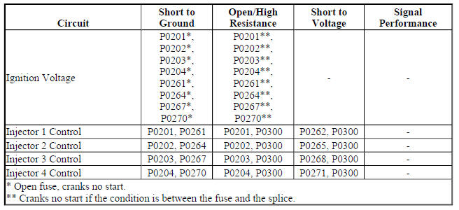
Circuit/System Description
The engine control module (ECM) enables the appropriate fuel injector pulse for each cylinder. Ignition voltage is supplied to the fuel injectors. The ECM controls each fuel injector by grounding the control circuit via a solid state device called a driver.
Reference Information
Schematic Reference
Engine Controls Schematics (Encore) , Engine Controls Schematics (Encore)
Connector End View Reference
WIRING SYSTEMS AND POWER MANAGEMENT - COMPONENT CONNECTOR END VIEWS - INDEX - ENCORE WIRING SYSTEMS AND POWER MANAGEMENT - COMPONENT CONNECTOR END VIEWS - INDEX - Encore
Electrical Information Reference
- Circuit Testing
- Connector Repairs
- Testing for Intermittent Conditions and Poor Connections
- Wiring Repairs
Scan Tool Reference
Control Module References
Special Tool
CH 34730-2C Noid Light
Circuit/System Verification
- Engine cranking or running.
- Verify the scan tool parameters listed below do not display Malfunction.
- Cylinder 1-4 Injector Control Circuit Low Voltage Test Status
- Cylinder 1-4 Injector Control Circuit Open Test Status
- Cylinder 1-4 Injector Control Circuit High Voltage Test Status
- If Malfunction is displayed
Refer to Circuit/System Testing.
- If Malfunction is not displayed
- All OK.
Circuit/System Testing
- Ignition OFF, disconnect the harness connector at a Q17 Fuel Injector, ignition ON.
- Verify a test lamp illuminates between the ignition circuit terminal 1 and ground.
- If the test lamp does not illuminate and the circuit fuse is good
- Ignition OFF, remove the test lamp.
- Test for less than 2 ohms in the ignition circuit end to end.
- If 2 ohms or greater, repair the open/high resistance in the circuit.
- If less than 2 ohms, verify the fuse is not open and there is voltage at the fuse.
- If the test lamp does not illuminate and the circuit fuse is open
- Ignition OFF, remove the test lamp.
- Test for infinite resistance between the ignition circuit and ground.
- If less than infinite resistance, repair the short to ground on the circuit.
- If infinite resistance, test all components connected to the ignition voltage circuit for a short and replace as necessary.
- If the test lamp illuminates
- Verify that a test lamp does not illuminate between the ignition circuit 1 and the control circuit 2.
- If the test lamp illuminates
- Ignition OFF, remove the test lamp, disconnect the harness connector at the K20 Engine Control Module.
- Test for infinite resistance between the control circuit and ground.
- If less than infinite resistance, repair the short to ground on the circuit.
- If infinite resistance, replace the K20 Engine Control Module.
- If the test lamp does not illuminate
- Ignition OFF, connect the CH 34730-2C Noid Light to a fuel injector connector.
- Engine cranking.
- Verify the CH 34730-2C Noid Light turns ON and OFF for each fuel injector connector.
- If the CH 34730-2C is always OFF
- Ignition OFF, remove the CH 34730-2C Noid Light , disconnect the harness connector at the K20 Engine Control Module, ignition ON.
- Test for less than 1 V between the control circuit and ground.
- If 1 V or greater, repair the short to voltage on the circuit.
- If less than 1 V
- Ignition OFF.
- Test for less than 2 ohms in the control circuit end to end.
- If 2 ohms or greater, repair the open/high resistance in the circuit.
- If less than 2 ohms, replace the K20 Engine Control Module.
- If the CH 34730-2C is always ON
- Ignition OFF, remove the CH 34730-2C Noid Light , disconnect the harness connector at the K20 Engine Control Module.
- Test for infinite resistance between the control circuit and ground.
- If less than infinite resistance, repair the short to ground on the circuit.
- If infinite resistance, replace the K20 Engine Control Module.
- If the CH 34730-2C turns ON and OFF
- Test or replace the Q17 Fuel Injector.
Component Testing
Fuel Injector Diagnosis
Repair Instructions
Perform the Diagnostic Repair Verification after completing the repair.
- Fuel Injector Replacement
- Control Module References for Engine Control Module replacement, programming, and setup.
Alcohol/contaminants-in-fuel diagnosis
Diagnostic Instructions
- Perform the Diagnostic System Check - Vehicle prior to using this diagnostic procedure.
- Review Strategy Based Diagnosis for an overview of the diagnostic approach.
- Diagnostic Procedure Instructions provides an overview of each diagnostic category.
Test Description
Water contamination in the fuel system may cause driveability conditions such as hesitation, stalling, no start, or misfires in one or more cylinders. Water may collect near a single fuel injector at the lowest point in the fuel injection system and cause a misfire in that cylinder. If the fuel system is contaminated with water, inspect the fuel system components for rust or deterioration.
Ethanol concentrations of greater than 10 percent can cause driveability conditions and fuel system deterioration. Fuel with more than 10 percent ethanol could result in driveability conditions such as hesitation, lack of power, stalling, or no start. Excessive concentrations of ethanol used in vehicles not designed for it may cause fuel system corrosion, deterioration of rubber components, and fuel filter restriction.
Reference Information
Special Tool
CH 44175-A Fuel Composition Tester , if available
For equivalent regional tools, refer to Special Tools (Diagnostic Tools) .
System Verification
The fuel sample should be drawn from the bottom of the tank so that any water present in the tank will be detected. The sample should be bright and clear.
- If the sample appears cloudy, or contaminated with water, as indicated by a water layer at the bottom of the sample, perform the Particulate Contaminants in Fuel Testing Procedure.
- If alcohol contamination is suspected, perform the Alcohol in Fuel Testing procedure.
Alcohol in Fuel Testing with Special Tool, If Available
- Test the fuel composition using the CH 44175-A Fuel Composition Tester and the Instruction Manual.
- If water appears in the fuel sample, clean the fuel system.
- Subtract 50 from the reading on the DMM in order to obtain the percentage of alcohol in the fuel sample.
- If the fuel sample contains more than 15 percent ethanol, add fresh, regular gasoline to the vehicle's fuel tank.
- Test the fuel composition.
- If testing shows the ethanol percentage is still more than 15 percent, replace the fuel in the vehicle.
Alcohol in Fuel Testing without Special Tool
- Using a 100 ml (3.38 oz) specified cylinder with 1 ml (0.034 oz) graduation marks, fill the cylinder with fuel to the 90 ml (3.04 oz) mark.
- Add 10 ml (0.34 oz) of water in order to bring the total fluid volume to 100 ml (3.38 oz) and install a stopper.
- Shake the cylinder vigorously for 10-15 seconds.
- Carefully loosen the stopper in order to release the pressure.
- Re-install the stopper and shake the cylinder vigorously again for 10-15 seconds.
- Put the cylinder on a level surface for approximately 5 min in order to allow adequate liquid separation. If alcohol is present in the fuel, the volume of the lower layer, which would now contain both alcohol and water, will be more than 10 ml (0.34 oz). For example, if the volume of the lower layer is increased to 15 ml (0.51 oz), this indicates at least 5 percent alcohol in the fuel. The actual amount of alcohol may be somewhat more because this procedure does not extract all of the alcohol from the fuel.
Particulate Contaminants in Fuel Testing Procedure
- Using an approved fuel container, draw approximately 0.5 liter (0.53 qt) of fuel.
- Place the container on a level surface for approximately 5 min in order to allow settling of the particulate contamination. Particulate contamination will show up in various shapes and colors. Sand will typically be identified by a white or light brown crystals. Rubber will appear as black and irregular particles.
- Observe the fuel sample. If any physical contaminants or water are present, clean the fuel system.
Repair Instructions
Perform the Diagnostic Repair Verification after completing the diagnostic procedure.
- Fuel System Cleaning
- Fuel Tank Draining
Evaporative emission control system diagnosis
Special Tools
EN 41413-VLV EVAP Service Port Vent Fitting
Operating Instructions for the Evaporative Emission System Tester (EEST)
Vehicle Setup
WARNING: Refer to Fuel and Evaporative Emission Pipe Warning .
CAUTION: Refer to Clean, Dry, Low Pressure Gas Source Caution
NOTE: When servicing the EVAP system, test pressure must not exceed 13 in H20 (0.5 PSI) as pressure in excess of this could cause system components to perform inaccurately.
NOTE: A large difference between the vehicle temperature and shop temperature will seriously affect the accuracy of the tests. Always allow at least 15 min for the vehicle temperature to adjust to the shop temperature. Refer to Temperature Variation Instructions for more information about vehicle versus shop temperatures.
- Engine OFF, open the hood. Position a large fan to blow air under the vehicle onto the fuel tank area.
- Connect the red battery clip from the tester to the positive battery terminal.
NOTE: The vehicle battery must be fully charged for optimum tester performance.
- Connect the black battery clip from the tester to chassis ground.
Flow Meter Test - Leak Detection
CAUTION: Refer to Fuel and Evaporative Emission Hose/Pipe Connection Cleaning Caution
- Open the Nitrogen tank valve and turn the NITROGEN/SMOKE valve on the front control panel to NITROGEN.
- Connect the hose to the correct test orifice on the bottom front of the tester. For orifice size, refer to the vehicle specific information found in service procedures for DTCs that relate to evaporative emission (EVAP) system leaks.
- Press and release the remote switch to activate the tester.
NOTE: The tester will time out after about 15 min. You may press the remote switch to reactivate the tester as desired.
- Position the sliding red flag on the flow meter to align with the floating indicator. When the red flag is set, press and release the remote switch to deactivate the tester.
- Remove the hose from the test orifice and install the hose onto the vehicle. For proper connection location, and the special tool numbers for any adapters that may be required, refer to the service procedures for DTCs that relate to EVAP system leaks.
- Ignition ON, seal the EVAP system per instructions in the service procedures for DTCs that relate to EVAP system leaks. Most systems can be sealed using a scan tool output control for the EVAP Vent Solenoid Valve, other systems require that the vent system be plugged.
NOTE:
- Larger volume fuel tanks, and/or those with lower fuel levels, may require several minutes to fill with nitrogen.
- Static buildup may cause the float indicator to stick. It may be necessary to tap on the flow meter to free up the float.
- If fuel level is 90 % or greater it will take longer to fill the system with smoke because the fuel fill tube check valve will be closed and force any smoke to pass through the ORVR pipe and orifice.
- Press and release the remote switch to activate the nitrogen flow and fill the system.
- Compare the stable floating indicator position to the red flag.
- Below the red flag, the result is acceptable, Pass. Test complete
- Above the red flag, the result is unacceptable, Fail. Go to the Smoke Procedure
- Press and release the remote switch to deactivate the tester.
Smoke Procedure - Locate the Leak
NOTE: It is not recommended to use the tester in an outside repair bay area because wind and sunlight may affect temperature and your ability to see the smoke.
- Turn OFF any fans that may cause air movement around or near the vehicle.
NOTE: Completely unwind the nitrogen/smoke hose from the bracket to optimize the tester's performance.
- Connect the nitrogen/smoke hose to the vehicle as directed in the service procedures. Some vehicles require that the nitrogen/smoke hose be connected at the front of the EVAP system at the EVAP service port. An adapter may be necessary. Other vehicles require the connection be made at the rear of the system using an adapter at the fuel fill cap. Consult the service procedures for DTCs that relate to evaporative emission (EVAP) system leaks for vehicle specific instructions regarding connection location and adapters.
- Open the Nitrogen tank valve and turn the nitrogen/smoke valve on the control panel to smoke.
NOTE: The remote switch operates on a push ON, push OFF fashion.
- Press and release the remote switch to activate the tester and inject smoke into the EVAP system.
- Verify smoke has filled the EVAP system by opening the system opposite the end where smoke is injected. When injecting smoke at the service port, remove the fuel fill cap until smoke is observed. Then close the system and continue testing. If using a special tool fuel fill cap adapter at the filler neck, vent the system at the service port, with special tool EN 41413-VLV EVAP Service Port Vent Fitting, until smoke is observed then remove the vent fitting tool and close the system to continue with the test.
NOTE: Inject smoke in less than 2 min cycles for optimum tester performance.
- Press and release the remote switch to deactivate the tester.
NOTE: For optimum visual smoke performance, deactivate the smoke flow and allow the system pressure to drop. Allowing the smoke to exit small holes at a low flow rate greatly enhances visibility.
- Introduce smoke into the system for an additional 60 s. Continue introducing smoke at 15 s intervals, as necessary.
- Using a high-intensity white light, inspect the entire EVAP system path, and look for the source of the leak indicated by the exiting smoke. Introduce smoke at 15 s intervals, as needed, until leak source is identified.
Temperature Variation Instructions
The Concern
Ideal circumstances for conducting the EVAP flow meter test require equal temperatures between the Nitrogen gas and the vehicle EVAP system. Significant differences in temperature between them can result in a flow or pressure change during testing, causing misleading results. Typically, the EEST is stored indoors, approximately 21ºC (70ºF). Vehicles brought in for diagnosis may have an EVAP system at significantly different temperatures.
For Example
NOTE: With no temperature difference between the Nitrogen gas and EVAP system, the resulting vehicle EVAP system pressure will remain stable at 3.2 kPa, 13 in. H2O (0.5 PSI) once pressurized, providing no leaks are present.
When the EVAP flow meter tests are performed with significant differences in temperature between the Nitrogen gas and the vehicle EVAP system, the following results can occur:
- An increase in flow during the flow meter test can be caused by a vehicle's warm EVAP system cooling down.
- A decrease in flow during the flow meter test can be caused by a vehicle's cool EVAP system warming up.
The Solution
When working on a vehicle with significant temperature differences between the vehicle EVAP system and the Nitrogen gas, allow the vehicle EVAP system temperature to stabilize as close as possible to the temperature of the Nitrogen gas before conducting the Flow Meter Test.
Electronic ignition system diagnosis
Diagnostic Instructions
- Perform the Diagnostic System Check - Vehicle prior to using this diagnostic procedure.
- Review Strategy Based Diagnosis for an overview of the diagnostic approach.
- Diagnostic Procedure Instructions provides an overview of each diagnostic category.
Circuit/System Description
This ignition system uses an ignition coil module. The engine control module (ECM) controls the spark events by transmitting the timing pulses on the ignition control (IC) circuits to the cylinder ignition coils in firing order sequence.
Diagnostic Aids
- An open/high resistance on the low reference circuit to the ignition coil may cause a misfire.
- An erratic or weak spark is considered a no spark condition.
Reference Information
Schematic Reference
Engine Controls Schematics (Encore) , Engine Controls Schematics (Encore)
Connector End View Reference
WIRING SYSTEMS AND POWER MANAGEMENT - COMPONENT CONNECTOR END VIEWS - INDEX - ENCORE WIRING SYSTEMS AND POWER MANAGEMENT - COMPONENT CONNECTOR END VIEWS - INDEX - Encore
Description and Operation
Electronic Ignition System Description
Electrical Information Reference
- Circuit Testing
- Connector Repairs
- Testing for Intermittent Conditions and Poor Connections
- Wiring Repairs
Scan Tool Reference
Control Module References
Circuit/System Testing
NOTE: Do not perform this diagnostic procedure unless you were sent here from a misfire DTC or the Engine Cranks But Does Not Run diagnostic.
- Ignition OFF and all vehicle systems OFF, disconnect the harness connector at the K35 Ignition Coil Module. It may take up to 2 min for all vehicle systems to power down.
- Test for less than 5 ohms between the ground circuit terminal B and ground.
- If 5 ohms or greater
- Ignition OFF.
- Test for less than 2 ohms in the ground circuit end to end.
- If 2 ohms or greater, repair the open/high resistance in the circuit.
- If less than 2 ohms, repair the open/high resistance in the ground connection.
- If less than 5 ohms
- Test for less than 5 ohms between the low reference circuit terminal C and ground.
- If 5 ohms or greater
- Ignition OFF, disconnect the X2 harness connector at the K20 Engine Control Module.
- Test for less than 2 ohms in the low reference circuit end to end.
- If 2 ohms or greater, repair the open/high resistance in the circuit.
- If less than 2 ohms, replace the K20 Engine Control Module.
- If less than 5 ohms
- Ignition ON.
- Verify a test lamp illuminates between the ignition circuit terminal A and ground.
- If the test lamp does not illuminate and the circuit fuse is good
- Ignition OFF, remove the test lamp.
- Test for less than 2 ohms in the ignition circuit end to end.
- If 2 ohms or greater, repair the open/high resistance in the circuit.
- If less than 2 ohms, verify the fuse is not open and there is voltage at the fuse.
- If the test lamp does not illuminate and the circuit fuse is open
NOTE: The ignition circuit may supply voltage to other components. Make sure to test all circuits and components for a short to ground that share the ignition circuit.
- Ignition OFF, remove the test lamp, and disconnect all components on the circuit.
- Test for infinite resistance between the ignition circuit and ground.
- If less than infinite resistance, repair the short to ground on the circuit.
- If infinite resistance
- Replace the fuse, ignition ON.
- Verify the fuse is good after connecting each of the components one at a time.
- If the fuse opens, replace the component that opens the fuse when connected.
- If the fuse is good, all OK.
- If the test lamp illuminates
- Replace the K35 Ignition Coil Module.
Repair Instructions
Perform the Diagnostic Repair Verification after completing the repair.
- Ignition Coil Replacement
- Control Module References for engine control module replacement, programming, and setup.
Inspection/maintenance system check
Diagnostic Instructions
- Perform the Diagnostic System Check - Vehicle prior to using this diagnostic procedure.
- Review Diagnostic System Check - Vehicle for an overview of the diagnostic approach.
- Diagnostic Procedure Instructions provides an overview of each diagnostic category
Circuit/System Description
Several states require for a vehicle to pass on-board diagnostic (OBD) system tests and inspection/maintenance (I/M) emission inspections in order to renew license plates. This is accomplished by viewing the Inspection/Maintenance System Status or Data display on a scan tool. Using a scan tool, the technician can observe the I/M status in order to verify that the vehicle meets the criteria that complies with the local area requirements.
Condition for Updating the Inspection/Maintenance Emission System Status
Each system monitor requires at least one, and sometimes several, diagnostic tests. The result of each test is reported by a diagnostic trouble code (DTC). A system monitor is complete when either all of the DTCs composing the monitor have Run and Passed, or when any one of the DTCs comprising the monitor has illuminated the malfunction indicator lamp (MIL). Once the system monitor is complete, the Inspection/Maintenance System Status or Data will indicate YES in the completed or Value column.
For example, when the HO2S heater status indicates YES, either all of the oxygen sensor heater tests have passed or one of the tests has illuminated the MIL. If the vehicle has two heated oxygen sensors, either both heater circuit tests have passed or one of the heater circuit tests has illuminated the MIL. The Inspection/Maintenance System Status or Data will indicate NO under the Completed or Value column when any of the required tests for that system have not run. The following is a list of conditions that may set the Inspection/Maintenance System Status or Data indicator to NO:
- The vehicle is new from the factory and has not yet been driven through the necessary drive conditions to complete the tests.
- The battery has been disconnected or discharged below operating voltage.
- The engine control module (ECM) power or ground has been interrupted.
- The ECM has been reprogrammed.
- The ECM DTCs have been cleared.
Monitored Emission Control Systems
The OBD II System monitors all emission control systems that are on-board. The OBD II regulations require monitoring of the following:
- The air conditioning system
- The catalyst efficiency
- Comprehensive component monitoring, emission related inputs and outputs
- The evaporative emission (EVAP) system
- The fuel delivery system
- Heated catalyst monitoring
- Misfire monitoring
- The oxygen sensor system (HO2S)
- The oxygen sensor heater system (HO2S heater)
For the specific DTCs required for each system, refer to Inspection/Maintenance (I/M) System DTC Table.
Systems such as fuel delivery, misfire, and comprehensive components may not be listed in a system status list.
These tests run continuously and do not require an inspection/maintenance system status indicator.
Circuit/System Verification
- Verify that all Inspection/Maintenance System Status or Data indicators report YES, and that no I/M Test DTCs are present.
- If any I/M Test DTCs are set
Refer to Diagnostic Trouble Code (DTC) List - Vehicle .
- If no I/M Test DTCs are set
- All OK.
Circuit/System Testing
NOTE: Many DTC related repairs will instruct the technician to clear the DTC information. Clearing the DTC will reset the Inspection/Maintenance System Status or Data indicators to NO. Performing the I/M Complete System Set Procedure will set each of the I/M System Status indicators to YES.
- Verify no I/M DTCs are present.
- If an I/M DTC is set that would prevent the I/M System Status tests from completing, diagnose that DTC before continuing.
Refer to Inspection/Maintenance (I/M) System DTC Table.
- If no I/M DTCs are set
- Review applicable service bulletins for software updates that would prevent the I/M System Status tests from completing.
- If a control module re-program or other repair is required,
Perform the Inspection/Maintenance Complete System Set Procedure after repair.
- If no repair is required
- Observe the Inspection/Maintenance System Status or Data indicators.
- If any Inspection/Maintenance System Status or Data indicators report NO
Perform the Inspection/Maintenance Complete System Set Procedure.
- If no Inspection/Maintenance System Status or Data indicators report NO
- All OK.
Inspection/maintenance complete system set procedure
Diagnostic Instructions
- Perform the Diagnostic System Check - Vehicle prior to using this diagnostic procedure.
- Review Strategy Based Diagnosis for an overview of the diagnostic approach.
- Diagnostic Procedure Instructions provides an overview of each diagnostic category.
Circuit/System Description
The purpose of the inspection/maintenance complete system set procedure is to satisfy the enable criteria necessary to execute all of the inspection/maintenance readiness diagnostics and complete the trips for those particular diagnostics. When all inspection/maintenance monitored diagnostic tests are completed, the inspection/maintenance system status indicators are set to yes. Perform the inspection/maintenance complete system set procedure if any inspection/maintenance system status indicators are set to NO.
Condition for Meeting a Cold Start
- The ignition voltage between 10-18 V.
- The barometric pressure (BARO) is more than 75 kPa (10.15 PSI).
- The engine coolant temperature (ECT) at start-up is greater than -5ºC (23ºF).
- The intake air temperature (IAT) at start-up is less than 40ºC (104ºF).
- The difference between the start-up IAT and ECT are within 3ºC (5ºF).
- The engine is OFF for greater than 6 h or the following conditions must be met:
- The start-up IAT minus start-up ECT 1 are within 12ºC (22ºF).
- The start-up ECT minus start-up IAT are within 50ºC (90ºF).
- Fuel level is between 25-75%.
Circuit/System Verification
- Verify that all I/M System Status indicators report YES, and that no I/M Test DTCs are present.
- If any I/M Test DTCs are set
Refer to Diagnostic Trouble Code (DTC) List - Vehicle .
- If no I/M Test DTCs are set
- All OK.
Inspection/Maintenance System Set Procedure
NOTE: Whenever the ignition is turned ON, ignition positive voltage is supplied to the heated oxygen sensor (HO2S) heaters. After verifying the enable criteria, turn OFF the ignition for approximately 5 minutes to allow the sensors to cool before continuing with the test. Once the engine is started, do NOT turn the engine OFF for the remaining portion of the set procedure.
- Ensure that the vehicle meets the conditions for a cold start listed above.
- If the Evaporative Emission (EVAP) inspection/maintenance system status indicator displays NO, perform the EVAP Service Bay test if applicable.
- Turn OFF all accessories; HVAC system, other electrical loads, including aftermarket/add-on equipment, etc., and open the hood.
- Set the vehicle parking brake and ensure the vehicle is in park for automatic transmission or neutral for manual transmission.
- Turn the ignition ON for 1 min.
- Start and idle the engine for 5 min.
- Run the engine for 6 min within the following conditions:
- Calculated air flow is between 9-30 g/s
- Engine speed is steady between 1 300-3 000 RPM
- Apply and hold brake pedal, and shift to Drive for automatic, or apply clutch pedal for manual and operate the vehicle within the following conditions for 2 min:
- Manifold Absolute Pressure (MAP) signal is greater than 12 g/s
- Engine speed is greater than 1 000 RPM
NOTE: Do NOT touch the accelerator pedal until told to do so. A change in throttle position sensor angle or an increase in engine speed may invalidate this portion of the test.
- Release the accelerator pedal and shift the vehicle to Park for automatic, or Neutral and release clutch pedal for manual, and allow the engine to idle for 2 min.
- Close the hood, release the parking brake and drive vehicle at 90 km/h (55 MPH) for 2 min.
- Release the accelerator pedal for at least 10 s. This will allow the vehicle to enter the deceleration fuel cut off.
- Safely stop the vehicle, with the engine in drive for automatic or neutral with the clutch pedal depressed and parking brake applied for manual. Allow the vehicle to idle for 2 min.
NOTE: Do NOT disturb the vehicle or turn ON the ignition until told to do so.
Disturbing the vehicle may invalidate this portion of the test.
- Shift the vehicle to park for automatic and neutral for manual. Turn OFF
the ignition and exit the vehicle.
Do NOT disturb the vehicle for 45 min.
- Observe the Inspection/Maintenance System Status with a scan tool. All of the inspection/maintenance System Status indicators should display YES.
- If the EVAP inspection/maintenance system status indicator displays NO, turn OFF the ignition, ensure that the vehicle meets the conditions for a cold start, and repeat steps 6 through 11 three more times, or until the EVAP inspection/maintenance system status indicator transitions to yes. If the indicator continues to display NO, refer to the Inspection/Maintenance (I/M) System DTC Table to identify the DTCs that did not run.
- If any of the inspection/maintenance system status indicators display NO,
refer to the
Inspection/Maintenance (I/M) System DTC Table for the indicator which did
not display yes.
The inspection/maintenance system DTC table identifies the DTCs associated with each inspection/maintenance system status Indicator.
INSPECTION/MAINTENANCE (I/M) SYSTEM DTC TABLE
Inspection/Maintenance (I/M) System DTC Table
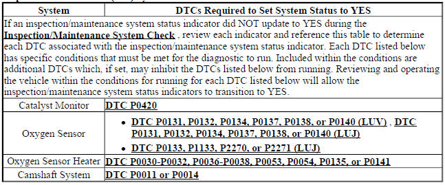
READ NEXT:
 Engine controls and fuel - 1.4l - Repair instructions
Brake pedal position sensor learn
Calibration Criteria
NOTE:
Do not apply the brake pedal during the brake pedal position sensor
calibration
procedure. Any movement of the brake pedal during this pro
Schematic wiring diagrams
ENGINE CONTROLS WIRING SCHEMATICS (ENCORE)
Module Power, Ground, Serial Data, and MIL
Fig. 1: Module Power, Ground, Serial Data, and MIL
5V1, 5V2, and Low Reference Bus (1 of 2)
Fig. 2: 5V1, 5V2,
SEE MORE:
Supplemental Inflatable Restraints - Repair instructions
MOBILE TELEPHONE MICROPHONE REPLACEMENT (ENCORE)
Fig. 15: Mobile Telephone Microphone
Mobile Telephone Microphone Replacement (Encore)
MOBILE TELEPHONE MICROPHONE REPLACEMENT (Encore)
Fig. 16: Mobile Telephone Microphone
Mobile Telephone Microphone Replacement (Encore)
COMMUNICATION INTERFAC
Lighting - Repair instructions
Brake pedal position sensor calibration
NOTE:
Brake system does not use a brake switch, stoplight switch or brakelight
switch. System uses a Brake Pedal Position Sensor to control these functions.
Calibration Criteria
NOTE:
Do not apply the brake pedal during the brake pedal position sensor
calibra
