Buick Encore: Engine controls and fuel - 1.4l - Repair instructions
Brake pedal position sensor learn
Calibration Criteria
NOTE:
Do not apply the brake pedal during the brake pedal position sensor calibration procedure. Any movement of the brake pedal during this procedure will cause the calibration procedure to fail. If this occurs, the brake pedal position sensor calibration must be repeated.
Brake pedal position sensor calibration must be performed after the brake pedal position sensor, body control module (BCM), or engine control module (ECM) have been serviced. The calibration procedure will set the brake pedal position sensor home value. This value is used by the BCM and ECM to determine the action of the driver applying the brake system and to provide this information to the vehicle subsystems via serial data
Calibration Procedure
- Apply the parking brake.
- Ignition ON, engine OFF, place the transmission in the PARK position for automatic transmission or NEUTRAL position for manual transmission.
- Install a scan tool.
- Clear all DTCs before proceeding.
- Navigate to the Configuration/Reset Functions menu of the BCM.
- Select the Brake Pedal Position Sensor Learn procedure and follow the directions displayed on the screen.
- Navigate to the Configuration/Reset Functions menu of the ECM.
- Select the Learn Functions menu.
- Select the Brake Pedal Position Sensor Learn procedure and follow the directions displayed on the screen.
ENGINE CONTROL MODULE REPLACEMENT
.gif)
Fig. 1: Engine Control Module
Engine Control Module Replacement
.jpg)
.jpg)
CRANKSHAFT POSITION SYSTEM VARIATION LEARN
NOTE: The crankshaft position sensor system variation learn procedure is required when the following service procedures have been performed, regardless of whether DTC P0315 is set:
- Engine replacement
- Engine control module (ECM) replacement
- Crankshaft damper replacement
- Crankshaft replacement
- Crankshaft Position Sensor Replacement
- Any engine repairs which disturb the crankshaft to crankshaft position sensor relationship.
NOTE: The ECM monitors certain component signals to determine if all the conditions are met to continue with the Crankshaft Position Variation Learn procedure.
- Ignition ON, observe the DTC information with a scan tool. Verify no other DTCs are set, except DTCs P0300-P0304, or P0315.
- If DTCs are set, except DTCs P0300-P0304, or P0315, refer to Diagnostic Trouble Code (DTC) List - Vehicle for further diagnosis.
- Select the Crankshaft Position Variation Learn Procedure with a scan tool and follow the on screen instructions:
- Verify DTC P0315 does not set.
- If DTC P0315 set, or another DTC is present refer to Diagnostic Trouble Code (DTC) List - Vehicle for the applicable DTC that set.
- If the DTC does not set
- All OK.
ENGINE COOLANT TEMPERATURE SENSOR REPLACEMENT (WATER OUTLET)
.gif)
Fig. 2: Engine Coolant Temperature Sensor (Water Outlet)
Engine Coolant Temperature Sensor Replacement (Water Outlet)
.jpg)
.jpg)
ENGINE COOLANT TEMPERATURE SENSOR REPLACEMENT (RADIATOR)
.gif)
Fig. 3: Engine Coolant Temperature Sensor (Radiator)
Engine Coolant Temperature Sensor Replacement (Radiator)
.jpg)
MASS AIRFLOW SENSOR REPLACEMENT
.gif)
Fig. 4: Mass Airflow Sensor
Mass Airflow Sensor Replacement
.jpg)
INTAKE AIR PRESSURE AND TEMPERATURE SENSOR REPLACEMENT
.gif)
Fig. 5: Intake Air Pressure and Temperature Sensor
Intake Air Pressure and Temperature Sensor Replacement
.jpg)
MANIFOLD ABSOLUTE PRESSURE SENSOR REPLACEMENT
.gif)
Fig. 6: Manifold Absolute Pressure Sensor
Manifold Absolute Pressure Sensor Replacement
.jpg)
TURBOCHARGER WASTEGATE REGULATOR SOLENOID VALVE REPLACEMENT
.gif)
Fig. 7: Turbocharger Wastegate Regulator Solenoid Valve
Turbocharger Wastegate Regulator Solenoid Valve Replacement
.jpg)
HEATED OXYGEN SENSOR REPLACEMENT - SENSOR 1
.gif)
Fig. 8: Heated Oxygen Sensor 1
Heated Oxygen Sensor Replacement - Sensor 1
.jpg)
.jpg)
HEATED OXYGEN SENSOR REPLACEMENT - SENSOR 2
.gif)
Fig. 9: Heated Oxygen Sensor 2
Heated Oxygen Sensor Replacement - Sensor 2
.jpg)
ENGINE OIL PRESSURE INDICATOR SWITCH REPLACEMENT
.gif)
Fig. 10: Engine Oil Pressure Indicator Switch
Engine Oil Pressure Indicator Switch Replacement
.jpg)
ACCELERATOR PEDAL POSITION SENSOR REPLACEMENT
.gif)
Fig. 11: Accelerator Pedal Position Sensor & Fastener
Accelerator Pedal Position Sensor Replacement
.jpg)
Throttle body assembly replacement
Removal Procedure
- Disconnect the throttle body wiring harness connector.
- Remove the charge air cooler outlet air hose from the throttle body. Refer to Charge Air Cooler Outlet Air Hose Replacement.
.gif)
Fig. 12: Throttle Body
- Remove the 4 throttle body fasteners (3).
- Remove the throttle body (2) along with the throttle body seal ring (1).
Installation Procedure
.gif)
Fig. 13: Throttle Body
- Install the throttle fasteners (3) along with a NEW throttle body seal ring (1).
CAUTION: Refer to Fastener Caution .
- Install the 4 throttle body fastener (3) and tighten to 8 (71 lb in).
- Install the charge air cooler outlet air hose to the throttle body. Refer to Charge Air Cooler Outlet Air Hose Replacement.
- Connect the throttle body wiring harness connector.
- Perform the throttle/idle learn. Refer to Q38 Throttle Body: Throttle/Idle Learn.
Throttle body inspection and cleaning
NOTE:
Over extended time and mileage, deposits may accumulate on the back of the throttle valve plate. The source of the deposit is exhaust gas. Typically these deposits pose no problem. Occasionally the deposit may accumulate to a point where perceived pedal effort or throttle valve movement is effected. This procedure should not be performed on vehicles with mileage under 80,450 km (50,000 mi).
- Remove the charge air cooler outlet air hose. Refer to Charge Air Cooler Outlet Air Hose Replacement.
WARNING: Turn OFF the ignition before inserting fingers into the throttle bore.
Unexpected movement of the throttle blade could cause personal injury.
CAUTION: Do not insert any tools into the throttle body bore in order to avoid damage to the throttle valve plate.
- Inspect the throttle body bore and the throttle valve plate for deposits. You will need to open the throttle valve in order to inspect all surfaces.
CAUTION: Do not use any solvent that contains Methyl Ethyl Ketone (MEK). This solvent may damage fuel system components.
- Clean the throttle body bore and the throttle valve plate using a clean shop towel with an appropriate cleaner.
- Install the charge air cooler outlet air hose. Refer to Charge Air Cooler Outlet Air Hose Replacement.
FUEL PRESSURE RELIEF
WARNING: Refer to Gasoline/Gasoline Vapors Warning .
WARNING: Remove the fuel tank cap and relieve the fuel system pressure before servicing the fuel system in order to reduce the risk of personal injury.
After you relieve the fuel system pressure, a small amount of fuel may be released when servicing the fuel lines, the fuel injection pump, or the connections. In order to reduce the risk of personal injury, cover the fuel system components with a shop towel before disconnection. This will catch any fuel that may leak out. Place the towel in an approved container when the disconnection is complete.
- Disconnect the battery. Refer to Battery Negative Cable Disconnection and Connection
- Loosen the fuel fill cap in order to relieve the fuel tank vapor pressure.
- Remove the engine cover, if required.
- Remove the fuel rail service port cap.
- Wrap a shop towel around the fuel rail service port and using a small flat bladed tool, depress (open) the fuel rail test port valve.
- Remove the shop towel from around the fuel rail service port, and place in an approved gasoline container.
- Install the fuel rail service port cap.
- Install the engine cover, if required.
- Tighten the fuel fill cap.
Fuel tank draining
Special Tool
CH 45004 Fuel Tank Drain Hose
WARNING: Never drain or store fuel in an open container. Always use an approved fuel storage container in order to reduce the chance of fire or explosion.
WARNING: Place a dry chemical (Class B) fire extinguisher nearby before performing any on-vehicle service procedures. Failure to follow these precautions may result in personal injury.
- Remove the fuel fill cap.
.gif)
Fig. 14: Fuel Sender O-Ring Gasket
- Remove the fuel tank sender. Refer to Fuel Sender Assembly Replacement (AWD).
- With the fuel tank sender (1) and seal (2) removed, insert the CH 45004 hose into the fuel tank until the bottom is reached.
- Using an appropriate pump or syphon, drain as much fuel from the tank as possible.
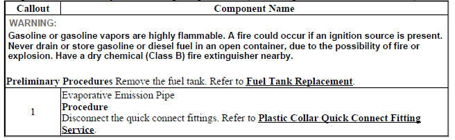
FUEL TANK REPLACEMENT
Removal Procedure
WARNING: Gasoline or gasoline vapors are highly flammable. A fire could occur if an ignition source is present. Never drain or store gasoline or diesel fuel in an open container, due to the possibility of fire or explosion. Have a dry chemical (Class B) fire extinguisher nearby. WARNING: Always wear safety goggles when working with fuel in order to protect the eyes from fuel splash.
- Relieve the fuel system pressure. Refer to Fuel Pressure Relief.
- Drain the fuel tank. Refer to Fuel Tank Draining.
- Raise and support the vehicle. Refer to Lifting and Jacking the Vehicle .
- Remove the exhaust. Refer to Exhaust Muffler Replacement (LUV) .
- Remove the propeller shaft. Refer to Two-Piece Propeller Shaft Replacement .
- Remove the right rear wheelhouse panel liner. Refer to Rear Wheelhouse Liner Replacement .
.gif)
Fig. 15: Fuel Tank Fuel Pump Module Wiring Harness
- Disconnect the fuel tank fuel pump module wiring harness (1) and unclip the fuel tank module wiring harness from the chassis.
- Disconnect the fuel tank filler pipe. Refer to Fuel Tank Filler Pipe Replacement.
- Disconnect the fuel feed pipe. Fuel Feed Pipe Replacement (At Tank AWD)
- Disconnect the EVAP system hoses. Refer to Evaporative Emission System Hose/Pipe Replacement (Fuel Pump Module to Canister AWD)Evaporative Emission System Hose/Pipe Replacement (Canister to Pipe AWD).
- Position a suitable hydraulic lift below the fuel tank.
.gif)
Fig. 16: Fuel Tank Straps And Fasteners
- Remove both fuel tank strap fasteners (1).
- Remove both fuel tank straps from the fuel tank (2).
WARNING: To help avoid personal injury, always use jack stands when you are working on or under any vehicle that is supported only by a jack.
CAUTION: When you are jacking or lifting a vehicle at the frame side rails or other prescribed lift points, be certain that the lift pads do not contact the catalytic converter, the brake pipes or the fuel lines. If such contact occurs, vehicle damage or unsatisfactory vehicle performance may result.
- With the aid of an assistant, lower the hydraulic lift to remove the fuel tank from the vehicle.
- Remove the fuel tank from the hydraulic lift.
- Remove the fuel tank fuel pump module. Refer to Fuel Tank Fuel Pump Module Replacement (AWD).
- Remove the fuel sender assembly. Refer to Fuel Sender Assembly Replacement (AWD).
- Remove the evaporative emission canister. Refer to Evaporative Emission Canister Replacement (AWD).
Installation Procedure
- Install the fuel sender assembly. Refer to Fuel Sender Assembly Replacement (AWD).
- Transfer the fuel tank fuel pump module. Refer to Fuel Tank Fuel Pump Module Replacement (AWD).
- Transfer the evaporative emission canister. Refer to Evaporative Emission Canister Replacement (AWD).
- Install the fuel tank to the hydraulic lift.
.gif)
Fig. 17: Fuel Tank Straps And Fasteners
- With the aid of an assistant, position the fuel tank to the vehicle.
CAUTION: Refer to Fastener Caution .
- Install both fuel tank straps to the fuel tank (2) and tighten the fasteners to 22 (16 lb ft).
- Remove the hydraulic lift from the fuel tank.
- Connect the EVAP system hoses. Refer to Evaporative Emission System Hose/Pipe Replacement (Fuel Pump Module to Canister AWD)Evaporative Emission System Hose/Pipe Replacement (Canister to Pipe AWD).
- Connect the fuel feed pipe. Refer to Fuel Feed Pipe Replacement (At Tank AWD).
- Connect the fuel tank filler pipe. Refer to Fuel Tank Filler Pipe Replacement.
.gif)
Fig. 18: Fuel Tank Fuel Pump Module Wiring Harness
- Connect the fuel tank fuel pump module wiring harness (1) and clip the fuel tank module wiring harness to the chassis.
- Install the propeller shaft. Refer to Two-Piece Propeller Shaft Replacement .
- Install the exhaust. Refer to Exhaust Muffler Replacement (LUV)
- Install the right rear wheelhouse panel liner. Refer to Rear Wheelhouse Liner Replacement .
- Lower the vehicle.
Fuel tank filler pipe replacement
Removal Procedure
WARNING: Gasoline or gasoline vapors are highly flammable. A fire could occur if an ignition source is present. Never drain or store gasoline or diesel fuel in an open container, due to the possibility of fire or explosion. Have a dry chemical (Class B) fire extinguisher nearby.
- Remove the fuel cap.
- Remove the right rear tire and wheel assembly. Refer to Tire and Wheel Removal and Installation .
- Remove the right rear wheelhouse panel liner. Refer to Rear Wheelhouse Liner Replacement .
.gif)
Fig. 19: Fuel Tank Filler Pipe
- Remove the fuel tank filler pipe fastener (1).
- Raise and support the vehicle. Refer to Lifting and Jacking the Vehicle .
.gif)
Fig. 20: Fuel Tank Filler Pipe Quick Connect Fitting
- Remove the fuel tank filler pipe clamp (2).
- Disconnect the fuel tank filler pipe quick connect fitting (1). Refer to Plastic Collar Quick Connect Fitting Service.
- Remove the fuel tank filler pipe fastener (3).
- Remove the fuel tank filler pipe (4) from the vehicle.
Installation Procedure
.gif)
Fig. 21: Fuel Tank Filler Pipe Quick Connect Fitting
- Install the fuel tank filler pipe (4) to the vehicle.
CAUTION: Refer to Fastener Caution .
- Install the fuel tank filler pipe fastener (3) and tighten to 9 (80 lb in).
- Connect the fuel tank filler pipe quick connect fitting (1). Refer to Plastic Collar Quick Connect Fitting Service.
- Install the fuel tank filler pipe clamp (2).
- Lower the vehicle.
.gif)
Fig. 22: Fuel Tank Filler Pipe
- Install the fuel tank filler pipe fastener (1) and tighten to 9 (80 lb in).
- Install the right rear wheelhouse panel liner. Refer to Rear Wheelhouse Liner Replacement .
- Install the right rear tire and wheel assembly. Refer to Tire and Wheel Removal and Installation .
- Install the fuel cap.
Fuel feed pipe replacement (engine to tank)
Removal Procedure
WARNING: Gasoline or gasoline vapors are highly flammable. A fire could occur if an ignition source is present. Never drain or store gasoline or diesel fuel in an open container, due to the possibility of fire or explosion. Have a dry chemical (Class B) fire extinguisher nearby.
- Relieve the fuel pressure. Refer to Fuel Pressure Relief.
- Remove the fuel pressure sensor - fuel feed pipe. Refer to Fuel Pressure Sensor Replacement - Fuel Feed Pipe.
.gif)
Fig. 23: Fuel Feed Pipe
- Remove the fuel feed pipe (1) from the fuel rail. Refer to Plastic Collar Quick Connect Fitting Service.
- Remove the fuel feed pipe (1) from the retainers (2).
- Raise and support the vehicle. Refer to Lifting and Jacking the Vehicle .
.gif)
Fig. 24: Fuel Feed Pipe And Retainers
- Remove the fuel feed pipe (1) from the fuel feed pipe at the tank. Refer to Plastic Collar Quick Connect Fitting Service.
- Remove the underbody sill shield.
- Remove the fuel feed pipe (1) from the retainers (2).
- Remove the fuel feed pipe (1) from the vehicle.
Installation Procedure
.gif)
Fig. 25: Fuel Feed Pipe And Retainers
- Install the fuel feed pipe (1) to the vehicle.
- Install the fuel feed pipe (1) to the retainers (2).
- Install the underbody sill shield.
- Install the fuel feed pipe (1) to the fuel feed pipe at the tank. Refer to Plastic Collar Quick Connect Fitting Service.
- Lower the vehicle.
.gif)
Fig. 26: Fuel Feed Pipe
- Install the fuel feed pipe (1) to the retainers (2).
- Install the fuel feed pipe (1) to the fuel rail. Refer to Plastic Collar Quick Connect Fitting Service.
- Install the fuel pressure sensor - fuel feed pipe. Refer to Fuel Pressure Sensor Replacement - Fuel Feed Pipe.
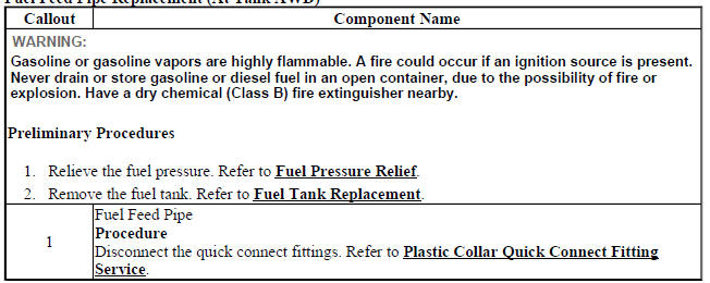
Fuel feed pipe replacement (AT TANK AWD)
.gif)
Fig. 27: Fuel Feed Pipe (At Tank - AWD)
Fuel Feed Pipe Replacement (At Tank AWD)
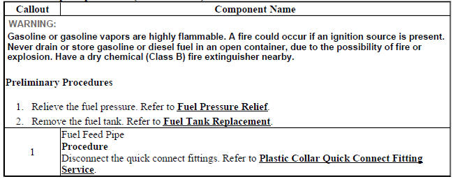
FUEL FEED PIPE REPLACEMENT (AT TANK FWD)
.gif)
Fig. 28: Fuel Feed Pipe (At Tank - FWD)
Fuel Feed Pipe Replacement (At Tank FWD)
FUEL TANK FUEL PUMP MODULE REPLACEMENT (AWD)
Special Tools
CH-45722 Fuel Pump Locking Ring Wrench
For equivalent regional tools, refer to Special Tools (Diagnostic Tools) .
Removal Procedure
WARNING: Refer to Gasoline/Gasoline Vapors Warning .
WARNING: Always wear safety goggles when working with fuel in order to protect the eyes from fuel splash.
WARNING: Do not allow smoking or the use of open flames in the area where work on the fuel or EVAP system is taking place. Anytime work is being done on the fuel system, disconnect the negative battery cable, except for those tests where battery voltage is required.
- Remove the fuel tank. Refer to Fuel Tank Replacement.
- Remove the fuel sender assembly. Refer to Fuel Sender Assembly Replacement (AWD).
- Disconnect the electrical connector.
- Remove the fuel feed pipe. Refer to Fuel Feed Pipe Replacement (At Tank AWD).
- Remove the EVAP system hoses. Refer to Evaporative Emission System Hose/Pipe Replacement (Fuel Pump Module to Canister AWD), Evaporative Emission System Hose/Pipe Replacement (Canister to Pipe AWD).
.gif)
Fig. 29: Fuel Sender Lock Ring
- Install the CH-45722 Fuel Pump Locking Ring Wrench to the fuel pump module lock ring (1).
- Using the CH-45722 Fuel Pump Locking Ring Wrench and a long breaker-bar, rotate the fuel pump module lock ring (1) in a counterclockwise direction in order to unlock the lock ring from the fuel tank (2).
.gif)
Fig. 30: Fuel Tank Vent Pipe
- Raise the fuel pump module (2) enough to gain access to the fuel tank vent pipe (1) and disconnect the pipe from the fuel pump module. Refer to Plastic Collar Quick Connect Fitting Service.
.gif)
Fig. 31: Fuel Pump Module
- Remove the fuel tank fuel pump module (2).
- Remove and discard the fuel tank fuel pump module O-ring gasket (1).
Installation Procedure
.gif)
Fig. 32: Fuel Pump Module
- Install a NEW fuel tank fuel pump module O-ring gasket (1) to the fuel tank fuel pump module (2).
.gif)
Fig. 33: Fuel Tank Vent Pipe
- Lower the fuel pump module (2) into the fuel tank while connecting the fuel tank vent pipe (1) to the fuel pump module. Refer to Plastic Collar Quick Connect Fitting Service.
.gif)
Fig. 34: Fuel Sender Lock Ring
- Install the fuel tank fuel pump module lock ring (1) to the fuel tank (2).
- Using the CH-45722 Fuel Pump Locking Ring Wrench and a long breaker-bar, rotate the fuel pump module lock ring (1) in a clockwise direction in order to lock the lock ring.
- Install the EVAP system hoses. Refer to Evaporative Emission System Hose/Pipe Replacement (Fuel Pump Module to Canister AWD), Evaporative Emission System Hose/Pipe Replacement (Canister to Pipe AWD).
- Install the fuel feed pipe. Refer to Fuel Feed Pipe Replacement (At Tank AWD).
- Connect the electrical connector.
- Install the fuel sender assembly. Refer to Fuel Sender Assembly Replacement (AWD).
- Install the fuel tank. Refer to Fuel Tank Replacement.
Fuel tank fuel pump module replacement (FWD)
Special Tools
CH-45722 Fuel Pump Locking Ring Wrench
For equivalent regional tools, refer to Special Tools (Diagnostic Tools) .
Removal Procedure
WARNING: Refer to Gasoline/Gasoline Vapors Warning .
WARNING: Always wear safety goggles when working with fuel in order to protect the eyes from fuel splash.
WARNING: Do not allow smoking or the use of open flames in the area where work on the fuel or EVAP system is taking place. Anytime work is being done on the fuel system, disconnect the negative battery cable, except for those tests where battery voltage is required.
- Remove the fuel tank. Refer to Fuel Tank Replacement.
- Disconnect the electrical connector.
- Disconnect the fuel feed pipe. Refer to Plastic Collar Quick Connect Fitting Service.
- Disconnect the evaporative emission hoses. Refer to Plastic Collar Quick Connect Fitting Service
.gif)
Fig. 35: Fuel Sender Lock Ring
- Install the CH-45722 Tool-Fuel Sender Lock Ring to the fuel pump module lock ring (1).
- Using the CH-45722 Tool-Fuel Sender Lock Ring and a long breaker-bar, rotate the fuel pump module lock ring (1) in a counterclockwise direction in order to unlock the lock ring from the fuel tank (2).
.gif)
Fig. 36: Fuel Tank Vent Pipe
- Raise the fuel pump module (2) enough to gain access to the fuel tank vent pipe (1) and disconnect the pipe from the fuel pump module. Refer to Plastic Collar Quick Connect Fitting Service.
.gif)
Fig. 37: Fuel Tank Fuel Pump Module
- Remove the fuel tank fuel pump module (2).
- Remove and discard the fuel tank fuel pump module O-ring gasket (1).
Installation Procedure
.gif)
Fig. 38: Fuel Tank Fuel Pump Module
- Install a NEW fuel tank fuel pump module O-ring gasket (1).
- Install the fuel tank fuel pump module (2).
.gif)
Fig. 39: Fuel Tank Vent Pipe
- Lower the fuel pump module (2) into the fuel tank while connecting the fuel tank vent pipe (1) to the fuel pump module. Refer to Plastic Collar Quick Connect Fitting Service
.gif)
Fig. 40: Fuel Sender Lock Ring
- Install the fuel tank fuel pump module lock ring (1) to the fuel tank (2).
- Using the CH-45722 Tool-Fuel Sender Lock Ring and a long breaker-bar, rotate the fuel pump module lock ring (1) in a clockwise direction in order to lock the lock ring.
- Connect the evaporative emission hoses. Refer to Plastic Collar Quick Connect Fitting Service.
- Connect the fuel feed pipe. Refer to Plastic Collar Quick Connect Fitting Service.
- Connect the electrical connector.
- Install the fuel tank. Refer to Fuel Tank Replacement.
Fuel tank pressure sensor replacement
.gif)
Fig. 41: Fuel Tank Pressure Sensor (FWD)
Fuel Tank Pressure Sensor Replacement
.jpg)
FUEL SENDER ASSEMBLY REPLACEMENT (AWD)
Special Tools
EN-48482 Fuel Sender Lock Ring Wrench
Removal Procedure
WARNING: Refer to Gasoline/Gasoline Vapors Warning .
WARNING: Always wear safety goggles when working with fuel in order to protect the eyes from fuel splash.
WARNING: Do not allow smoking or the use of open flames in the area where work on the fuel or EVAP system is taking place. Anytime work is being done on the fuel system, disconnect the negative battery cable, except for those tests where battery voltage is required.
- Remove the fuel tank. Refer to Fuel Tank Replacement.
- Disconnect the fuel tank wiring harness from the fuel sender.
.gif)
Fig. 42: Lock Ring
- Install the EN-48482 Fuel Sender Lock Ring Wrench to the fuel sender lock ring (1).
- Using the EN-48482 Fuel Sender Lock Ring Wrench and a long breaker-bar, rotate the fuel sender lock ring (1) in a counterclockwise direction in order to unlock the lock ring from the fuel tank (2).
.gif)
Fig. 43: Pump Module Fuel Pickup
- Raise the fuel sender (1) enough to gain access to the fuel tank fuel pump module fuel pickup (2) and disconnect the fuel sender from the fuel pickup.
.gif)
Fig. 44: Fuel Sender O-Ring Gasket
- Remove the fuel sender (1).
- Remove and discard the fuel sender O-ring gasket (2).
Installation Procedure
.gif)
Fig. 45: Fuel Sender O-Ring Gasket
- Install a NEW fuel sender O-ring gasket (2) to the fuel sender (1).
.gif)
Fig. 46: Pump Module Fuel Pickup
- Lower the fuel sender (1) into the fuel tank while connecting the fuel tank fuel pump module fuel pickup (2) to the fuel sender (1).
.gif)
Fig. 47: Lock Ring
- Install the fuel sender lock ring (1) to the fuel tank (2).
- Install the EN-48482 Fuel Sender Lock Ring Wrench to the fuel sender lock ring (1).
- Using the EN-48482 Fuel Sender Lock Ring Wrench and a long breaker-bar, rotate the fuel sender lock ring (1) in a clockwise direction in order to lock the lock ring.
- Connect the fuel tank sender wiring harness electrical connector.
- Install the fuel tank. Refer to Fuel Tank Replacement.
Chassis control module replacement
.gif)
Fig. 48: Fuel Pump Flow Control Module
Chassis Control Module Replacement
.jpg)
FUEL PUMP FLOW CONTROL MODULE REPLACEMENT
.gif)
Fig. 49: Fuel Pump Flow Control Module
Fuel Pump Flow Control Module Replacement
.jpg)
FUEL LEVEL SENSOR REPLACEMENT
.gif)
Fig. 50: Fuel Level Sensor
Fuel Level Sensor Replacement
.jpg)
FUEL PRESSURE SENSOR REPLACEMENT - FUEL FEED PIPE
.gif)
Fig. 51: Fuel Pressure Sensor - Fuel Feed Pipe
Fuel Pressure Sensor Replacement - Fuel Feed Pipe
.jpg)
Plastic collar quick connect fitting service
Removal Procedure
WARNING: Refer to Gasoline/Gasoline Vapors Warning .
NOTE: If servicing a fuel system, insure the fuel pressure has been relieved.
.gif)
Fig. 52: Plastic Collar Quick Connect Fitting Service
NOTE: There are several types of plastic collar fuel and evaporative emission quick connect fittings used on this vehicle.
- Bartholomew (1)
- Q Release (2)
- Squeeze to Release (3)
- Sliding Retainer (4)
- Global Connect (5)
- TI Loc (6)
- Safe Lock (7)
- Plastic Connector (8)
The following instructions apply to all of these types of plastic collar quick connect fittings except where indicated.
.gif)
Fig. 53: Blowing Dirt Out Of Fitting (Plastic Collar)
WARNING: Always apply a few drops of clean engine oil to the male pipe ends before connecting the fuel pipe fittings. This will ensure proper reconnection and prevent a possible fuel leak. Always replace Orings.
- Using compressed air, blow any dirt out of the quick-connect fitting.
.gif)
Fig. 54: View Of Quick Connect Fitting Release Tabs (Plastic Collar)
- This step applies to Bartholomew style connectors ONLY. Squeeze the plastic quick-connect fitting release tabs.
.gif)
Fig. 55: Releasing Q Release Style Connectors (Plastic Collar)
- This step applies to Q Release style connectors ONLY. Release the fitting by Pushing the tab toward the other side of the slot in the fitting.
.gif)
Fig. 56: Disengaging Quick Connect Fitting (Plastic Collar)
- This step applies to Squeeze to Release style connectors ONLY. Squeeze where indicated by arrows on both sides of the plastic ring surrounding the quick-connect fitting.
.gif)
Fig. 57: Pushing In Male Side Of Connector
- This step applies to Squeeze to Release style connectors ONLY. Push in the male side slightly in order to slide the retainer away from the retainers, squeeze where indicated by arrows on both sides of the plastic ring surrounding the quick-connect fitting.
.gif)
Fig. 58: View Of Sliding Retainer Style Connector
- This step applies to Sliding Retainer style connectors ONLY. Release the fitting by pressing on one side of the release tab causing it to push in slightly. If the tab doesn't move try pressing the tab in from the opposite side. The tab will only move in one direction.
.gif)
Fig. 59: Global Connector Style
- This step applies to the Global Connector style only. Push the connector toward the tube in order to release the pressure. Press and hold down the release mechanism, and pull the connector straight out.
.gif)
Fig. 60: TI Loc style
- This step applies to the TI Loc style only. Push the connector toward the tube in order to release the pressure. Release the redundant latch (1) with two fingers or a flat bladed tool. Then press and hold down the bottom release mechanism (2) and pull the connector straight out.
.gif)
Fig. 61: Safe Lock Style
WARNING: Refer to Relieving Fuel Pressure Warning .
- This step applies to the Safe Lock style only. Push the connector toward the tube in order to release the pressure. Release the second latch (1) with two fingers. Then press and hold down the bottom release mechanism (2) and pull the connector straight out.
.gif)
Fig. 62: Releasing Latch And Pulling Connector Straight Out
- This step applies to the Plastic Connector style 8, push the connector toward the tube in order to release the pressure. Press the latch (1) inward in order to release the pipe, while pulling the connector (2) straight out.
- Using a clean shop towel, wipe off the male pipe end.
- Inspect both ends of the fitting for dirt and burrs.
- Clean or replace components as necessary.
Installation Procedure
.gif)
Fig. 63: Lubricating Male Pipe End
WARNING: Always apply a few drops of clean engine oil to the male pipe ends before connecting the fuel pipe fittings. This will ensure proper reconnection and prevent a possible fuel leak. Always replace Orings.
- Apply a few drops of clean engine oil to the male pipe end.
.gif)
Fig. 64: Connecting Quick-Connect Fittings
- Push both sides of the quick-connect fitting together in order to cause the retaining feature to snap into place.
.gif)
Fig. 65: View Of Quick-Connect Fitting
- Pull on both sides of the quick-connect fitting to make sure the connection is secure.
.gif)
Fig. 66: TI Loc style
- Insert the tube in the connector until the retainer snaps in place.
- Push down on the redundant latch (1) until it is fully engaged and snapped into position.
.gif)
Fig. 67: Push Down On Redundant Latch (1) Until It Is Fully Engaged And
Snapped Into Position
- Insert the tube in the connector until the retainer snaps in place.
- Push down on the second latch (1) in order to secure the connection.
.gif)
Fig. 68: Latch And Connector
- For the plastic connector type 8, depress the latch (1) while inserting the connector (3) on to the pipe (2) .
- Move the latch (1) upward in order to secure the connection.
- Inspect for leaks using the following procedure:
- Turn the ignition ON, with the engine OFF for 2 seconds.
- Turn the ignition OFF, for 10 seconds.
- Turn the ignition ON, with the engine OFF for 2 seconds.
- Turn the ignition OFF.
- Inspect for leaks.
Fuel system cleaning
NOTE: If the fuel filter is plugged, the fuel tank should be inspected internally and cleaned if necessary.
- Drain the fuel tank. Refer to Fuel Tank Draining.
- Remove the fuel pump module assembly. Refer to Fuel Tank Fuel Pump Module Replacement (AWD), Fuel Tank Fuel Pump Module Replacement (FWD).
- Inspect the fuel pump module strainer. Replace the pump module assembly if the fuel strainer is contaminated.
NOTE: When flushing the fuel tank, handle the fuel and water mixture as a hazardous material. Handle the fuel and water in accordance with all applicable local, state, and federal laws and regulations.
- Flush the fuel tank with hot water.
- Pour the water out of the fuel sender assembly opening in the fuel tank. Rock the fuel tank in order to be sure that the removal of the water from the fuel tank is complete.
- Allow the tank to dry completely before reassembly.
- Disconnect the fuel feed pipe at the engine fuel rail. Refer to Plastic Collar Quick Connect Fitting Service.
NOTE: Only use oil-free compressed air to blow out the fuel pipes.
- Clean the fuel pipes by applying air pressure in the opposite direction of the fuel flow.
- Connect the fuel feed pipe to the engine fuel rail. Refer to Plastic Collar Quick Connect Fitting Service.
- Install the fuel pump module assembly. Refer to Fuel Tank Fuel Pump Module Replacement (AWD), Fuel Tank Fuel Pump Module Replacement (FWD).
FUEL INJECTION FUEL RAIL ASSEMBLY REPLACEMENT
Removal Procedure
- Disconnect battery negative cable. Refer to Battery Negative Cable Disconnection and Connection .
- Remove engine cover. Refer to Engine Cover Replacement .
- Remove the fuel feed pipe from fuel injection fuel rail. Refer to Fuel Feed Pipe Replacement (Engine to Tank), Fuel Feed Pipe Replacement (At Tank AWD), Fuel Feed Pipe Replacement (At Tank FWD).
- Remove the positive crankcase ventilation pipe from the intake manifold. Refer to Positive Crankcase Ventilation Pipe Removal .
.gif)
Fig. 69: Fuel Injector Wiring Harness Plugs
- Disconnect the 4 fuel injector wiring harness plugs (2).
- Unclip the ECM wiring harness from retainer clips (1) and the camshaft cover.
.gif)
Fig. 70: Fuel Injection Fuel Rail Bolts And Ground Cable Nut
- Remove the ground cable nut (2) and the ground cable.
- Remove the 2 fuel injection fuel rail bolts (1).
.gif)
Fig. 71: Fuel Injection Fuel Rail Assembly
- Remove the fuel injection fuel rail assembly (1) and the 4 fuel injector seal rings (2).
Installation Procedure
.gif)
Fig. 72: Fuel Injection Fuel Rail Assembly
NOTE: Lubricate the 4 fuel injector seal rings (2) with clean engine oil.
- Install the fuel injection fuel rail assembly (1) to the intake manifold. Use NEW fuel injector seal rings (2).
.gif)
Fig. 73: Fuel Injection Fuel Rail Bolts And Ground Cable Nut
CAUTION: Refer to Fastener Caution .
- Install the 2 fuel injection fuel rail bolts (1) and tighten to 7 N.m (62 lb in).
- Install the ground cable and the ground cable nut (2) and tighten.
.gif)
Fig. 74: Fuel Injector Wiring Harness Plugs
- Connect the 4 fuel injector wiring harness plugs (2).
- Clip the ECM wiring harness to the retainer clip (1) and the camshaft cover.
- Remove the positive crankcase ventilation pipe from the intake manifold. Refer to Positive Crankcase Ventilation Pipe Removal .
- Install the fuel feed pipe to the fuel injection fuel rail. Refer to Fuel Feed Pipe Replacement (Engine to Tank), Fuel Feed Pipe Replacement (At Tank AWD), Fuel Feed Pipe Replacement (At Tank FWD).
- Install the engine sight shield. Refer to Engine Cover Replacement .
- Connect battery negative cable. Refer to Battery Negative Cable Disconnection and Connection
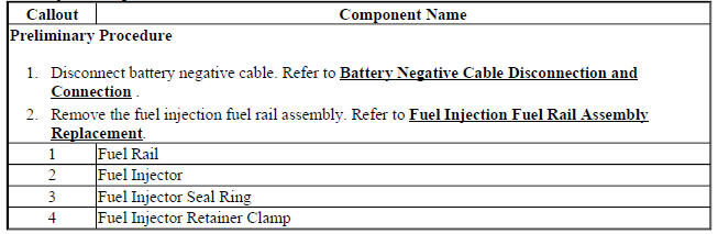
Fuel injector replacement
.gif)
Fig. 75: Fuel Injectors And Rail
Fuel Injector Replacement
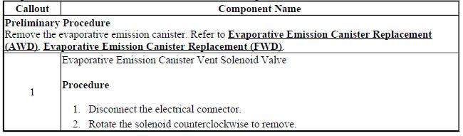
EVAPORATIVE EMISSION CANISTER VENT SOLENOID VALVE REPLACEMENT
.gif)
Fig. 76: Evaporative Emission Canister Vent Solenoid Valve
Evaporative Emission Canister Vent Solenoid Valve Replacement
EVAPORATIVE EMISSION SYSTEM HOSE/PIPE REPLACEMENT (CANISTER TO PIPE AWD)
.gif)
Fig. 77: Evaporative Emission System Hose/Pipe (canister To Pipe - AWD)
Evaporative Emission System Hose/Pipe Replacement (Canister to Pipe AWD)
.jpg)
EVAPORATIVE EMISSION SYSTEM HOSE/PIPE REPLACEMENT (CANISTER TO PIPE FWD)
.gif)
Fig. 78: Evaporative Emission System Hose/Pipe (canister To Pipe - FWD)
Evaporative Emission System Hose/Pipe Replacement (Canister to Pipe FWD)
.jpg)
EVAPORATIVE EMISSION SYSTEM HOSE/PIPE REPLACEMENT (FUEL PUMP MODULE TO CANISTER AWD)
.gif)
Fig. 79: Evaporative Emission System Hose/Pipe (Fuel Pump Module To Canister
- AWD)
Evaporative Emission System Hose/Pipe Replacement (Fuel Pump Module to Canister AWD)
.jpg)
EVAPORATIVE EMISSION SYSTEM HOSE/PIPE REPLACEMENT (FUEL PUMP MODULE TO CANISTER FWD)
.gif)
Fig. 80: Evaporative Emission System Hose/Pipe (Fuel Pump Module To Canister
- FWD)
Evaporative Emission System Hose/Pipe Replacement (Fuel Pump Module to Canister FWD)
EVAPORATIVE EMISSION CANISTER REPLACEMENT (AWD)
Fig. 81: Evaporative Emission Canister (AWD)
Evaporative Emission Canister Replacement (AWD)
.jpg)
EVAPORATIVE EMISSION CANISTER REPLACEMENT (FWD)
.gif)
Fig. 82: Evaporative Emission Canister (FWD)
Evaporative Emission Canister Replacement (FWD)
.jpg)
EVAPORATIVE EMISSION CANISTER PURGE SOLENOID VALVE REPLACEMENT
.gif)
Fig. 83: Evaporative Emission Canister Purge Solenoid Valve
Evaporative Emission Canister Purge Solenoid Valve Replacement
.jpg)
Ignition coil replacement
Special tools
- EN-6009 Remover and Installer Ignition Coil
For equivalent regional tools refer to Special Tools .
Removal Procedure
- Disconnect the battery negative cable. Refer to Battery Negative Cable Disconnection and Connection .
- Remove the engine cover. Refer to Refer to Engine Cover Replacement
.gif)
Fig. 84: Ignition Coil Wiring Harness Connector And Fasteners
- Disconnect the ignition coil wiring harness connector (1).
- Remove the 2 ignition coil fasteners (2) from the ignition coil assembly (3).
.gif)
Fig. 85: Ignition Coil Remover/Installer
- Install the EN-6009 remover/installer (1).
- Remove the ignition coil (2).
- Remove the EN-6009 remover/installer (1).
Installation Procedure
.gif)
Fig. 86: Ignition Coil Remover/Installer
- Install the EN-6009 remover/installer (1).
- Install the ignition coil assembly (2).
- Remove the EN-6009 remover/installer (1).
.gif)
Fig. 87: Ignition Coil Wiring Harness Connector And Fasteners
- Install the 2 ignition coil assembly fasteners (2) and tighten to 8 (71 lb in).
- Connect the ignition coil plug (1).
- Install the engine cover. Refer to Refer to Engine Cover Replacement .
- Connect the battery negative cable. Refer to Battery Negative Cable Disconnection and Connection .
Q38 THROTTLE BODY: Throttle/idle learn
Description
The engine control module (ECM) learns the airflow through the throttle body to ensure the correct idle. The learned airflow values are stored within the ECM. These values are learned to adjust for production variation and will continuously learn during the life of the vehicle to compensate for reduced airflow due to throttle body coking. Anytime the throttle body airflow rate changes, for example due to cleaning or replacing, the values must be relearned.
An engine that had a heavily coked throttle body that has been cleaned or replaced may take several drive cycles to unlearn the coking. To accelerate the process, the scan tool has the ability to reset all learned values back to zero. A new ECM will also have values set to zero
The idle may be unstable or a DTC may set if the learned values do not match the actual airflow.
Conditions for Running the Throttle Learn Procedure
Scan tool Idle Learn or Idle Learn Reset Procedure
- DTCs P0068, P0101, P0102, P0103, P0106, P0107, P0108, P0116, P0117, P0118, P0120, P0122, P0123, P0128, P0171, P0172, P0174, P0175, P0201-P0208, P0220, P0222, P0223, P0261, P0262, P0264, P0265, P0267, P0268, P0270, P0271, P0273, P0274, P0276, P0277, P0279, P0280, P0282, P0283, P0300-P0308, P0351-P0358, P0496, P0601, P0604, P0606, P060D, P0641, P0651, P1516, P2101, P2119, P2120, P2122, P2123, P2125, P2127, P2128, P2135, P2138, or P2176 are not set.
- Ignition ON, engine OFF.
- The vehicle speed sensor (VSS) is 0 km/h (0 mph).
Service Bay/On Road Learn Procedure
- DTCs P0068, P0101, P0102, P0103, P0106, P0107, P0108, P0116, P0117, P0118, P0120, P0122, P0123, P0128, P0171, P0172, P0174, P0175, P0201-P0208, P0220, P0222, P0223, P0261, P0262, P0264, P0265, P0267, P0268, P0270, P0271, P0273, P0274, P0276, P0277, P0279, P0280, P0282, P0283, P0300-P0308, P0351-P0358, P0496, P0601, P0604, P0606, P060D, P0641, P0651, P1516, P2101, P2119, P2120, P2122, P2123, P2125, P2127, P2128, P2135, P2138, or P2176 are not set.
- The engine speed is between 450-4,000 RPM.
- The manifold absolute pressure (MAP) is greater than 5 kPa.
- The mass air flow (MAF) is greater than 2 g/s.
- The ignition voltage is greater than 10 volts.
Throttle Learn
Scan Tool Idle Learn or Idle Learn Reset Procedure - Performed after the throttle body is cleaned or replaced
- Ignition ON, engine OFF, perform the Idle Learn or Idle Learn Reset in Configuration/Reset or Module Setup.
- Engine idling, observe the scan tool Throttle Body Idle Airflow Compensation parameter. The Throttle Body Idle Airflow Compensation value should equal 0 % and the engine should be idling at a normal idle speed.
- Clear the DTCs and return to the diagnostic that referred you here.
Service Bay/On Road Idle Learn Procedure - Performed after the ECM is programmed or replaced
NOTE: Do NOT perform this procedure if DTCs are set. Refer to Diagnostic Trouble Code (DTC) List - Vehicle .
- Engine idling for 3 min.
- Observe the scan tool Desired Idle Speed and the actual Engine Speed parameters.
- The ECM will start to learn the new idle cells and the Desired Idle Speed should start to decrease.
- Ignition OFF for 60 s.
- Start and idle the engine for 3 min.
- After the 3 min run time the engine should be idling normal.
NOTE: During the drive cycle the check engine light may come on with idle speed DTCs. If idle speed codes are set, clear codes so the ECM can continue to learn.
- If the engine idle speed has not been learned the vehicle will need to be driven at speeds above 70 km/h (44 mph) with several decelerations and extended idles.
- After the drive cycle, the engine should be idling normally.
- If the engine idle speed has not been learned, turn OFF the ignition for 60 s and repeat step 6.
- Once the engine speed has returned to normal, clear DTCs and return to the diagnostic that referred you here.
Spark plug inspection
Spark Plug Usage
- Ensure that the correct spark plug is installed. An incorrect spark plug
causes driveability conditions.
Refer to the Electronic Parts Catalog.
- Ensure that the spark plug has the correct heat range. An incorrect heat range causes the following conditions:
- Spark plug fouling-Colder plug
- Pre-ignition causing spark plug and/or engine damage-Hotter plug
Spark Plug Inspection
.gif)
Fig. 88: Cross Sectional View Of Spark Plug
- Inspect the terminal post (1) for damage.
- Inspect for a bent or broken terminal post (1).
- Test for a loose terminal post (1) by twisting and pulling the post. The terminal post (1) should NOT move.
.gif)
Fig. 89: Identifying Points For Inspecting Spark Plug For Flashover Or Carbon
Tracking Soot
- Inspect the insulator (2) for flashover or carbon tracking, soot. This is caused by the electrical charge traveling across the insulator (2) between the terminal post (1) and ground. Inspect for the following conditions:
- Inspect the spark plug boot for damage.
- Inspect the spark plug recess area of the cylinder head for moisture, such as oil, coolant, or water. A spark plug boot that is saturated causes arcing to ground.
.gif)
Fig. 90: Inspecting Spark Plug Insulator
- Inspect the insulator (2) for cracks. All or part of the electrical charge may arc through the crack instead of the electrodes (3, 4).
.gif)
Fig. 91: Cutaway/Description View Of Spark Plug
- Inspect for evidence of improper arcing.
- Measure the gap between the center electrode (4) and the side electrode (3) terminals. An excessively wide electrode gap can prevent correct spark plug operation.
- Inspect for the correct spark plug torque. Insufficient torque can prevent correct spark plug operation. An over torqued spark plug, causes the insulator (2) to crack.
- Inspect for signs of tracking that occurred near the insulator tip instead of the center electrode (4).
- Inspect for a broken or worn side electrode (3).
- Inspect for a broken, worn, or loose center electrode (4) by shaking the spark plug.
- A rattling sound indicates internal damage.
- A loose center electrode (4) reduces the spark intensity.
- Inspect for bridged electrodes (3, 4). Deposits on the electrodes (3, 4) reduce or eliminates the gap.
- Inspect for worn or missing platinum pads on the electrodes (3, 4) If equipped.
- Inspect for excessive fouling.
- Inspect the spark plug recess area of the cylinder head for debris. Dirty or damaged threads can cause the spark plug not to seat correctly during installation.
Spark Plug Visual Inspection
- Normal operation-Brown to grayish-tan with small amounts of white powdery deposits are normal combustion by-products from fuels with additives.
- Carbon Fouled-Dry, fluffy black carbon, or soot caused by the following conditions:
- Rich fuel mixtures
- Leaking fuel injectors
- Excessive fuel pressure
- Restricted air filter element
- Incorrect combustion
- Reduced ignition system voltage output
- Weak coils
- Worn ignition wires
- Incorrect spark plug gap
- Excessive idling or slow speeds under light loads can keep spark plug temperatures so low that normal combustion deposits may not burn off.
- Deposit Fouling-Oil, coolant, or additives that include substances such as silicone, very white coating, reduces the spark intensity. Most powdery deposits will not effect spark intensity unless they form into a glazing over the electrode.
Spark plug replacement
.gif)
Fig. 92: Spark Plugs
Spark Plug Replacement
.jpg)
CAMSHAFT POSITION ACTUATOR SOLENOID VALVE REPLACEMENT
Removal Procedure
.gif)
Fig. 93: ECM Wiring Harness
- Disconnect the intake camshaft position actuator solenoid valve wiring harness plug (3).
- Disconnect the exhaust camshaft position actuator solenoid valve wiring harness plug (2).
- Unclip ECM wiring harness (1) from camshaft cover.
.gif)
Fig. 94: Camshaft Position Actuator Solenoid Valve Bolts
- Remove the 4 camshaft position actuator solenoid valve bolts (1).
.gif)
Fig. 95: Intake Camshaft Position Actuator Solenoid Valve And Exhaust
Camshaft Position Actuator Solenoid Valve
- Carefully rotate the intake camshaft position actuator solenoid valve (1) counter clockwise as shown.
- Carefully rotate the exhaust camshaft position actuator solenoid valve (2) clockwise as shown.
.gif)
Fig. 96: Camshaft Position Actuator Solenoid Valves
CAUTION: The camshaft position actuator solenoid valves must be kept parallel to the engine front cover during removal and installation. The camshaft position actuator solenoid valves can be damaged if they become wedged or stuck during this process.
- Carefully remove the 2 camshaft position actuator solenoid valves (2) and the seal rings (1).
Installation Procedure
.gif)
Fig. 97: Camshaft Position Actuator Solenoid Valves
CAUTION: The camshaft position actuator solenoid valves must be kept parallel to the engine front cover during removal and installation. The camshaft position actuator solenoid valves can be damaged if they become wedged or stuck during this process.
NOTE: Lubricate the seal rings with oil in order to make the installation easier.
- Carefully install the 2 camshaft position actuator solenoid valves (2) and the 2 seal rings (1) by gently pressing into position.
.gif)
Fig. 98: Camshaft Position Actuator Solenoid Valve Bolts
CAUTION: Refer to Fastener Caution
- Install the 4 camshaft position actuator solenoid valve bolts (1) and tighten to 8 N.m (71 lb in).
.gif)
Fig. 99: Camshaft Position Actuator Solenoid Valves Proper Position
- The 2 camshaft position actuator solenoid valves should be installed in the position as shown (1) and (2)
.gif)
Fig. 100: ECM Wiring Harness
- Clip ECM wiring harness (1) to camshaft cover.
5. Connect the exhaust camshaft position actuator solenoid valve wiring harness plug (2).
6. Connect the intake camshaft position actuator solenoid valve wiring harness plug (3).
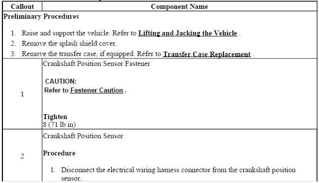
Crankshaft position sensor replacement
.gif)
Fig. 101: Crankshaft Position Sensor
Crankshaft Position Sensor Replacement

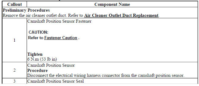
CAMSHAFT POSITION SENSOR REPLACEMENT
.gif)
Fig. 102: Camshaft Position Sensor
Camshaft Position Sensor Replacement
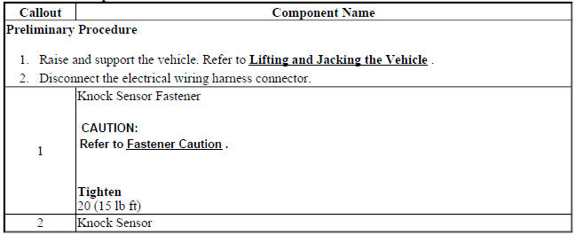
KNOCK SENSOR REPLACEMENT
.gif)
Fig. 103: Knock Sensor
Knock Sensor Replacement
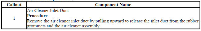
AIR CLEANER INLET DUCT REPLACEMENT
.gif)
Fig. 104: Air Cleaner Inlet Duct
Air Cleaner Inlet Duct Replacement
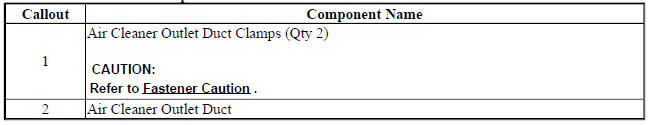
AIR CLEANER OUTLET DUCT REPLACEMENT
.gif)
Fig. 105: Air Cleaner Outlet Duct
Air Cleaner Outlet Duct Replacement
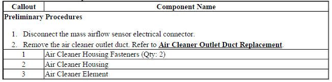
AIR CLEANER ELEMENT REPLACEMENT
.gif)
Fig. 106: Air Cleaner Element
Air Cleaner Element Replacement
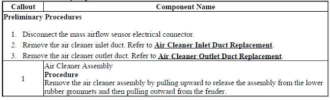
AIR CLEANER ASSEMBLY REPLACEMENT
.gif)
Fig. 107: Air Cleaner Assembly
Air Cleaner Assembly Replacement
CHARGE AIR COOLER REPLACEMENT
.gif)
Fig. 108: Charge Air Cooler
Charge Air Cooler Replacement
.jpg)
.jpg)
Charge air cooler inlet air hose replacement
Removal Procedure
- Remove the front bumper fascia. Refer to Front Bumper Fascia Replacement (Encore) , Front Bumper Fascia Replacement (Encore)
.gif)
Fig. 109: Charge Air Cooler Inlet Air Hose Clamp
- Loosen the charge air cooler inlet air pipe clamp (1) at the turbocharger outlet.
.gif)
Fig. 110: Charge Air Cooler Inlet Retainer Spring
- Unclip the retainer spring (1) at the charge air cooler inlet.
- Remove the charge air cooler inlet air hose (2) from the charge air cooler (3) and remove the hose from the vehicle.
Installation Procedure
.gif)
Fig. 111: Charge Air Cooler Inlet Retainer Spring
- Install the charge air cooler inlet air hose (2) to charge air cooler (3).
- Clip the in retainer spring (1).
.gif)
Fig. 112: Charge Air Cooler Inlet Air Hose Clamp
- Install the charge air cooler inlet air pipe to the turbocharger outlet.
CAUTION: Refer to Fastener Caution .
- Tighten the clamp (1).
- Install the front bumper fascia. Refer to Front Bumper Fascia Replacement (Encore) , Front Bumper Fascia Replacement (Encore) .
CHARGE AIR COOLER OUTLET AIR HOSE REPLACEMENT
Removal Procedure
- Remove the front bumper fascia. Refer to Front Bumper Fascia Replacement (Encore) , Front Bumper Fascia Replacement (Encore) .
- Disconnect the intake air pressure and temperature sensor electrical connector.
.gif)
Fig. 113: Charge Air Cooler Outlet Air Hose, Throttle Body & Clamp
- Loosen the clamp (1) at the charge air cooler outlet pipe (2) to throttle body (3).
.gif)
Fig. 114: Charge Air Cooler Outlet Air Pipe To Frame Bracket
- Remove the fasteners (1) from the charge air cooler outlet air pipe to frame bracket (2).
.gif)
Fig. 115: Charge Air Cooler, Outlet Air Hose & Retainer Spring
- Unclip the retainer spring (1).
- Remove the charge air cooler outlet air hose (2) from the charge air cooler (3).
Installation Procedure
.gif)
Fig. 116: Charge Air Cooler, Outlet Air Hose & Retainer Spring
- Install the charge air cooler outlet air hose (2) to charge air cooler (3).
- Clip the in retainer spring (1).
.gif)
Fig. 117: Charge Air Cooler Outlet Air Pipe To Frame Bracket
- Install the fasteners (1) to the charge air cooler outlet air pipe to frame bracket (2).
.gif)
Fig. 118: Charge Air Cooler Outlet Air Hose, Throttle Body & Clamp
- Install the charge air cooler inlet air pipe to the turbocharger.
CAUTION: Refer to Fastener Caution .
- Tighten the clamp (1).
- Connect the intake air pressure and temperature sensor electrical connector.
- Install the front bumper fascia. Refer to Front Bumper Fascia Replacement (Encore) , Front Bumper Fascia Replacement (Encore) .
CHARGE AIR BYPASS REGULATOR SOLENOID VALVE REPLACEMENT
.gif)
Fig. 119: Charge Air Bypass Regulator Solenoid Valve
Charge Air Bypass Regulator Solenoid Valve Replacement
.jpg)
READ NEXT:
 Schematic wiring diagrams
ENGINE CONTROLS WIRING SCHEMATICS (ENCORE)
Module Power, Ground, Serial Data, and MIL
Fig. 1: Module Power, Ground, Serial Data, and MIL
5V1, 5V2, and Low Reference Bus (1 of 2)
Fig. 2: 5V1, 5V2,
Schematic wiring diagrams
SPECIFICATIONS
TEMPERATURE VERSUS RESISTANCE
Temperature Versus Resistance
Fastener Tightening Specifications
SCHEMATIC WIRING DIAGRAMS
ENGINE HEATING/COOLING WIRING SCHEMATICS (ENCORE)
Engine C
SEE MORE:
Service programming system (SPS)
Special Tools
EL-49642 SPS Programming Support Tool
For equivalent regional tools, refer to Special Tools.
For step-by-step control module programming instructions, please refer to the
techline information system (TIS)
terminal.
Review the information below to ensure proper programming protocol.
N
Rear Vision Camera (RVC)
The RVC can assist when backing
up by displaying a view of the area
behind the vehicle.
Warning
The camera(s) do not display
children, pedestrians, bicyclists,
crossing traffic, animals, or any
other object outside of the
cameras' field of view, below the
bumper, or under the vehicle.
Shown distance
