Buick Encore: Schematic wiring diagrams
ENGINE CONTROLS WIRING SCHEMATICS (ENCORE)
Module Power, Ground, Serial Data, and MIL
.jpg)
Fig. 1: Module Power, Ground, Serial Data, and MIL
5V1, 5V2, and Low Reference Bus (1 of 2)
.jpg)
Fig. 2: 5V1, 5V2, and Low Reference Bus (1 of 2)
5V3, 5V4, and Low Reference Bus (2 of 2)
.jpg)
Fig. 3: 5V3, 5V4, and Low Reference Bus (2 of 2)
Engine Data Sensors - Pressure, and Temperature
.jpg)
Fig. 4: Engine Data Sensors - Pressure, and Temperature
Camshaft, Crankshaft, and Knock Sensors, Camshaft Actuators
.jpg)
Fig. 5: Camshaft, Crankshaft, and Knock Sensors, Camshaft Actuators
Engine Data Sensors - Throttle and Brake Sensor Controls
.jpg)
Fig. 6: Engine Data Sensors - Throttle and Brake Sensor Controls
Fuel Controls - Fuel Injectors and Ignition Controls
.jpg)
Fig. 7: Fuel Controls - Fuel Injectors and Ignition Controls
Engine Data Sensors - Oxygen Sensors
.jpg)
Fig. 8: Engine Data Sensors - Oxygen Sensors
Fuel Controls - Evaporative Emission and Device Controls
.jpg)
Fig. 9: Fuel Controls - Evaporative Emission and Device Controls
Fuel Controls - Fuel Pump and Fuel Pump Controls (LUV)
.jpg)
Fig. 10: Fuel Controls - Fuel Pump and Fuel Pump Controls (LUV)
Fuel Controls - Fuel Pump (LUJ)
.jpg)
Fig. 11: Fuel Controls - Fuel Pump (LUJ)
Controlled/Monitored Subsystem References
.jpg)
Fig. 12: Controlled/Monitored Subsystem References
ENGINE CONTROLS WIRING SCHEMATICS (Encore)
Module Power, Ground, Serial Data, and MIL
.jpg)
Fig. 13: Module Power, Ground, Serial Data, and MIL
5V1, 5V2, and Low Reference Bus (1 of 2)
.jpg)
Fig. 14: 5V1, 5V2, and Low Reference Bus (1 of 2)
5V3, 5V4, and Low Reference Bus (2 of 2)
.jpg)
Fig. 15: 5V3, 5V4, and Low Reference Bus (2 of 2)
Engine Data Sensors - Pressure, and Temperature
.jpg)
Fig. 16: Engine Data Sensors - Pressure, and Temperature
Camshaft, Crankshaft, and Knock Sensors, Camshaft Actuators
.jpg)
Fig. 17: Camshaft, Crankshaft, and Knock Sensors, Camshaft Actuators
Engine Data Sensors - Throttle and Brake Sensor Controls
.jpg)
Fig. 18: Engine Data Sensors - Throttle and Brake Sensor Controls
Fuel Controls - Fuel Injectors and Ignition Controls
.jpg)
Fig. 19: Fuel Controls - Fuel Injectors and Ignition Controls
Engine Data Sensors - Oxygen Sensors
.jpg)
Fig. 20: Engine Data Sensors - Oxygen Sensors
Fuel Controls - Evaporative Emission and Device Controls
.jpg)
Fig. 21: Fuel Controls - Evaporative Emission and Device Controls
Fuel Controls - Fuel Pump and Fuel Pump Controls (FHA)
.jpg)
Fig. 22: Fuel Controls - Fuel Pump and Fuel Pump Controls (FHA)
Fuel Controls - Fuel Pump (-FHA)
.jpg)
Fig. 23: Fuel Controls - Fuel Pump (-FHA)
Controlled/Monitored Subsystem References
.jpg)
Fig. 24: Controlled/Monitored Subsystem References
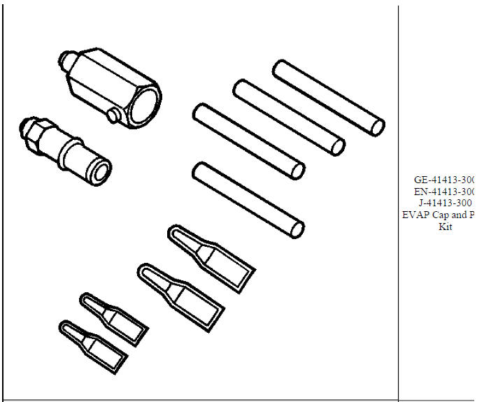
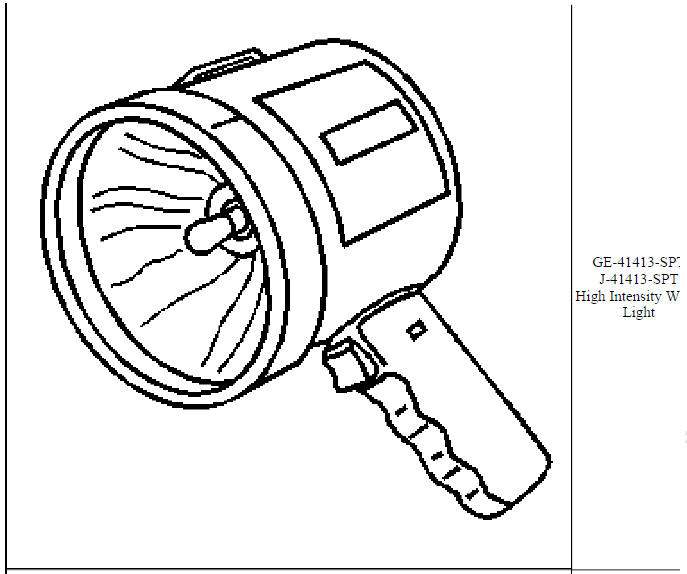
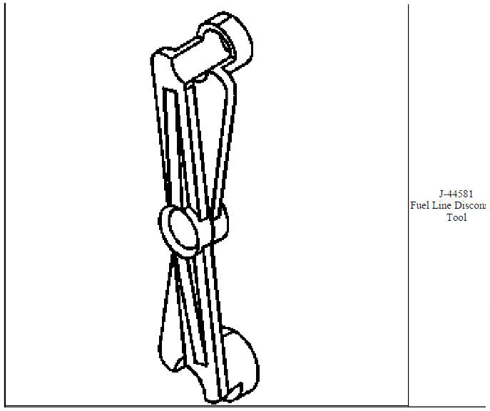
SPECIAL TOOLS AND EQUIPMENT
SPECIAL TOOLS (DIAGNOSTIC TOOLS)
.jpg)
.jpg)
.jpg)
.jpg)
.jpg)
.jpg)

.jpg)
.jpg)

.jpg)

.jpg)
.jpg)
.jpg)
.jpg)
.jpg)
.jpg)
.jpg)
.jpg)
.jpg)
.jpg)
.jpg)
.jpg)
.jpg)
.jpg)
.jpg)
.jpg)
.jpg)
.jpg)
.jpg)
.jpg)
.jpg)
.jpg)
.jpg)
.jpg)
.jpg)
.jpg)
.jpg)
.jpg)
.jpg)
.jpg)


.jpg)
.jpg)
SPECIFICATIONS
Temperature Versus Resistance
.jpg)
Temperature Versus Resistance - Intake Air Temperature Sensor (Bosch Sensor)
.jpg)
.jpg)
Temperature Versus Resistance - Intake Air Temperature Sensor (Delco Sensor)
.jpg)
Altitude Versus Barometric Pressure
.jpg)
.jpg)
Ignition System Specifications
.jpg)
Fastener Tightening Specifications
.jpg)
.jpg)
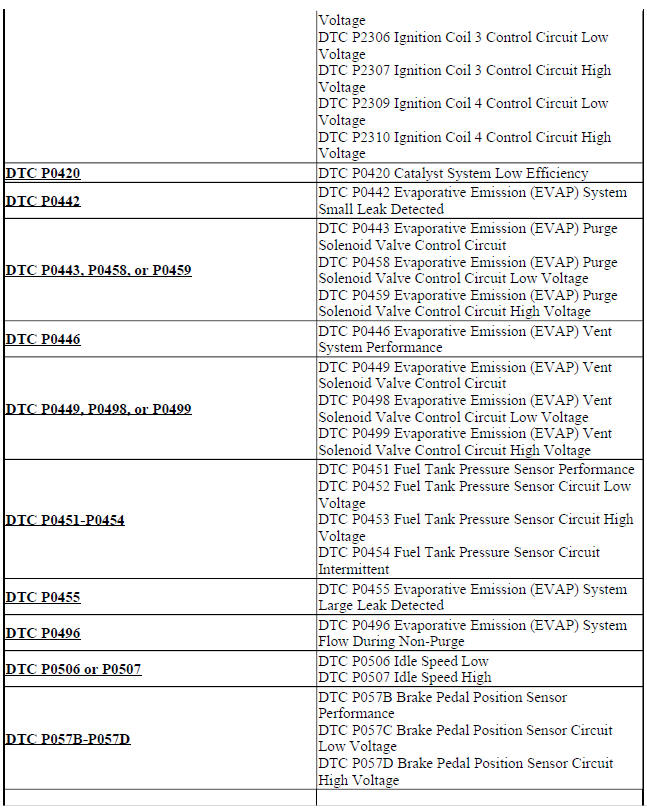
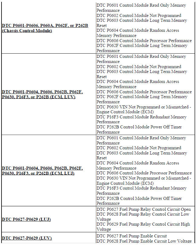
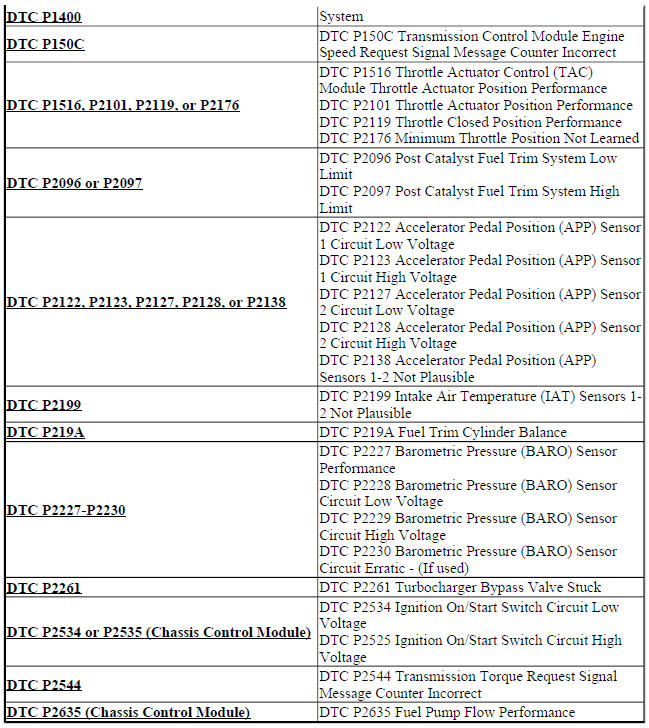
DIAGNOSTIC CODE INDEX
.jpg)
.jpg)
.jpg)


READ NEXT:
 Schematic wiring diagrams
SPECIFICATIONS
TEMPERATURE VERSUS RESISTANCE
Temperature Versus Resistance
Fastener Tightening Specifications
SCHEMATIC WIRING DIAGRAMS
ENGINE HEATING/COOLING WIRING SCHEMATICS (ENCORE)
Engine C
Engine Heating and Cooling - Diagnostic information and procedures
DTC P00B3 OR P00B4 (2H0 OR LUJ): Radiator coolant temperature (RCT) sensor
DIAGNOSTIC CODE INDEX
Diagnostic Instructions
Perform the Diagnostic System Check - Vehicle prior to using this
diagn
SEE MORE:
Immobilizer - Repair instructions
THEFT DETERRENT MODULE REPLACEMENT (ENCORE)
Fig. 3: Theft Deterrent Module (Encore)
Theft Deterrent Module Replacement (Encore)
THEFT DETERRENT MODULE REPLACEMENT (Encore)
Fig. 4: Theft Deterrent Module
Theft Deterrent Module Replacement (Encore)
IMMOBILIZER SYSTEM COMPONENT PROGRAMMING
This
Dangers, Warnings, and Cautions
INTRODUCTION
Definition of danger, warning, caution, and note
The diagnosis and repair procedures in a GM Service Manual contain both
general and specific Dangers,
Warnings, Cautions, Notes or Importants. GM is dedicated to the presentation of
service information that helps
the technician to diagn
