Buick Encore: Horns - Description and operation
HORNS SYSTEM DESCRIPTION AND OPERATION
System Description
The horn system consists of the following components:
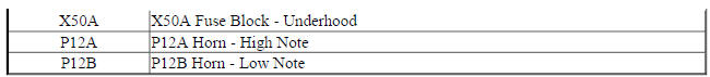
- HORN fuse
- Underhood fuse block (contains PCB horn relay)
- Horn switch
- Horn-low note
- Horn-high note
- Body control module (BCM)
14 Horns Block Diagram
Fig. 6: 14 Horns Block Diagram

System Operation
The vehicle horn system is activated under the following conditions:
- When the horn switch is depressed
- The BCM commands the horns ON under any of the following conditions:
- When the content theft deterrent system detects a vehicle intrusion-For further information refer to Theft Systems Description and Operation .
- When the panic button is depressed on the remote control door lock transmitter-For further information refer to Keyless Entry System Description and Operation .
- When the keyless entry system is used to lock the vehicle, a horn chirp may sound to notify the driver that the vehicle has been locked. The notification feature may be enabled or disabled through personalization. For further information refer to Keyless Entry System Description and Operation .
- When the OnStar system is used to sound the horns if equipped-For further information, refer to OnStar Description and Operation
Circuit Operation
Battery positive voltage is applied at all times to the horn relay coil and the horn relay switch. Pressing either of the horn switches applies ground to the horn relay control circuit. The BCM may also apply ground to the horn relay control circuit as described above. When the horn relay control circuit is grounded, the horn relay is energized and battery positive voltage is applied to the horns through the horn control circuit. The horns sound as long as ground is applied to the horn relay control circuit.
READ NEXT:
 Immobilizer
Schematic wiring diagrams
IMMOBILIZER WIRING SCHEMATICS (ENCORE)
Immobilzer System
Fig. 1: Immobilzer System
IMMOBILIZER WIRING SCHEMATICS (Encore)
Immobilzer System
Fig. 2: Immobilzer System
Immobilizer - Diagnostic information and procedures
DTC B2955: Security sensor data circuit
DIAGNOSTIC CODE INDEX
DTC B2955: SECURITY SENSOR DATA CIRCUIT
Diagnostic Instructions
Perform the Diagnostic System Check - Vehicle prior to using this
Immobilizer - Repair instructions
THEFT DETERRENT MODULE REPLACEMENT (ENCORE)
Fig. 3: Theft Deterrent Module (Encore)
Theft Deterrent Module Replacement (Encore)
THEFT DETERRENT MODULE REPLACEMENT (Encore)
Fig. 4: Theft Deterren
SEE MORE:
Shifting out of Park
This vehicle is equipped with a shift
lock control. The shift lock control is
designed to prevent movement of
the shift lever out of P (Park) unless
the ignition is on and the brake
pedal is applied.
The shift lock control is always
functional except in the case of an
uncharged or low voltage (less
Lock cylinder coding - ignition
Fig. 14: Lock Cylinder Components - Ignition
The ignition lock cylinder uses 8 key cut positions, 1-8. The ignition
cylinder tumblers (3) are located on alternate sides of the cylinder (5). They
are not snap-in and are not self-retaining. It follows the key code with
the first tumbler being the
