Buick Encore: Lighting - Diagnostic information and procedures
DTC B1480
Diagnostic Instructions
- Perform the Diagnostic System Check - Vehicle prior to using this diagnostic procedure.
- Review Strategy Based Diagnosis for an overview of the diagnostic approach.
- Diagnostic Procedure Instructions provides an overview of each diagnostic category.
DTC Descriptor
DTC B1480 02
Battery Rundown Protection Circuit Short to Ground
Diagnostic Fault Information
.jpg)
Circuit/System Description
The body control module (BCM) supplies battery voltage to the reading lamps and sunshade mirror lamps via the courtesy lamp control circuit. The front reading lamps are controlled by an individual switch that is activated by the operator when additional cabin lighting is required. In the event that the reading lamps or sunshade lamps were to remain illuminated for more than 10 minutes with the ignition switch in the OFF position and no doors opened, the BCM will deactivate the courtesy lamp control circuit to prevent total battery discharge.
Conditions for Running the DTC
Battery voltage must be between 9-16 V.
Conditions for Setting the DTC
The BCM detects a short to ground in the courtesy lamps control circuit terminal 2 X7.
Actions Taken When the DTC Sets
The BCM will disable the circuit and the reading/sunshade lamps will be inoperative.
Conditions for Clearing the DTC
- The condition responsible for setting the DTC no longer exists.
- A history DTC will clear once 100 consecutive malfunction-free ignition cycles have occurred.
Reference Information
Schematic Reference
- Interior Lights Schematics (Encore) , Interior Lights Schematics (Encore)
- Body Control System Schematics (Encore) , Body Control System Schematics (Encore)
Connector End View Reference
WIRING SYSTEMS AND POWER MANAGEMENT - COMPONENT CONNECTOR END VIEWS - INDEX - ENCORE WIRING SYSTEMS AND POWER MANAGEMENT - COMPONENT CONNECTOR END VIEWS - INDEX - Encore
Description and Operation
Interior Lighting Systems Description and Operation
Electrical Information Reference
- Circuit Testing
- Connector Repairs
- Testing for Intermittent Conditions and Poor Connections
- Wiring Repairs
Scan Tool Reference
Control Module References for scan tool information
Circuit/System Testing
- Ignition OFF, exterior lamps OFF, disconnect the harness connectors at the components listed below.
- E37A Dome/Reading Lamps
- E36AH Dome Lamp
- A3L Sunshade - Left
- A3R Sunshade - Right
- Connect a test lamp between the appropriate control circuit terminal listed below and ground.
- E37A Dome/Reading Lamps - terminal 1
- E36AH Dome Lamp - terminal 4
- A3L Sunshade - Left terminal A
- A3R Sunshade - Right terminal A
- Verify the test lamp turns ON and OFF when commanding the Inadvertent Load ON and OFF with a scan tool.
- If the test lamp is always OFF
- Ignition OFF, disconnect the X7 harness connector at the K9 Body Control Module.
- Test for infinite resistance between the control circuit and ground.
- If less than infinite resistance, repair the short to ground on the circuit.
- If infinite resistance
- Test for less than 2 ohms in the control circuit end to end.
- If 2 ohms or greater, repair the open/high resistance in the circuit.
- If less than 2 ohms, replace the K9 Body Control Module.
- If the test lamp is always ON
- Ignition OFF, disconnect the X7 harness connector at the K9 Body Control Module, ignition ON.
- Test for less than 1 V between the control circuit terminal and ground.
- If 1 V or greater, repair the short to voltage on the circuit.
- If less than 1 V, replace the K9 Body Control Module.
- If the test lamp turns ON and OFF
- Test or replace the inoperative courtesy lamp.
Repair Instructions
Perform the Diagnostic Repair Verification after completing the repair.
- Dome Lamp Bulb Replacement
- Center Reading Lamp Replacement
- Center Reading Lamp Bulb Replacement
- Control Module References for BCM replacement, programming, and setup
DTC B2530
Diagnostic Instructions
- Perform the Diagnostic System Check - Vehicle prior to using this diagnostic procedure.
- Review Strategy Based Diagnosis for an overview of the diagnostic approach.
- Diagnostic Procedure Instructions provides an overview of each diagnostic category.
DTC Descriptors
DTC B2530 01
Front Fog Lamps Control Circuit Short to Battery
DTC B2530 02
Front Fog Lamps Control Circuit Short to Ground
DTC B2530 04
Front Fog Lamps Control Circuit Open
Diagnostic Fault Information
.jpg)
Circuit/System Description
The front fog lamp switch is an input to the body control module (BCM) and is contained in the headlamp switch assembly. The BCM supplies voltage to the front fog lamp switch via the front fog lamp and instrument panel dimmer switch B+ circuit. When the front fog lamp switch is pressed, voltage from the B+ circuit is pulled down through the front fog lamp switch resistor. The front fog lamp resistor is part of the resistor ladder that also provides the dimming signals for the instrument panel dimmer switches. The BCM receives the voltage signal through the front fog lamp and instrument panel dimmer switch signal circuit.
The front fog lamp relay is supplied with battery voltage at all times. The front fog lamp switch signal circuit is grounded momentarily by pressing the front fog lamp switch. The body control module (BCM) energizes the front fog lamp relay by applying ground to the front fog lamp relay control circuit. When the front fog lamp relay is energized, the relay switch contacts close and battery voltage is applied through the front fog lamp fuse to the front fog lamp control circuit which illuminates the front fog lamps.
Conditions for Running the DTC
- Battery voltage must be between 9-16 V.
- Front fog lamps ON.
Conditions for Setting the DTC
DTC B2530 01
The BCM detects a short to voltage in the front fog lamp relay control circuit for 5 seconds or greater.
DTC B2530 02
The BCM detects a short to ground in the front fog lamp relay control circuit.
DTC B2530 04
The BCM detects an open in the front fog lamp relay control circuit.
Actions Taken When the DTC Sets
DTC B2530 01 and B2530 04
The front fog lamps will not operate when the park lamps are ON and the front fog lamp switch is active.
DTC B2530 02
The front fog lamps always ON.
Conditions for Clearing the DTC
- The condition responsible for setting the DTC no longer exists.
- A history DTC will clear once 100 consecutive malfunction-free ignition cycles have occurred.
Reference Information
Schematic Reference
Fog Lights Schematics (Encore) , Fog Lights Schematics (Encore)
Connector End View Reference
WIRING SYSTEMS AND POWER MANAGEMENT - COMPONENT CONNECTOR END VIEWS - INDEX - ENCORE WIRING SYSTEMS AND POWER MANAGEMENT - COMPONENT CONNECTOR END VIEWS - INDEX - Encore
Description and Operation
Exterior Lighting Systems Description and Operation
Electrical Information Reference
- Circuit Testing
- Connector Repairs
- Testing for Intermittent Conditions and Poor Connections
- Wiring Repairs
Scan Tool Reference
Control Module References for scan tool information
Circuit/System Testing
- Ignition OFF, disconnect the X5 harness connector at the K9 Body Control Module, ignition ON.
- Verify a test lamp illuminates between the control circuit terminal 13 and ground.
If the test lamp does not illuminate
- Ignition OFF, disconnect the X2 harness connector at the X50A Fuse Block - Underhood.
- Test for infinite resistance between the control circuit terminal and ground.
- If less than infinite resistance, repair the short to ground on the circuit.
- If infinite resistance
- Test for less than 2 ohms in the control circuit end to end.
- If 2 ohms or greater, repair the open/high resistance in the circuit.
- If less than 2 ohms, replace the X50A Fuse Block - Underhood.
- If the test lamp illuminates
- Ignition OFF, connect a 3 A fused jumper between the control circuit terminal 13 and ground.
- Remove the front fog lamp fuse at the X50A Fuse Block - Underhood, ignition ON.
- Verify a test lamp illuminates between the front fog lamp fuse B+ switch control terminal and ground.
- If the test lamp does not illuminate
- Ignition OFF, disconnect the X2 harness connector at the X50A Fuse Block - Underhood, ignition ON.
- Test for less than 1 V between the control circuit terminal 13 and ground.
- If 1 V or greater, repair the short to voltage on the circuit.
- If less than 1 V, replace the X50A Fuse Block - Underhood
If the test lamp illuminates
- Test or replace the K9 Body Control Module.
Repair Instructions
Perform the Diagnostic Repair Verification after completing the repair.
- Front Compartment Fuse Block Replacement
- Control Module References for BCM replacement, programming, and setup
DTC B2545
Diagnostic Instructions
- Perform the Diagnostic System Check - Vehicle prior to using this diagnostic procedure.
- Review Strategy Based Diagnosis for an overview of the diagnostic approach.
- Diagnostic Procedure Instructions provides an overview of each diagnostic category.
DTC Descriptors
DTC B2545 01
Backup Lamps Circuit Short to Battery
DTC B2545 02
Backup Lamps Circuit Short to Ground
DTC B2545 04
Backup Lamps Circuit Open
Diagnostic Fault Information
.jpg)
.jpg)
Circuit/System Description
Automatic Transmission
With the engine running and the transmission in the reverse position, the transmission control module (TCM) sends a serial data message to the body control module (BCM). The message indicates that the gear selector is in the reverse position. The BCM applies battery voltage to the backup lamps control circuit illuminating the backup lamps. Once the driver moves the gear selector out of the reverse position, a message is sent by the TCM via serial data requesting the BCM to remove battery voltage from the backup lamps control circuit. The engine must be running for the backup lamps to operate.
Manual Transmission
The engine control module (ECM) provides a signal circuit to the backup lamp switch which is permanently grounded. With the ignition ON and the transmission in the reverse position, the backup lamp switch signal circuit is pulled low and the ECM responds by sending a serial data message to the body control module (BCM). The message indicates that the gear selector is in the reverse position. The BCM applies battery voltage to the backup lamps control circuit illuminating the backup lamps. Once the driver moves the gear selector out of the reverse position, a message is sent by the ECM via serial data requesting the BCM to remove battery voltage from the backup lamps control circuit.
Conditions for Running the DTC
- Battery voltage must be between 9-16 V.
- Engine RUNNING.
- Transmission placed in REVERSE gear.
Conditions for Setting the DTC
DTC B2545 01
The BCM detects a short to voltage in the backup lamps control circuit.
DTC B2545 02
The BCM detects a short to ground in the backup lamps control circuit.
DTC B2545 04
The BCM detects an open/high resistance in the backup lamps control circuit.
Actions Taken When the DTC Sets
DTC B2545 02 and B2545 04
The backup lamps will not operate.
DTC B2545 01
The backup lamps are always ON.
Conditions for Clearing the DTC
- The condition responsible for setting the DTC no longer exists.
A history DTC will clear once 100 consecutive malfunction-free ignition cycles have occurred.
Reference Information
Schematic Reference
- Exterior Lights Schematics (Encore) , Exterior Lights Schematics (Encore)
- Body Control System Schematics (Encore) , Body Control System Schematics (Encore)
Connector End View Reference
WIRING SYSTEMS AND POWER MANAGEMENT - COMPONENT CONNECTOR END VIEWS - INDEX - ENCORE WIRING SYSTEMS AND POWER MANAGEMENT - COMPONENT CONNECTOR END VIEWS - INDEX - Encore
Description and Operation
Exterior Lighting Systems Description and Operation
Electrical Information Reference
- Circuit Testing
- Connector Repairs
- Testing for Intermittent Conditions and Poor Connections
- Wiring Repairs
Scan Tool Reference
Control Module References for scan tool information
Circuit/System Testing
- Ignition OFF, exterior lamps OFF, rear hatch latch latched, remove the appropriate E5 Backup Lamp bulb at the appropriate E42 Tail Lamp Assembly.
- Test for less than 5 ohms between the ground circuit at the socket terminal and ground.
- If 5 ohms or greater
- Ignition OFF.
- Test for less than 2 ohms in the ground circuit end to end.
- If 2 ohms or greater, repair the open/high resistance in the circuit.
- If less than 2 ohms, repair the open/high resistance in the ground connection.
- If less than 5 ohms
- Connect a test lamp between the control circuit at the socket terminal and ground, ignition ON.
- Verify the test lamp turns ON and OFF when commanding the Backup Lamps ON and OFF with a scan tool.
- If the test lamp is always OFF
- Ignition OFF, disconnect the X7 harness connector at the K9 Body Control Module.
- Test for infinite resistance between the control circuit and ground.
- If less than infinite resistance, repair the short to ground on the circuit.
- If infinite resistance
- Test for less than 2 ohms in the control circuit end to end.
- If 2 ohms or greater, repair the open/high resistance in the circuit.
- If less than 2 ohms, replace the K9 Body Control Module.
- If the test lamp is always ON
- Ignition OFF, disconnect the X7 harness connector at the K9 Body Control Module, ignition ON.
- Test for less than 1 V between the control circuit terminal and ground.
- If 1 V or greater, repair the short to voltage on the circuit.
- If less than 1 V, replace the K9 Body Control Module.
- If the test lamp turns ON and OFF
- Test or replace the appropriate E5 Backup Lamp.
Repair Instructions
Perform the Diagnostic Repair Verification after completing the repair.
- Backup Lamp Bulb Replacement (Encore) , Backup Lamp Bulb Replacement (Encore)
- Control Module References for BCM replacement, programming, and setup
DTC B2570
Diagnostic Instructions
- Perform the Diagnostic System Check - Vehicle prior to using this diagnostic procedure.
- Review Strategy Based Diagnosis for an overview of the diagnostic approach.
- Diagnostic Procedure Instructions provides an overview of each diagnostic category.
DTC Descriptor
DTC B2570 02
Rear Compartment Courtesy Lamp Control Circuit Short to Ground
Diagnostic Fault Information
.jpg)
Circuit/System Description
The body control module (BCM) applies battery voltage to the rear compartment courtesy lamp through the rear compartment lamp control circuit. When the BCM receives a rear compartment lid open input from the rear compartment lid latch, the BCM applies battery voltage to the rear compartment lamp control circuit illuminating the rear compartment courtesy lamp. In the event that the rear compartment lamp were to remain illuminated for more than 10 minutes with the ignition switch in the OFF position and no doors opened, the BCM will deactivate the rear compartment lamp control circuit to prevent total battery discharge.
Conditions for Running the DTC
- Battery voltage must be between 9-16 V.
- Rear compartment OPEN.
Conditions for Setting the DTC
The BCM detects a short to ground on the rear compartment courtesy lamp control circuit.
Actions Taken When the DTC Sets
The rear compartment lamp is inoperative.
Conditions for Clearing the DTC
- The condition responsible for setting the DTC no longer exists.
- A history DTC will clear once 100 consecutive malfunction-free ignition cycles have occurred.
Reference Information
Schematic Reference
Interior Lights Schematics (Encore) , Interior Lights Schematics (Encore)
Connector End View Reference
WIRING SYSTEMS AND POWER MANAGEMENT - COMPONENT CONNECTOR END VIEWS - INDEX - ENCORE WIRING SYSTEMS AND POWER MANAGEMENT - COMPONENT CONNECTOR END VIEWS - INDEX - Encore
Description and Operation
Interior Lighting Systems Description and Operation
Electrical Information Reference
- Circuit Testing
- Connector Repairs
- Testing for Intermittent Conditions and Poor Connections
- Wiring Repairs
Scan Tool Reference
Control Module References for scan tool information
Circuit/System Testing
- Ignition OFF, exterior lamps OFF, rear hatch latch latched, disconnect the harness connector at the E8S Rear Compartment Courtesy Lamp.
- Test for less than 5 ohms between the ground circuit terminal 2 and ground.
- If 5 ohms or greater
- Ignition OFF.
- Test for less than 2 ohms in the ground circuit end to end.
- If 2 ohms or greater, repair the open/high resistance in the circuit.
- If less than 2 ohms, repair the open/high resistance in the ground connection.
- If less than 5 ohms
- Connect a test lamp between the control circuit terminal 1 and ground, ignition ON.
- Verify the test lamp turns ON and OFF when commanding the Cargo Lamp ON and OFF with a scan tool.
- If the test lamp is always OFF
- Ignition OFF, disconnect the X7 harness connector at the K9 Body Control Module.
- Test for infinite resistance between the control circuit and ground.
- If less than infinite resistance, repair the short to ground on the circuit.
- If infinite resistance
- Test for less than 2 ohms in the control circuit end to end.
- If 2 ohms or greater, repair the open/high resistance in the circuit.
- If less than 2 ohms, replace the K9 Body Control Module.
- If the test lamp is always ON
- Ignition OFF, disconnect the X7 harness connector at the K9 Body Control Module, ignition ON.
- Test for less than 1 V between the control circuit terminal and ground.
- If 1 V or greater, repair the short to voltage on the circuit.
- If less than 1 V, replace the K9 Body Control Module.
- If the test lamp turns ON and OFF
- Test or replace the E8S Rear Compartment Courtesy Lamp.
Repair Instructions
Perform the Diagnostic Repair Verification after completing the repair.
- Cargo Lamp Replacement
- Cargo Center Courtesy Lamp Bulb Replacement
- Control Module References for BCM replacement, programming, and setup
DTC B2575 OR B2699
Diagnostic Instructions
- Perform the Diagnostic System Check - Vehicle prior to using this diagnostic procedure.
- Review Strategy Based Diagnosis for an overview of the diagnostic approach.
- Diagnostic Procedure Instructions provides an overview of each diagnostic category.
DTC Descriptors
DTC B2575 01
Headlamps Control Circuit Short to Battery
DTC B2575 02
Headlamps Control Circuit Short to Ground
DTC B2575 04
Headlamps Control Circuit Open
DTC B2699 01
Right Headlamp Control Circuit Short to Battery
DTC B2699 02
Right Headlamp Control Circuit Short to Ground
DTC B2699 04
Right Headlamp Control Circuit Open
Diagnostic Fault Information
.jpg)
Circuit/System Description
With the headlamp switch in the ON position, the headlamp switch headlamp ON signal circuit is grounded through the headlamp switch. The body control module (BCM) responds by applying battery positive voltage to the left and right low beam headlamp control circuits illuminating the low beam headlamps.
Conditions for Running the DTC
- Battery voltage must be between 9-16 V.
- Low beam headlamps ON.
Conditions for Setting the DTC
DTC B2575 01 and B2575 04
- The BCM detects a short to voltage or an open/high resistance in the left low beam headlamp control circuit.
- The BCM detects a short to ground or an open/high resistance in the F4DA (BCM 4) fuse B+ circuit.
DTC B2575 02
The BCM detects a short to ground in the left low beam headlamp control circuit.
DTC B2699 01 and B2699 04
- The BCM detects a short to voltage or an open/high resistance in the right low beam headlamp control circuit.
- The BCM detects a short to ground or an open/high resistance in the F3DA (BCM 3) fuse B+ circuit
DTC B2699 02
The BCM detects a short to ground in the right low beam headlamp control circuit.
Actions Taken When the DTC Sets
- When DTC B2575 sets, the left low beam headlamp will be inoperative.
- When DTC B2699 sets, the right low beam headlamp will be inoperative
Conditions for Clearing the DTC
- The condition responsible for setting the DTC no longer exists.
- A history DTC will clear once 100 consecutive malfunction-free ignition cycles have occurred.
Reference Information
Schematic Reference
- Headlights/Daytime Running Lights (DRL) Schematics (Encore) , Headlights/Daytime Running Lights (DRL) Schematics (Encore)
- Body Control System Schematics (Encore) , Body Control System Schematics (Encore)
Connector End View Reference
WIRING SYSTEMS AND POWER MANAGEMENT - COMPONENT CONNECTOR END VIEWS - INDEX - ENCORE WIRING SYSTEMS AND POWER MANAGEMENT - COMPONENT CONNECTOR END VIEWS - INDEX - Encore
Description and Operation
Exterior Lighting Systems Description and Operation
Electrical Information Reference
- Circuit Testing
- Connector Repairs
- Testing for Intermittent Conditions and Poor Connections
- Wiring Repairs
Scan Tool Reference
Control Module References for scan tool information
Circuit/System Testing
DTC B2575
- Ignition OFF, disconnect the X1 harness connector at the K9 Body Control Module, ignition ON.
- Verify a test lamp illuminates between the B+ circuit terminal 2 and ground.
- If the test lamp does not illuminate and the circuit fuse is good
- Ignition OFF.
- Test for less than 2 ohms in the B+ circuit end to end.
- If 2 ohms or greater, repair the open/high resistance in the circuit.
- If less than 2 ohms, verify the fuse is not open and there is voltage at the fuse.
- If the test lamp does not illuminate and the circuit fuse is open
- Ignition OFF.
- Test for infinite resistance between the B+ circuit and ground.
- If less than infinite resistance, repair the short to ground on the circuit.
- If infinite resistance, replace the K9 Body Control Module.
- If the test lamp illuminates
- Ignition OFF, connect the X1 harness connector at the K9 Body Control Module.
- Ignition OFF, exterior lamps OFF, disconnect the harness connector at the E13L Headlamp - Left.
- Test for less than 5 ohms between the ground circuit terminal C and ground.
- If 5 ohms or greater
- Ignition OFF.
- Test for less than 2 ohms in the ground circuit end to end.
- If 2 ohms or greater, repair the open/high resistance in the circuit.
- If less than 2 ohms, repair the open/high resistance in the ground connection.
- If less than 5 ohms
- Connect a test lamp between the control circuit terminal A and ground, ignition ON.
- Verify the test lamp turns ON and OFF when commanding the Left Low Beam/Daytime Running Lamp ON and OFF with a scan tool.
- If the test lamp is always OFF
- Ignition OFF, disconnect the X4 harness connector at the K9 Body Control Module.
- Test for infinite resistance between the control circuit and ground.
- If less than infinite resistance, repair the short to ground on the circuit.
- If infinite resistance
- Test for less than 2 ohms in the control circuit end to end.
- If 2 ohms or greater, repair the open/high resistance in the circuit.
- If less than 2 ohms, replace the K9 Body Control Module.
- If the test lamp is always ON
- Ignition OFF, disconnect the X4 harness connector at the K9 Body Control Module, ignition ON.
- Test for less than 1 V between the control circuit terminal and ground.
- If 1 V or greater, repair the short to voltage on the circuit.
- If less than 1 V, replace the K9 Body Control Module.
- If the test lamp turns ON and OFF
- Test or replace the E13L Headlamp Bulb - Left.
DTC B2699
- Ignition OFF, disconnect the X1 harness connector at the K9 Body Control Module, ignition ON.
- Verify a test lamp illuminates between the B+ circuit terminal 3 and ground.
- If the test lamp does not illuminate and the circuit fuse is good
- Ignition OFF.
- Test for less than 2 ohms in the B+ circuit end to end.
- If 2 ohms or greater, repair the open/high resistance in the circuit.
- If less than 2 ohms, verify the fuse is not open and there is voltage at the fuse.
- If the test lamp does not illuminate and the circuit fuse is open
- Ignition OFF.
- Test for infinite resistance between the B+ circuit and ground.
- If less than infinite resistance, repair the short to ground on the circuit.
- If infinite resistance, replace the K9 Body Control Module.
- If the test lamp illuminates
- Ignition OFF, connect the X1 harness connector at the K9 Body Control Module.
- Ignition OFF, exterior lamps OFF, disconnect the harness connector at the E13R Headlamp - Right.
- Test for less than 5 ohms between the ground circuit terminal C and ground.
- If 5 ohms or greater
- Ignition OFF.
- Test for less than 2 ohms in the ground circuit end to end.
- If 2 ohms or greater, repair the open/high resistance in the circuit.
- If less than 2 ohms, repair the open/high resistance in the ground connection.
- If less than 5 ohms
- Connect a test lamp between the control circuit terminal A and ground, ignition ON.
- Verify the test lamp turns ON and OFF when commanding the Right Low Beam/Daytime Running Lamp ON and OFF with a scan tool.
- If the test lamp is always OFF
- Ignition OFF, disconnect the X4 harness connector at the K9 Body Control Module.
- Test for infinite resistance between the control circuit and ground.
- If less than infinite resistance, repair the short to ground on the circuit.
- If infinite resistance
- Test for less than 2 ohms in the control circuit end to end.
- If 2 ohms or greater, repair the open/high resistance in the circuit.
- If less than 2 ohms, replace the K9 Body Control Module.
- If the test lamp is always ON
- Ignition OFF, disconnect the X4 harness connector at the K9 Body Control Module, ignition ON.
- Test for less than 1 V between the control circuit terminal and ground.
- If 1 V or greater, repair the short to voltage on the circuit.
- If less than 1 V, replace the K9 Body Control Module.
- If the test lamp turns ON and OFF
- Test or replace the E13R Headlamp Bulb - Right.
Repair Instructions
Perform the Diagnostic Repair Verification after completing the repair.
- Headlamp Bulb Replacement - Left Side (Encore High Beam) , Headlamp Bulb Replacement - Left Side (Encore Low Beam)
- Headlamp Bulb Replacement - Right Side (High Beam) , Headlamp Bulb Replacement - Right Side (Low Beam)
- Control Module References for BCM replacement, programming, and setup
DTC B257A
Diagnostic Instructions
- Perform the Diagnostic System Check - Vehicle prior to using this diagnostic procedure.
- Review Strategy Based Diagnosis for an overview of the diagnostic approach.
- Diagnostic Procedure Instructions provides an overview of each diagnostic category.
DTC Descriptor
DTC B257A 00
Headlamp Switch Input Signals Correlation Malfunction
Diagnostic Fault Information
.jpg)
Circuit/System Description
For headlamp operation, the body control module (BCM) monitors three signal circuits from the headlamp switch. When the headlamp switch is in the AUTO position, the three signal circuits are unaffected and the BCM relies on the ambient light sensor input to turn the headlamps and daytime running lamps ON and OFF.
When the headlamp switch is placed in the OFF position, the headlamp switch headlamps OFF signal circuit is grounded, indicating to the BCM that the exterior lamps should be turned OFF. With the headlamp switch in the PARK LAMPS position, the headlamp switch park lamps ON signal circuit is grounded, indicating that the park lamps have been requested. When the headlamp switch is in the HEADLAMP position, both the headlamp switch park lamps ON signal circuit and the headlamp switch headlamps ON signal circuit are grounded. The BCM responds by commanding the park lamps and headlamps ON.
Conditions for Running the DTC
Battery voltage must be between 9-16 V.
Conditions for Setting the DTC
- The BCM detects an open/high resistance in the headlamp switch park lamps ON signal circuit.
- The BCM detects a short to ground in the headlamp switch headlamps ON signal circuit.
- The BCM detects a short to ground in the headlamp switch headlamps OFF signal circuit.
Actions Taken When the DTC Sets
- When DTC B257A 00 is present on the headlamp switch headlamps OFF signal circuit, the low beam headlamps are always ON in the AUTO position. The headlamp switch operates in all positions other than AUTO. The AUTO headlamp defeat is inoperative.
- When DTC B257A 00 is present on the headlamp switch headlamps ON signal circuit, the low beam headlamps are always ON. The BCM disregards all headlamp switch inputs.
- When DTC B257A 00 is present on the headlamp switch park lamps ON signal circuit, the park lamps and low beam headlamps are inoperative in the PARK and HEAD positions. Headlamps and park lamps operate in AUTO position.
Conditions for Clearing the DTC
- The condition responsible for setting the DTC no longer exists.
- A history DTC will clear once 100 consecutive malfunction-free ignition cycles have occurred.
Reference Information
Schematic Reference
Headlights/Daytime Running Lights (DRL) Schematics (Encore) , Headlights/Daytime Running Lights (DRL) Schematics (Encore)
Connector End View Reference
WIRING SYSTEMS AND POWER MANAGEMENT - COMPONENT CONNECTOR END VIEWS - INDEX - ENCORE WIRING SYSTEMS AND POWER MANAGEMENT - COMPONENT CONNECTOR END VIEWS - INDEX - Encore
Description and Operation
Exterior Lighting Systems Description and Operation
Electrical Information Reference
- Circuit Testing
- Connector Repairs
- Testing for Intermittent Conditions and Poor Connections
- Wiring Repairs
Scan Tool Reference
Control Module References for scan tool information
Circuit/System Testing
- Ignition OFF, all doors closed, all accessories OFF, disconnect the harness connector at the S30 Headlamp Switch. It may take up to 2 min for all vehicle systems to power down.
- Test for less than 15 ohms between the ground circuit terminal 6 and ground.
- If 15 ohms or greater
- Ignition OFF.
- Test for less than 2 ohms in the ground circuit end to end.
- If 2 ohms or greater, repair the open/high resistance in the circuit.
- If less than 2 ohms, repair the open/high resistance in the ground connection.
- If less than 15 ohms
- Ignition ON.
- Verify the scan tool Automatic Headlamps Disable Switch parameter is Inactive.
- If not Inactive
- Ignition OFF, disconnect the X1 harness connector at the K9 Body Control Module.
- Test for infinite resistance between the signal circuit terminal 5 and ground.
- If less than infinite resistance, repair the short to ground on the circuit.
- If infinite resistance, replace the K9 Body Control Module.
- If Inactive
- Install a 3 A fused jumper wire between the signal circuit terminal 5 and the ground circuit terminal 6.
- Verify the scan tool Automatic Headlamps Disable Switch parameter is Active.
If not Active
- Ignition OFF, disconnect the X1 harness connector at the K9 Body Control Module, ignition ON.
- Test for less than 1 V between the signal circuit terminal 5 and ground.
- If 1 V or greater, repair the short to voltage on the circuit.
- If less than 1 V
- Test for less than 2 ohms in the signal circuit end to end.
- If 2 ohms or greater, repair the open/high resistance in the circuit.
- If less than 2 ohms, replace the K9 Body Control Module.
- If Active
- Verify the scan tool Park Lamps Switch parameter is Inactive.
- If not Inactive
- Ignition OFF, disconnect the X1 harness connector at the K9 Body Control Module.
- Test for infinite resistance between the signal circuit terminal 3 and ground.
- If less than infinite resistance, repair the short to ground on the circuit.
- If infinite resistance, replace the K9 Body Control Module.
- If Inactive
- Install a 3 A fused jumper wire between the signal circuit terminal 3 and the ground circuit terminal 6.
- Verify the scan tool Park Lamps Switch parameter is Active.
- If not Active
- Ignition OFF, disconnect the X1 harness connector at the K9 Body Control Module, ignition ON.
- Test for less than 1 V between the signal circuit terminal 3 and ground.
- If 1 V or greater, repair the short to voltage on the circuit.
- If less than 1 V
- Test for less than 2 ohms in the signal circuit end to end.
- If 2 ohms or greater, repair the open/high resistance in the circuit.
- If less than 2 ohms, replace the K9 Body Control Module.
- If Active
- Verify the scan tool Headlamps On Switch parameter is Inactive.
- If not Inactive
- Ignition OFF, disconnect the X1 harness connector at the K9 Body Control Module.
- Test for infinite resistance between the signal circuit terminal 4 and ground.
- If less than infinite resistance, repair the short to ground on the circuit.
- If infinite resistance, replace the K9 Body Control Module.
- If Inactive
- Install a 3 A fused jumper wire between the signal circuit terminal 4 and the ground circuit terminal 6.
- Verify the scan tool Headlamps On Switch parameter is Active.
- If not Active
- Ignition OFF, disconnect the X1 harness connector at the K9 Body Control Module, ignition ON.
- Test for less than 1 V between the signal circuit terminal 4 and ground.
- If 1 V or greater, repair the short to voltage on the circuit.
- If less than 1 V
- Test for less than 2 ohms in the signal circuit end to end.
- If 2 ohms or greater, repair the open/high resistance in the circuit.
- If less than 2 ohms, replace the K9 Body Control Module.
- If Active
- Test or replace the S30 Headlamp Switch.
Repair Instructions
Perform the Diagnostic Repair Verification after completing the repair.
- Headlamp Switch Replacement (Encore) , Headlamp Switch Replacement (Encore)
- Control Module References for BCM replacement, programming, and setup
DTC B257B
Diagnostic Instructions
- Perform the Diagnostic System Check - Vehicle prior to using this diagnostic procedure.
- Review Strategy Based Diagnosis for an overview of the diagnostic approach.
- Diagnostic Procedure Instructions provides an overview of each diagnostic category.
DTC Descriptors
DTC B257B 03
Lighting Control Switch Signal Low Voltage
DTC B257B 07
Lighting Control Switch Signal High Voltage
Diagnostic Fault Information
.jpg)
Circuit/System Description
The instrument panel dimmer switch is used to increase and decrease the brightness of the interior backlighting components. The instrument panel dimmer switch provides a voltage signal to the body control module (BCM) that will increase as the brightness of the lights are increased and decrease as the brightness of the lights are decreased. The BCM provides a low reference signal and a B+ voltage reference to the instrument panel dimmer switch. When the instrument panel dimmer switch is placed in the desired position, the dimmed voltage setting is applied from the instrument panel dimmer switch through the instrument panel dimmer switch signal circuit to the BCM. The BCM interprets the signal and applies a pulse width modulated (PWM) voltage through the light emitting diode (LED) dimming control circuits illuminating the interior backlighting to the requested level of brightness.
Conditions for Running the DTC
- Battery voltage must be between 9-16 V.
- Park lamps ON.
Conditions for Setting the DTC
DTC B257B 03
- The BCM detects a short to ground or an open/high resistance in the instrument panel dimmer switch B+ circuit.
- The BCM detects a short to ground or an open/high resistance in the instrument panel dimmer switch signal circuit.
DTC B257B 07
The BCM detects a short to voltage in the instrument panel dimmer switch signal circuit.
Actions Taken When the DTC Sets
The BCM will not dim any interior backlighting. All interior backlighting will default to the level selected prior to the fault being present.
Conditions for Clearing the DTC
- The condition responsible for setting the DTC no longer exists.
- A history DTC will clear once 100 consecutive malfunction-free ignition cycles have occurred.
Reference Information
Schematic Reference
Interior Lights Dimming Schematics (Encore) , Interior Lights Dimming Schematics (Encore)
Connector End View Reference
WIRING SYSTEMS AND POWER MANAGEMENT - COMPONENT CONNECTOR END VIEWS - INDEX - ENCORE WIRING SYSTEMS AND POWER MANAGEMENT - COMPONENT CONNECTOR END VIEWS - INDEX - Encore
Description and Operation
Interior Lighting Systems Description and Operation
Electrical Information Reference
- Circuit Testing
- Connector Repairs
- Testing for Intermittent Conditions and Poor Connections
- Wiring Repairs
Scan Tool Reference
Control Module References for scan tool information
Circuit/System Testing
- Ignition OFF and all vehicle systems OFF, disconnect the harness connector at the S30 Headlamp Switch, ignition ON.
- Test for B+ between the B+ circuit terminal 1 and ground.
- If less than B+
- Ignition OFF, disconnect the X3 harness connector at the K9 Body Control Module.
- Test for infinite resistance between the B+ circuit and ground.
- If less than infinite resistance, repair the short to ground on the circuit.
- If infinite resistance
- Test for less than 2 ohms in the B+ circuit end to end.
- If 2 ohms or greater, repair the open/high resistance in the circuit.
- If less than 2 ohms, replace the K9 Body Control Module.
- If B+
- Verify a test lamp does not illuminate between the B+ circuit terminal 1 and the signal circuit terminal 12.
- If the test lamp illuminates
- Ignition OFF, disconnect the X1 harness connector at the K9 Body Control Module.
- Test for infinite resistance between the signal circuit and ground.
- If less than infinite resistance, repair the short to ground on the circuit.
- If infinite resistance, replace the K9 Body Control Module.
- If the test lamp does not illuminate
- Test for B+ between the B+ circuit terminal 1 and the signal circuit terminal 12.
- If less than B+
- Ignition OFF, disconnect the X1 harness connector at the K9 Body Control Module, ignition ON.
- Test for less than 1 V between the signal circuit terminal 12 and ground.
- If 1 V or greater, repair the short to voltage on the circuit.
- If less than 1 V
- Test for less than 2 ohms in the signal circuit end to end.
- If 2 ohms or greater, repair the open/high resistance in the circuit.
- If less than 2 ohms, replace the K9 Body Control Module.
- If B+
- Test or replace the S30 Headlamp Switch.
Repair Instructions
Perform the Diagnostic Repair Verification after completing the repair.
- Headlamp Switch Replacement (Encore) , Headlamp Switch Replacement (Encore)
- Control Module References for BCM replacement, programming, and setup
DTC B2580
Diagnostic Instructions
- Perform the Diagnostic System Check - Vehicle prior to using this diagnostic procedure.
- Review Strategy Based Diagnosis for an overview of the diagnostic approach.
- Diagnostic Procedure Instructions provides an overview of each diagnostic category.
DTC Descriptors
DTC B2580 01
High Beam Control Circuit Short to Battery
DTC B2580 02
High Beam Control Circuit Short to Ground
DTC B2580 04
High Beam Control Circuit Open
Diagnostic Fault Information
.jpg)
Circuit/System Description
The high beam and flash to pass functions are contained within the turn signal/multifunction switch. The BCM provides the turn signal/multifunction switch with two signal circuits, the high beam signal circuit and the flash to pass signal circuit. When the low beam headlamps are ON and the turn signal/multifunction switch is placed in the high beam position, ground is applied to the BCM through the high beam signal circuit. The BCM responds to the high beam request by applying ground to the high beam relay control circuit which energizes the high beam relay. With the high beam relay energized, the switch contacts close allowing battery voltage to flow through the high beam fuses to the high beam control circuits illuminating the high beam headlamps.
Conditions for Running the DTC
- Battery voltage must be between 9-16 V.
- High beam headlamps ON.
Conditions for Setting the DTC
DTC B2580 01
The BCM detects a short to voltage in the headlamp high beam relay control circuit.
DTC B2580 02
The BCM detects a short to ground in the headlamp high beam relay control circuit.
DTC B2580 04
The BCM detects an open in the headlamp high beam relay control circuit.
Actions Taken When the DTC Sets
The high beam headlamps and flash to pass will not operate.
Conditions for Clearing the DTC
- The condition responsible for setting the DTC no longer exists.
- A history DTC will clear once 100 consecutive malfunction-free ignition cycles have occurred.
Reference Information
Schematic Reference
Headlights/Daytime Running Lights (DRL) Schematics (Encore) , Headlights/Daytime Running Lights (DRL) Schematics (Encore)
Connector End View Reference
WIRING SYSTEMS AND POWER MANAGEMENT - COMPONENT CONNECTOR END VIEWS - INDEX - ENCORE WIRING SYSTEMS AND POWER MANAGEMENT - COMPONENT CONNECTOR END VIEWS - INDEX - Encore
Description and Operation
Exterior Lighting Systems Description and Operation
Electrical Information Reference
- Circuit Testing
- Connector Repairs
- Testing for Intermittent Conditions and Poor Connections
- Wiring Repairs
Scan Tool Reference
Control Module References for scan tool information
Circuit/System Testing
- Ignition OFF, disconnect the X5 harness connector at the K9 Body Control Module, ignition ON.
- Verify a test lamp illuminates between the control circuit terminal 18 and ground.
- If the test lamp does not illuminate
- Ignition OFF, disconnect the X2 harness connector at the X50A Fuse Block - Underhood.
- Test for infinite resistance between the control circuit terminal and ground.
- If less than infinite resistance, repair the short to ground on the circuit.
- If infinite resistance
- Test for less than 2 ohms in the control circuit end to end.
- If 2 ohms or greater, repair the open/high resistance in the circuit.
- If less than 2 ohms, replace the X50A Fuse Block - Underhood.
- If the test lamp illuminates
- Ignition OFF, connect a 3 A fused jumper between the control circuit terminal 18 and ground.
- Verify the high beam headlamps illuminate.
- If the high beam headlamps do not illuminate
- Ignition OFF, disconnect the X2 harness connector at the X50A Fuse Block - Underhood, ignition ON.
- Test for less than 1 V between the control circuit terminal 18 and ground.
- If 1 V or greater, repair the short to voltage on the circuit.
- If less than 1 V, replace the X50A Fuse Block - Underhood.
- If the high beam headlamps illuminate
- Test or replace the K9 Body Control Module.
Repair Instructions
Perform the Diagnostic Repair Verification after completing the repair.
- Front Compartment Fuse Block Replacement
- Control Module References for BCM replacement, programming, and setup
DTC B2585 OR B3867
Diagnostic Instructions
- Perform the Diagnostic System Check - Vehicle prior to using this diagnostic procedure.
- Review Strategy Based Diagnosis for an overview of the diagnostic approach.
- Diagnostic Procedure Instructions provides an overview of each diagnostic category.
DTC Descriptors
DTC B2585 01
Left Park Lamps Control Circuit Short to Battery
DTC B2585 02
Left Park Lamps Control Circuit Short to Ground
DTC B2585 04
Left Park Lamps Control Circuit Open
DTC B3867 01
Right Park Lamps Control Circuit Short to Battery
DTC B3867 02
Right Park Lamps Control Circuit Short to Ground
DTC B3867 04
Right Park Lamps Control Circuit Open
Diagnostic Fault Information
.jpg)
.jpg)
Circuit/System Description
When the headlamp switch is placed in the HEAD or PARK position, ground is applied to the park lamp switch ON signal circuit to the body control module (BCM). The BCM responds by applying voltage to the park lamps, tail lamps, and license lamps control circuits illuminating the park, tail, and license lamps.
Conditions for Running the DTC
- Battery voltage must be between 9-16 V.
- Park lamps ON.
Conditions for Setting the DTC
DTC B2585 01 and B2585 04
The BCM detects a short to voltage or an open/high resistance in the left front park lamps control circuit.
DTC B2585 02
The BCM detects a short to ground in the left front park lamps control circuit.
DTC B3867 01 and B3867 04
The BCM detects a short to voltage or an open/high resistance in the right front park lamps control circuit.
DTC B3867 02
The BCM detects a short to ground in the right front park lamps control circuit.
Actions Taken When the DTC Sets
DTC B2585 01
The left park lamps are always ON.
DTC B2585 02 and B2585 04
The left park lamps are always OFF.
DTC B3867 01
The right park lamps are always ON.
DTC B3867 02 and B3867 04
The right park lamps are always OFF.
Conditions for Clearing the DTC
- The condition responsible for setting the DTC no longer exists.
- A history DTC will clear once 100 consecutive malfunction-free ignition cycles have occurred.
Diagnostic Aids
When testing at the park lamp bulb socket, make sure all measurements and test lamp connections are in the correct terminal location and do not come in contact with each other during testing.
Reference Information
Schematic Reference
Exterior Lights Schematics (Encore) , Exterior Lights Schematics (Encore)
Connector End View Reference
WIRING SYSTEMS AND POWER MANAGEMENT - COMPONENT CONNECTOR END VIEWS - INDEX - ENCORE WIRING SYSTEMS AND POWER MANAGEMENT - COMPONENT CONNECTOR END VIEWS - INDEX - Encore
Description and Operation
Exterior Lighting Systems Description and Operation
Electrical Information Reference
- Circuit Testing
- Connector Repairs
- Testing for Intermittent Conditions and Poor Connections
- Wiring Repairs
Scan Tool Reference
Control Module References for scan tool information
Circuit/System Testing
DTC B2585
- Ignition OFF, exterior lamps OFF, rear hatch latch latched, remove the appropriate left front park lamp bulb or left rear side marker lamp bulb.
- Test for less than 10 ohms between the appropriate ground circuit terminal listed below and ground.
- E4J Park Lamp - Left Front socket terminal
- E2LR Side Marker Lamp - Left Rear socket terminal
- If 10 ohms or greater
- Ignition OFF.
- Test for less than 2 ohms in the ground circuit end to end.
- If 2 ohms or greater, repair the open/high resistance in the circuit.
- If less than 2 ohms, repair the open/high resistance in the ground connection.
- If less than 10 ohms
- Connect a test lamp between the appropriate control circuit terminal listed below and ground, ignition ON.
- E4J Park Lamp - Left Front socket terminal
- E2LR Side Marker Lamp - Left Rear socket terminal
- Verify the test lamp turns ON and OFF when commanding the Left Park Lamps ON and OFF with a scan tool.
- If the test lamp is always OFF
- Ignition OFF, disconnect the X4 harness connector at the K9 Body Control Module.
- Test for infinite resistance between the control circuit and ground.
- If less than infinite resistance, repair the short to ground on the circuit.
- If infinite resistance
- Test for less than 2 ohms in the control circuit end to end.
- If 2 ohms or greater, repair the open/high resistance in the circuit.
- If less than 2 ohms, replace the K9 Body Control Module.
- If the test lamp is always ON
- Ignition OFF, disconnect the X4 harness connector at the K9 Body Control Module, ignition ON.
- Test for less than 1 V between the control circuit terminal and ground.
- If 1 V or greater, repair the short to voltage on the circuit.
- If less than 1 V, replace the K9 Body Control Module.
- If the test lamp turns ON and OFF
- Test or replace the appropriate left park/marker lamp.
DTC B3867
- Ignition OFF, exterior lamps OFF, rear hatch latch latched, remove the appropriate right front park lamp bulb or right rear side marker lamp bulb.
- Test for less than 5 ohms between the appropriate ground circuit terminal listed below and ground.
- E4K Park Lamp - Right Front socket terminal
- E2RR Side Marker Lamp - Right Rear socket terminal
- If 5 ohms or greater
- Ignition OFF.
- Test for less than 2 ohms in the ground circuit end to end.
- If 2 ohms or greater, repair the open/high resistance in the circuit.
- If less than 2 ohms, repair the open/high resistance in the ground connection.
- If less than 5 ohms
- Connect a test lamp between the appropriate control circuit terminal listed below and ground, ignition ON.
- E4K Park Lamp - Right Front socket terminal
- E2RR Side Marker Lamp - Right Rear socket terminal
- Verify the test lamp turns ON and OFF when commanding the Right Park Lamps ON and OFF with a scan tool.
- If the test lamp is always OFF
- Ignition OFF, disconnect the X4 harness connector at the K9 Body Control Module.
- Test for infinite resistance between the control circuit and ground.
- If less than infinite resistance, repair the short to ground on the circuit.
- If infinite resistance
- Test for less than 2 ohms in the control circuit end to end.
- If 2 ohms or greater, repair the open/high resistance in the circuit.
- If less than 2 ohms, replace the K9 Body Control Module.
- If the test lamp is always ON
- Ignition OFF, disconnect the X4 harness connector at the K9 Body Control Module, ignition ON.
- Test for less than 1 V between the control circuit terminal and ground.
- If 1 V or greater, repair the short to voltage on the circuit.
- If less than 1 V, replace the K9 Body Control Module.
- If the test lamp turns ON and OFF
- Test or replace the appropriate right park/marker lamp.
Repair Instructions
Perform the Diagnostic Repair Verification after completing the repair.
- Parking and Turn Signal Lamp Bulb Replacement (Left Hand) , Parking and Turn Signal Lamp Bulb Replacement (Right Hand)
- Rear Turn Signal Lamp Bulb Replacement (Encore) , Rear Turn Signal Lamp Bulb Replacement (Encore)
- Control Module References for BCM replacement, programming, and setup
DTC B2610
Diagnostic Instructions
- Perform the Diagnostic System Check - Vehicle prior to using this diagnostic procedure.
- Review Strategy Based Diagnosis for an overview of the diagnostic approach.
- Diagnostic Procedure Instructions provides an overview of each diagnostic category.
DTC Descriptors
DTC B2610 01
Passenger Compartment Dimming 1 Circuit Short to Battery
DTC B2610 02
Passenger Compartment Dimming 1 Circuit Short to Ground
DTC B2610 04
Passenger Compartment Dimming 1 Circuit Open
Diagnostic Fault Information

.jpg)
Circuit/System Description
The instrument panel dimmer switch is used to increase and decrease the brightness of the interior backlighting components. The instrument panel dimmer switch provides a voltage signal to the body control module (BCM) that will increase as the brightness of the lights are increased and decrease as the brightness of the lights are decreased. The BCM provides a low reference, signal, and B+ voltage reference circuits to the instrument panel dimmer switch. When the instrument panel dimmer switch is placed in the desired position, the dimmed voltage setting is applied from the instrument panel dimmer switch through the instrument panel dimmer switch signal circuit to the BCM. The BCM interprets the signal and applies a pulse width modulated (PWM) voltage through the light emitting diode (LED) dimming control circuits illuminating the interior backlighting to the requested level of brightness.
Conditions for Running the DTC
- Battery voltage must be between 9-16 V.
- Park lamps ON.
Conditions for Setting the DTC
DTC B2610 01
The BCM detects a short to battery in the LED backlight dimming control circuit terminal 8 X2 or the LED backlight dimming control circuit terminal 9 X7.
DTC B2610 02
The BCM detects a short to ground in the LED backlight dimming control circuit terminal 8 X2 or the LED backlight dimming control circuit terminal 9 X7.
DTC B2610 04
The BCM detects an open/high resistance in the LED backlight dimming control circuit terminal 8 X2 or the LED backlight dimming control circuit terminal 9 X7.
Actions Taken When the DTC Sets
The BCM will disable the LED backlight dimming control circuits.
Conditions for Clearing the DTC
- The condition responsible for setting the DTC no longer exists.
- A history DTC will clear once 100 consecutive malfunction-free ignition cycles have occurred.
Reference Information
Schematic Reference
Interior Lights Dimming Schematics (Encore) , Interior Lights Dimming Schematics (Encore)
Connector End View Reference
WIRING SYSTEMS AND POWER MANAGEMENT - COMPONENT CONNECTOR END VIEWS - INDEX - ENCORE WIRING SYSTEMS AND POWER MANAGEMENT - COMPONENT CONNECTOR END VIEWS - INDEX - Encore
Description and Operation
Interior Lighting Systems Description and Operation
Electrical Information Reference
- Circuit Testing
- Connector Repairs
- Testing for Intermittent Conditions and Poor Connections
- Wiring Repairs
Scan Tool Reference
Control Module References for scan tool information
Circuit/System Testing
NOTE:
Each component with backlighting may need to be disconnected to isolate a short to voltage or short to ground. Use the schematics to identify the following:
- Backlighting components the vehicle is equipped with
- Each component's control and ground circuit terminals
- Component locations on the backlighting control circuit
- Ignition OFF, all doors closed, all accessories OFF, disconnect the harness connector at the component with inoperative backlighting. It may take up to 2 minutes for all vehicle systems to power down.
- Test for less than 15 ohms between the appropriate ground circuit terminal and ground.
- If 15 ohms or greater
- Ignition OFF.
- Test for less than 2 ohms in the ground circuit end to end.
- If 2 ohms or greater, repair the open/high resistance in the circuit.
- If less than 2 ohms, repair the open/high resistance in the ground connection.
- If less than 15 ohms
- Connect a test lamp between the appropriate control circuit terminal and ground, ignition ON.
- Verify the test lamp turns ON and OFF when commanding the LED Backlight Dimming ON and OFF with a scan tool.
- If the test lamp is always OFF
- Ignition OFF, disconnect the appropriate harness connector listed below at the K9 Body Control Module.
- X2 terminal 8
- X7 terminal 9
- Test for infinite resistance between the control circuit and ground.
- If less than infinite resistance, repair the short to ground on the circuit.
- If infinite resistance
- Test for less than 2 ohms in the control circuit end to end.
- If 2 ohms or greater, repair the open/high resistance in the circuit.
- If less than 2 ohms, replace the K9 Body Control Module.
- If the test lamp is always ON
- Ignition OFF, disconnect the appropriate harness connector listed below at the K9 Body Control Module, ignition ON.
- X2 terminal 8
- X7 terminal 9
- Test for less than 1 V between the control circuit terminal and ground.
- If 1 V or greater, repair the short to voltage on the circuit.
- If less than 1 V, replace the K9 Body Control Module
- If the test lamp turns ON and OFF
- Test or replace the component with inoperative backlighting.
Repair Instructions
Perform the Diagnostic Repair Verification after completing the repair.
- Instrument Panel Multifunction Switch Replacement (Encore)
- Headlamp Switch Replacement (Encore) , Headlamp Switch Replacement (Encore)
- Sunroof Switch Replacement
- Transmission Control Replacement
- Radio and Telephone Control Switch Replacement
- Control Module References for BCM replacement, programming, and setup
DTC B2615
Diagnostic Instructions
- Perform the Diagnostic System Check - Vehicle prior to using this diagnostic procedure.
- Review Strategy Based Diagnosis for an overview of the diagnostic approach.
- Diagnostic Procedure Instructions provides an overview of each diagnostic category.
DTC Descriptor
DTC B2615 02
Passenger Compartment Dimming 2 Circuit Short to Ground
Diagnostic Fault Information
.jpg)
Circuit/System Description
The body control module (BCM) applies battery voltage to the dome/reading lamps through the dome/reading lamp control circuit. When any door is opened, the jam switch contacts close and the BCM receives a door-ajar input. If the BCM receives a door lock or unlock input or a rear hatch open input, the BCM will activate the dome/reading lamp control circuit, providing battery voltage to dome/reading lamps. In the event that any of these courtesy lamps were to remain illuminated for more than 10 minutes with the ignition switch in the OFF position and no doors opened, the BCM will deactivate the courtesy lamp control circuit to prevent total battery discharge.
Conditions for Running the DTC
Battery voltage must be between 9-16 V.
Conditions for Setting the DTC
The BCM detects a short to ground in the dome lamps control circuit terminal 1 X7.
Actions Taken When the DTC Sets
The BCM will disable the dome lamps control circuit.
Conditions for Clearing the DTC
- The condition responsible for setting the DTC no longer exists.
- A history DTC will clear once 100 consecutive malfunction-free ignition cycles have occurred.
Reference Information
Schematic Reference
- Interior Lights Schematics (Encore) , Interior Lights Schematics (Encore)
- Body Control System Schematics (Encore) , Body Control System Schematics (Encore)
Connector End View Reference
WIRING SYSTEMS AND POWER MANAGEMENT - COMPONENT CONNECTOR END VIEWS - INDEX - ENCORE WIRING SYSTEMS AND POWER MANAGEMENT - COMPONENT CONNECTOR END VIEWS - INDEX - Encore
Description and Operation
Interior Lighting Systems Description and Operation
Electrical Information Reference
- Circuit Testing
- Connector Repairs
- Testing for Intermittent Conditions and Poor Connections
- Wiring Repairs
Scan Tool Reference
Control Module References for scan tool information
Circuit/System Testing
- Ignition OFF, disconnect the X5 harness connector at the K9 Body Control Module, ignition ON.
- Verify a test lamp illuminates between the B+ circuit terminal 4 and ground.
- If the test lamp does not illuminate and the circuit fuse is good
- Ignition OFF.
- Test for less than 2 ohms in the B+ circuit end to end.
- If 2 ohms or greater, repair the open/high resistance in the circuit.
- If less than 2 ohms, verify the fuse is not open and there is voltage at the fuse.
- If the test lamp does not illuminate and the circuit fuse is open
- Ignition OFF.
- Test for infinite resistance between the B+ circuit and ground.
- If less than infinite resistance, repair the short to ground on the circuit.
- If infinite resistance, replace the K9 Body Control Module.
- If the test lamp illuminates
- Ignition OFF, connect the X5 harness connector at the K9 Body Control Module.
- Ignition OFF, all doors closed, all accessories OFF, disconnect the harness connector at the E37A Dome/Reading Lamps - Front and E36AH Dome Lamp. It may take up to 2 minutes for all vehicle systems to power down.
- Test for less than 15 ohms between the appropriate ground circuit terminal listed below and ground.
- E37A Dome/Reading Lamps - Front terminal 6
- E36AH Dome Lamp - terminal 2
- If 15 ohms or greater
- Ignition OFF.
- Test for less than 2 ohms in the ground circuit end to end.
- If 2 ohms or greater, repair the open/high resistance in the circuit.
- If less than 2 ohms, repair the open/high resistance in the ground connection.
- If less than 15 ohms
- Connect a test lamp between the appropriate control circuit terminal listed below and ground, ignition ON.
- E37A Dome/Reading Lamps - Front terminal 2
- E36AH Dome Lamp - terminal 3
- Verify the test lamp turns ON and OFF when commanding the Courtesy Lamps ON and OFF with a scan tool.
- If the test lamp is always OFF
- Ignition OFF, disconnect the X7 harness connector at the K9 Body Control Module.
- Test for infinite resistance between the control circuit and ground.
- If less than infinite resistance, repair the short to ground on the circuit.
- If infinite resistance
- Test for less than 2 ohms in the control circuit end to end.
- If 2 ohms or greater, repair the open/high resistance in the circuit.
- If less than 2 ohms, replace the K9 Body Control Module.
- If the test lamp is always ON
- Ignition OFF, disconnect the X7 harness connector at the K9 Body Control Module, ignition ON.
- Test for less than 1 V between the control circuit terminal and ground.
- If 1 V or greater, repair the short to voltage on the circuit.
- If less than 1 V, replace the K9 Body Control Module.
- If the test lamp turns ON and OFF
- Test or replace the inoperative dome/reading lamp.
Repair Instructions
Perform the Diagnostic Repair Verification after completing the repair.
- Dome Lamp Bulb Replacement
- Center Reading Lamp Replacement
- Center Reading Lamp Bulb Replacement
- Control Module References for BCM replacement, programming, and setup
DTC B2625
Diagnostic Instructions
- Perform the Diagnostic System Check - Vehicle prior to using this diagnostic procedure.
- Review Strategy Based Diagnosis for an overview of the diagnostic approach.
- Diagnostic Procedure Instructions provides an overview of each diagnostic category.
DTC Descriptor
DTC B2625 02
Display Dimming Pulse Width Modulation Output Circuit Short to Ground
Diagnostic Fault Information
.jpg)
.jpg)
Circuit/System Description
The instrument panel dimmer switch is used to increase and decrease the brightness of the interior backlighting components. The instrument panel dimmer switch provides a voltage signal to the body control module (BCM) that will increase as the brightness of the lights are increased and decrease as the brightness of the lights are decreased. The BCM provides a low reference, signal, and B+ voltage reference circuits to the instrument panel dimmer switch. When the instrument panel dimmer switch is placed in the desired position, the dimmed voltage setting is applied from the instrument panel dimmer switch through the instrument panel dimmer switch signal circuit to the BCM. The BCM interprets the signal and applies a pulse width modulated (PWM) voltage through the LED backlight dimming control circuit illuminating the child safety lock switch , park assist switch, and lane departure warning switch amber LED's to the requested level of brightness.
Conditions for Running the DTC
- Battery voltage must be between 9-16 V.
- Park lamps ON
Conditions for Setting the DTC
The BCM detects a short to ground in the indicator dimming control circuit terminal 5 X1.
Actions Taken When the DTC Sets
The child safety lock, park assist switch, and lane departure warning switch amber indicators are inoperative
Conditions for Clearing the DTC
- The condition responsible for setting the DTC no longer exists.
- A history DTC will clear once 100 consecutive malfunction-free ignition cycles have occurred.
Reference Information
Schematic Reference
- Interior Lights Dimming Schematics (Encore) , Interior Lights Dimming Schematics (Encore)
- Door Lock/Indicator Schematics (Encore) , Door Lock/Indicator Schematics (Encore)
- Object Detection Schematics (Encore) , Object Detection Schematics (Encore)
Connector End View Reference
WIRING SYSTEMS AND POWER MANAGEMENT - COMPONENT CONNECTOR END VIEWS - INDEX - ENCORE WIRING SYSTEMS AND POWER MANAGEMENT - COMPONENT CONNECTOR END VIEWS - INDEX - Encore
Description and Operation
Interior Lighting Systems Description and Operation
Electrical Information Reference
- Circuit Testing
- Connector Repairs
- Testing for Intermittent Conditions and Poor Connections
- Wiring Repairs
Scan Tool Reference
Control Module References for scan tool information
Circuit/System Testing
- Ignition OFF, disconnect the appropriate harness connector listed below at the S48E Multifunction Switch - Center Console.
- X1
- X2
- Connect a test lamp between the control circuit terminal 8 and ground, ignition ON.
- Verify the test lamp turns ON and OFF when commanding the Child Safety Lock Indicator ON and OFF with a scan tool.
- If the test lamp is always OFF
- Ignition OFF, disconnect the X1 harness connector at the K9 Body Control Module.
- Test for infinite resistance between the control circuit and ground.
- If less than infinite resistance, repair the short to ground on the circuit.
- If infinite resistance
- Test for less than 2 ohms in the control circuit end to end.
- If 2 ohms or greater, repair the open/high resistance in the circuit.
- If less than 2 ohms, replace the K9 Body Control Module
- If the test lamp is always ON
- Ignition OFF, disconnect the X1 harness connector at the K9 Body Control Module, ignition ON.
- Test for less than 1 V between the control circuit terminal and ground.
- If 1 V or greater, repair the short to voltage on the circuit.
- If less than 1 V, replace the K9 Body Control Module.
- If the test lamp turns ON and OFF
- Test or replace the appropriate switch at the S48E Multifunction Switch - Center Console.
Repair Instructions
Perform the Diagnostic Repair Verification after completing the repair.
- Instrument Panel Multifunction Switch Replacement (Encore)
- Control Module References for BCM replacement, programming, and setup
DTC B2645
Diagnostic Instructions
- Perform the Diagnostic System Check - Vehicle prior to using this diagnostic procedure.
- Review Strategy Based Diagnosis for an overview of the diagnostic approach.
- Diagnostic Procedure Instructions provides an overview of each diagnostic category.
DTC Descriptors
DTC B2645 03
Ambient Light Sensor Circuit Low Voltage
DTC B2645 07
Ambient Light Sensor Circuit High Voltage
Diagnostic Fault Information

.jpg)
Circuit/System Description
The ambient light sensor is used to monitor outside lighting conditions. The body control module (BCM) provides a 5-volt reference signal to the ambient light sensor. Depending on outside lighting conditions, the ambient light sensor provides a voltage signal to the BCM that will vary between 0.2 and 4.9 volts. The BCM monitors the ambient light sensor signal circuit to determine if outside lighting conditions are correct for either daytime running lights (DRL) or automatic headlamp system control when the headlamp switch is in the AUTO position. In daylight conditions, the BCM will command the low beam headlamps (DRLs) ON by applying low voltage to the low beam headlamp control circuits illuminating the low beam headlamps at reduced intensity.
Any function or condition that turns on the headlamps will cancel DRL operation.
Conditions for Running the DTC
Battery voltage must be between 9-16 V.
Conditions for Setting the DTC
DTC B2645 03
The BCM detects a short to ground in the ambient light sensor signal circuit.
DTC B2645 07
- The BCM detects a short to voltage or an open/high resistance in the ambient light sensor signal circuit.
- The BCM detects an open/high resistance in the ambient light sensor ground circuit.
Actions Taken When the DTC Sets
- Automatic headlamp system and daytime running lamps are inoperative.
- The BCM defaults to low light status and commands the low beam headlamps ON.
Conditions for Clearing the DTC
- The condition responsible for setting the DTC no longer exists.
- A history DTC will clear once 100 consecutive malfunction-free ignition cycles have occurred.
Reference Information
Schematic Reference
Headlights/Daytime Running Lights (DRL) Schematics (Encore) , Headlights/Daytime Running Lights (DRL) Schematics (Encore)
Connector End View Reference
WIRING SYSTEMS AND POWER MANAGEMENT - COMPONENT CONNECTOR END VIEWS - INDEX - ENCORE WIRING SYSTEMS AND POWER MANAGEMENT - COMPONENT CONNECTOR END VIEWS - INDEX - Encore
Description and Operation
Exterior Lighting Systems Description and Operation
Electrical Information Reference
- Circuit Testing
- Connector Repairs
- Testing for Intermittent Conditions and Poor Connections
- Wiring Repairs
Scan Tool Reference
Control Module References for scan tool information
Circuit/System Testing
- Ignition OFF, scan tool disconnected, all doors closed, all accessories OFF, open and close drivers door, disconnect the harness connector at the B10 Ambient Light Sensor. It may take up to 2 minutes for all vehicle systems to power down.
- Test for less than 15 ohms between the ground circuit terminal 6 and ground.
- If 15 ohms or greater
- Ignition OFF.
- Test for less than 2 ohms in the ground circuit end to end.
- If 2 ohms or greater, repair the open/high resistance in the circuit.
- If less than 2 ohms, repair the open/high resistance in the ground connection.
- If less than 15 ohms
- Ignition ON.
- Verify the scan tool Ambient Light Sensor parameter is greater than 4.65 V.
- If 4.65 V or less
- Ignition OFF, disconnect the X2 harness connector at the K9 Body Control Module.
- Test for infinite resistance between the signal circuit terminal 5 and ground.
- If less than infinite resistance, repair the short to ground on the circuit.
- If infinite resistance, replace the K9 Body Control Module.
- If greater than 4.65 V
- Install a 3 A fused jumper wire between the signal circuit terminal 5 and the ground circuit terminal 6.
- Verify the scan tool Ambient Light Sensor parameter is less than 0.196 V.
- If 0.196 V or greater
- Ignition OFF, disconnect the X2 harness connector at the K9 Body Control Module, ignition ON.
- Test for less than 1 V between the signal circuit terminal 5 and ground.
- If 1 V or greater, repair the short to voltage on the circuit.
- If less than 1 V
- Test for less than 2 ohms in the signal circuit end to end.
- If 2 ohms or greater, repair the open/high resistance in the circuit.
- If less than 2 ohms, replace the K9 Body Control Module.
- If less than 0.196 V
- Test or replace the B10 Ambient Light Sensor.
Repair Instructions
Perform the Diagnostic Repair Verification after completing the repair.
- Sun Load Temperature Sensor Replacement
- Control Module References for BCM replacement, programming, and setup
DTC B2652
Diagnostic Instructions
- Perform the Diagnostic System Check - Vehicle prior to using this diagnostic procedure.
- Review Strategy Based Diagnosis for an overview of the diagnostic approach.
- Diagnostic Procedure Instructions provides an overview of each diagnostic category.
DTC Descriptor
DTC B2652 02
Passenger Compartment Dimming 3 Circuit Short to Ground
Diagnostic Fault Information
.jpg)

Circuit/System Description
The instrument panel dimmer switch is used to increase and decrease the brightness of the interior backlighting components. The instrument panel dimmer switch provides a voltage signal to the body control module (BCM) that will increase as the brightness of the lights are increased and decrease as the brightness of the lights are decreased. The BCM provides a low reference signal and B+ to the instrument panel dimmer switch. When the instrument panel dimmer switch is placed in the desired position, the dimmed voltage setting is applied from the instrument panel dimmer switch through the instrument panel dimmer switch signal circuit to the BCM. The BCM interprets the signal and applies a pulse width modulated (PWM) voltage through the LED dimming control circuits illuminating the interior backlighting to the requested level of brightness.
Conditions for Running the DTC
- Battery voltage must be between 9-16 V.
- Park lamps ON.
Conditions for Setting the DTC
The BCM detects a short to ground in the accent lamps control circuit.
Actions Taken When the DTC Sets
The BCM will disable the accent lamps control circuit.
Conditions for Clearing the DTC
- The condition responsible for setting the DTC no longer exists.
- A history DTC will clear once 100 consecutive malfunction-free ignition cycles have occurred.
Reference Information
Schematic Reference
Interior Lights Schematics (Encore) , Interior Lights Schematics (Encore)
Connector End View Reference
WIRING SYSTEMS AND POWER MANAGEMENT - COMPONENT CONNECTOR END VIEWS - INDEX - ENCORE WIRING SYSTEMS AND POWER MANAGEMENT - COMPONENT CONNECTOR END VIEWS - INDEX - Encore
Description and Operation
- Interior Lighting Systems Description and Operation
Electrical Information Reference
- Circuit Testing
- Connector Repairs
- Testing for Intermittent Conditions and Poor Connections
- Wiring Repairs
Scan Tool Reference
Control Module References for scan tool information
Circuit/System Testing
NOTE:
Each accent lamp may need to be disconnected to isolate the short to ground. Use the schematic to identify the following:
- All accent lamps equipped with the vehicle
- Component locations on the accent light control circuit
- Each component's control circuit terminals
- Ignition OFF, scan tool disconnected, all doors closed, all accessories OFF, disconnect the X1 harness connector at the appropriate E1 Accent Lamp. It may take up to 2 minutes for all vehicle systems to power down.
- Test for less than 15 ohms between the ground circuit terminal 1 and ground.
- If 15 ohms or greater
- Ignition OFF.
- Test for less than 2 ohms in the ground circuit end to end.
- If 2 ohms or greater, repair the open/high resistance in the circuit.
- If less than 2 ohms, repair the open/high resistance in the ground connection.
- If less than 15 ohms
- Connect a test lamp between the control circuit terminal 2 and ground, ignition ON.
- Verify the test lamp turns ON and OFF when commanding the Accent Lighting 1 ON and OFF with a scan tool.
- If the test lamp is always OFF
- Ignition OFF, disconnect the X6 harness connector at the K9 Body Control Module.
- Test for infinite resistance between the control circuit and ground.
- If less than infinite resistance, repair the short to ground on the circuit.
- If infinite resistance
- Test for less than 2 ohms in the control circuit end to end.
- If 2 ohms or greater, repair the open/high resistance in the circuit.
- If less than 2 ohms, replace the K9 Body Control Module.
- If the test lamp is always ON
- Ignition OFF, disconnect the X6 harness connector at the K9 Body Control Module, ignition ON.
- Test for less than 1 V between the control circuit terminal and ground.
- If 1 V or greater, repair the short to voltage on the circuit.
- If less than 1 V, replace the K9 Body Control Module.
- If the test lamp turns ON and OFF
- Test or replace the appropriate E1 Accent Lamp
Repair Instructions
Perform the Diagnostic Repair Verification after completing the repair.
Control Module References for BCM replacement, programming, and setup
DTC B3596
Diagnostic Instructions
- Perform the Diagnostic System Check - Vehicle prior to using this diagnostic procedure.
- Review Strategy Based Diagnosis for an overview of the diagnostic approach.
- Diagnostic Procedure Instructions provides an overview of each diagnostic category.
DTC Descriptor
DTC B3596 00
Hazard Lamps Request Circuit Malfunction
Diagnostic Fault Information
.jpg)
Circuit/System Description
The hazard flashers may be activated in any power mode. The hazard warning switch signal circuit is momentarily grounded when the hazard warning switch is pressed. The body control module (BCM) responds to the hazard warning switch signal input by supplying battery voltage to all four turn signal lamps in an ON and OFF duty cycle. When the hazard warning switch is activated, the BCM sends a serial data message to the instrument cluster requesting both turn signal indicators to be cycled ON and OFF.
Conditions for Running the DTC
- Battery voltage must be between 9-16 V.
- Hazard lamps ON.
Conditions for Setting the DTC
The hazard warning switch input is Active for longer than 60 seconds.
Actions Taken When the DTC Sets
The hazard lamps are inoperative.
Conditions for Clearing the DTC
- The condition responsible for setting the DTC no longer exists.
- A history DTC will clear once 100 consecutive malfunction-free ignition cycles have occurred.
Reference Information
Schematic Reference
Exterior Lights Schematics (Encore) , Exterior Lights Schematics (Encore)
Connector End View Reference
WIRING SYSTEMS AND POWER MANAGEMENT - COMPONENT CONNECTOR END VIEWS - INDEX - ENCORE WIRING SYSTEMS AND POWER MANAGEMENT - COMPONENT CONNECTOR END VIEWS - INDEX - Encore
Description and Operation
Exterior Lighting Systems Description and Operation
Electrical Information Reference
- Circuit Testing
- Connector Repairs
- Testing for Intermittent Conditions and Poor Connections
- Wiring Repairs
Scan Tool Reference
Control Module References for scan tool information
Circuit/System Testing
- Ignition OFF, scan tool disconnected, all doors closed, all accessories OFF, disconnect the harness connector at the S26 Hazard Warning Switch. It may take up to 2 minutes for all vehicle systems to power down.
- Test for less than 5 ohms between the ground circuit terminal 7 and ground.
- If 5 ohms or greater
- Ignition OFF.
- Test for less than 2 ohms in the ground circuit end to end.
- If 2 ohms or greater, repair the open/high resistance in the circuit.
- If less than 2 ohms, repair the open/high resistance in the ground connection.
- If less than 5 ohms
- Ignition ON.
- Verify the scan tool Hazard Lamps Switch parameter is Inactive.
- If not Inactive
- Ignition OFF, disconnect the X2 harness connector at the K9 Body Control Module.
- Test for infinite resistance between the signal circuit terminal 10 and ground.
- If less than infinite resistance, repair the short to ground on the circuit.
- If infinite resistance, replace the K9 Body Control Module.
- If Inactive
- Install a 3 A fused jumper wire between the signal circuit terminal 10 and ground.
- Verify the scan tool Hazard Lamps Switch parameter is Active.
- If not Active
- Ignition OFF, disconnect the X2 harness connector at the K9 Body Control Module, ignition ON.
- Test for less than 1 V between the signal circuit terminal 10 and ground.
- If 1 V or greater, repair the short to voltage on the circuit.
- If less than 1 V
- Test for less than 2 ohms in the signal circuit end to end.
- If 2 ohms or greater, repair the open/high resistance in the circuit.
- If less than 2 ohms, replace the K9 Body Control Module.
- If Active
- Test or replace the S26 Hazard Warning Switch.
Repair Instructions
Perform the Diagnostic Repair Verification after completing the repair.
- Hazard Warning and Accessory Switch Replacement (Encore)
- Control Module References for BCM replacement, programming, and setup
DTC B3650
Diagnostic Instructions
- Perform the Diagnostic System Check - Vehicle prior to using this diagnostic procedure.
- Review Strategy Based Diagnosis for an overview of the diagnostic approach.
- Diagnostic Procedure Instructions provides an overview of each diagnostic category.
DTC Descriptor
DTC B3650 08
High Beam Request Signal Circuit Performance - Signal Invalid
Diagnostic Fault Information
.jpg)
Circuit/System Description
When the low beam headlamps are on and the turn signal/multifunction switch is placed in the high beam position, ground is applied to the body control module (BCM) through the high beam signal circuit. The BCM responds to the high beam request by applying ground to the high beam relay control circuit which energizes the high beam relay. With the high beam relay energized, the switch contacts close allowing battery voltage to flow through the high beam fuses to the high beam control circuits illuminating the high beam headlamps.
Conditions for Running the DTC
Battery voltage must be between 9-16 V.
Conditions for Setting the DTC
The BCM detects a short to ground in the turn signal/multifunction switch high beam signal circuit.
Actions Taken When the DTC Sets
The high beam headlamps will not operate.
Conditions for Clearing the DTC
- The condition responsible for setting the DTC no longer exists.
- A history DTC will clear once 100 consecutive malfunction-free ignition cycles have occurred.
Reference Information
Schematic Reference
Headlights/Daytime Running Lights (DRL) Schematics (Encore) , Headlights/Daytime Running Lights (DRL) Schematics (Encore)
Connector End View Reference
WIRING SYSTEMS AND POWER MANAGEMENT - COMPONENT CONNECTOR END VIEWS - INDEX - ENCORE WIRING SYSTEMS AND POWER MANAGEMENT - COMPONENT CONNECTOR END VIEWS - INDEX - Encore
Description and Operation
Exterior Lighting Systems Description and Operation
Electrical Information Reference
- Circuit Testing
- Connector Repairs
- Testing for Intermittent Conditions and Poor Connections
- Wiring Repairs
Scan Tool Reference
Control Module References for scan tool information
Circuit/System Testing
- Ignition OFF, scan tool disconnected, all doors closed, all accessories OFF, disconnect the harness connector at the S78 Turn Signal/Multifunction Switch. It may take up to 2 minutes for all vehicle systems to power down.
- Test for less than 15 ohms between the ground circuit terminal 3 and ground.
- If 15 ohms or greater
- Ignition OFF.
- Test for less than 2 ohms in the ground circuit end to end.
- If 2 ohms or greater, repair the open/high resistance in the circuit.
- If less than 2 ohms, repair the open/high resistance in the ground connection.
- If less than 15 ohms
- Ignition ON.
- Verify the scan tool High Beam Select Switch parameter is Inactive.
- If not Inactive
- Ignition OFF, disconnect the X3 harness connector at the K9 Body Control Module.
- Test for infinite resistance between the signal circuit terminal 2 and ground.
- If less than infinite resistance, repair the short to ground on the circuit.
- If infinite resistance, replace the K9 Body Control Module.
- If Inactive
- Install a 3 A fused jumper wire between the signal circuit terminal 2 and the ground circuit terminal 3.
- Verify the scan tool High Beam Select Switch parameter is Active.
- If not Active
- Ignition OFF, disconnect the X3 harness connector at the K9 Body Control Module, ignition ON.
- Test for less than 1 V between the signal circuit terminal 2 and ground.
- If 1 V or greater, repair the short to voltage on the circuit.
- If less than 1 V
- Test for less than 2 ohms in the signal circuit end to end.
- If 2 ohms or greater, repair the open/high resistance in the circuit.
- If less than 2 ohms, replace the K9 Body Control Module.
- If Active
- Test or replace the S78 Turn Signal/Multifunction Switch.
Repair Instructions
Perform the Diagnostic Repair Verification after completing the repair.
- Turn Signal Switch Replacement (Encore) , Turn Signal Switch Replacement (Encore)
- Control Module References for BCM replacement, programming, and setup
DTC B3806
Diagnostic Instructions
- Perform the Diagnostic System Check - Vehicle prior to using this diagnostic procedure.
- Review Strategy Based Diagnosis for an overview of the diagnostic approach.
- Diagnostic Procedure Instructions provides an overview of each diagnostic category.
DTC Descriptor
DTC B3806 00
High Beam and Headlamp Flash Select Circuit Malfunction
Diagnostic Fault Information
.jpg)
Circuit/System Description
When the turn signal/multifunction switch is momentarily placed in the flash to pass position, ground is applied to the body control module (BCM) through the flash to pass signal circuit. The BCM responds to the flash to pass request by applying ground to the high beam relay control circuit which energizes the high beam relay.
With the high beam relay energized, the switch contacts close allowing battery voltage to flow through the high beam fuses to the high beam control circuits illuminating the high beam headlamps. The high beam headlamps will only illuminate for as long at the flash to pass switch is activated.
Conditions for Running the DTC
Battery voltage must be between 9-16 V.
Conditions for Setting the DTC
The BCM detects a short to ground in the turn signal/multifunction switch flash to pass signal circuit.
Actions Taken When the DTC Sets
The high beam lamps and the high beam indicator on the instrument cluster are always ON.
Conditions for Clearing the DTC
- The condition responsible for setting the DTC no longer exists.
- A history DTC will clear once 100 consecutive malfunction-free ignition cycles have occurred.
Reference Information
Schematic Reference
Headlights/Daytime Running Lights (DRL) Schematics (Encore) , Headlights/Daytime Running Lights (DRL) Schematics (Encore)
Connector End View Reference
WIRING SYSTEMS AND POWER MANAGEMENT - COMPONENT CONNECTOR END VIEWS - INDEX - ENCORE WIRING SYSTEMS AND POWER MANAGEMENT - COMPONENT CONNECTOR END VIEWS - INDEX - Encore
Description and Operation
Exterior Lighting Systems Description and Operation
Electrical Information Reference
- Circuit Testing
- Connector Repairs
- Testing for Intermittent Conditions and Poor Connections
- Wiring Repairs
Scan Tool Reference
Control Module References for scan tool information
Circuit/System Testing
- Ignition OFF, scan tool disconnected, all doors closed, all accessories OFF, disconnect the harness connector at the S78 Turn Signal/Multifunction Switch. It may take up to 2 minutes for all vehicle systems to power down.
- Test for less than 15 ohms between the ground circuit terminal 3 and ground.
- If 15 ohms or greater
- Ignition OFF.
- Test for less than 2 ohms in the ground circuit end to end.
- If 2 ohms or greater, repair the open/high resistance in the circuit.
- If less than 2 ohms, repair the open/high resistance in the ground connection.
- If less than 15 ohms
- Ignition ON.
- Verify the scan tool Headlamps Flash Switch parameter is Inactive.
- If not Inactive
- Ignition OFF, disconnect the X3 harness connector at the K9 Body Control Module.
- Test for infinite resistance between the signal circuit terminal 4 and ground.
- If less than infinite resistance, repair the short to ground on the circuit.
- If infinite resistance, replace the K9 Body Control Module.
- If Inactive
- Install a 3 A fused jumper wire between the signal circuit terminal 4 and the ground circuit terminal 3.
- Verify the scan tool Headlamps Flash Switch parameter is Active.
- If not Active
- Ignition OFF, disconnect the X3 harness connector at the K9 Body Control Module, ignition ON.
- Test for less than 1 V between the signal circuit terminal 4 and ground.
- If 1 V or greater, repair the short to voltage on the circuit.
- If less than 1 V
- Test for less than 2 ohms in the signal circuit end to end.
- If 2 ohms or greater, repair the open/high resistance in the circuit.
- If less than 2 ohms, replace the K9 Body Control Module.
- If Active
- Test or replace the S78 Turn Signal/Multifunction Switch.
Repair Instructions
Perform the Diagnostic Repair Verification after completing the repair.
- Turn Signal Switch Replacement (Encore) , Turn Signal Switch Replacement (Encore)
- Control Module References for BCM replacement, programming, and setup
DTC B3881 OR B3882
Diagnostic Instructions
- Perform the Diagnostic System Check - Vehicle prior to using this diagnostic procedure.
- Review Strategy Based Diagnosis for an overview of the diagnostic approach.
- Diagnostic Procedure Instructions provides an overview of each diagnostic category
DTC Descriptors
DTC B3881 01
Tail Lamp Circuit Short to Battery
DTC B3881 02
Tail Lamp Circuit Short to Ground
DTC B3881 04
Tail Lamp Circuit Open
DTC B3882 01
Right Tail Lamp Circuit Short to Battery
DTC B3882 02
Right Tail Lamp Circuit Short to Ground
DTC B3882 04
Right Tail Lamp Circuit Open
Diagnostic Fault Information
.jpg)
.jpg)
Circuit/System Description
The brake pedal position (BPP) sensor is used to sense the action of the driver application of the brake pedal.
The BPP sensor provides an analog voltage signal that will increase as the brake pedal is applied. The body control module (BCM) provides a low reference signal and a 5-volt reference voltage to the BPP sensor. When the variable signal reaches a voltage threshold indicating the brakes have been applied, the BCM will apply battery voltage to the left and right stop lamp control circuits as well as the center high mounted stop lamp (CHMSL) control circuit illuminating the left and right stop lamps and the CHMSL.
Conditions for Running the DTC
- Battery voltage must be between 9-16 V.
- Brakes APPLIED
Conditions for Setting the DTC
DTC B3881 01 and B3881 04
- The BCM detects a short to voltage or an open/high resistance in the left stop lamp control circuit.
- The BCM detects a short to ground or an open/high resistance in the F5DA (BCM 5) fuse B+ circuit.
DTC B3881 02
The BCM detects a short to ground in the left rear tail lamp control circuit.
DTC B3882 01 and B3882 04
The BCM detects a short to voltage or an open/high resistance in the right stop lamp control circuit.
DTC B3882 02
The BCM detects a short to ground in the right rear tail lamp control circuit.
Actions Taken When the DTC Sets
The appropriate stop lamp will not operate.
Conditions for Clearing the DTC
- The condition responsible for setting the DTC no longer exists.
- A history DTC will clear once 100 consecutive malfunction-free ignition cycles have occurred.
Diagnostic Aids
When testing at the stop lamp bulb socket, make sure all measurements and test lamp connections are in the correct terminal location and do not come in contact with each other during testing.
Reference Information
Schematic Reference
- Exterior Lights Schematics (Encore) , Exterior Lights Schematics (Encore)
- Body Control System Schematics (Encore) , Body Control System Schematics (Encore)
Connector End View Reference
WIRING SYSTEMS AND POWER MANAGEMENT - COMPONENT CONNECTOR END VIEWS - INDEX - ENCORE WIRING SYSTEMS AND POWER MANAGEMENT - COMPONENT CONNECTOR END VIEWS - INDEX - Encore
Description and Operation
Exterior Lighting Systems Description and Operation
Electrical Information Reference
- Circuit Testing
- Connector Repairs
- Testing for Intermittent Conditions and Poor Connections
- Wiring Repairs
Scan Tool Reference
Control Module References for scan tool information
Circuit/System Testing
DTC B3881
- Ignition OFF, disconnect the X2 harness connector at the K9 Body Control Module, ignition ON.
- Verify a test lamp illuminates between the B+ circuit terminal 3 and ground.
- If the test lamp does not illuminate and the circuit fuse is good
- Ignition OFF.
- Test for less than 2 ohms in the B+ circuit end to end.
- If 2 ohms or greater, repair the open/high resistance in the circuit.
- If less than 2 ohms, verify the fuse is not open and there is voltage at the fuse.
- If the test lamp does not illuminate and the circuit fuse is open
- Ignition OFF.
- Test for infinite resistance between the B+ circuit and ground.
- If less than infinite resistance, repair the short to ground on the circuit.
- If infinite resistance, replace the K9 Body Control Module.
- If the test lamp illuminates
- Ignition OFF, connect the X2 harness connector at the K9 Body Control Module.
- Ignition OFF, exterior lamps OFF, rear hatch latch latched, remove the E5AA Tail/Stop Lamp - Left bulb.
- Test for less than 5 ohms between the ground circuit at the socket terminal and ground.
- If 5 ohms or greater
- Ignition OFF.
- Test for less than 2 ohms in the ground circuit end to end.
- If 2 ohms or greater, repair the open/high resistance in the circuit.
- If less than 2 ohms, repair the open/high resistance in the ground connection.
- If less than 5 ohms
- Connect a test lamp between the control circuit at the socket terminal and ground, ignition ON.
- Verify the test lamp turns ON and OFF when commanding the Left Stop Lamp ON and OFF with a scan tool.
- If the test lamp is always OFF
- Ignition OFF, disconnect the X4 harness connector at the K9 Body Control Module.
- Test for infinite resistance between the control circuit and ground.
- If less than infinite resistance, repair the short to ground on the circuit.
- If infinite resistance
- Test for less than 2 ohms in the control circuit end to end.
- If 2 ohms or greater, repair the open/high resistance in the circuit.
- If less than 2 ohms, replace the K9 Body Control Module.
- If the test lamp is always ON
- Ignition OFF, disconnect the X4 harness connector at the K9 Body Control Module, ignition ON.
- Test for less than 1 V between the control circuit terminal and ground.
- If 1 V or greater, repair the short to voltage on the circuit.
- If less than 1 V, replace the K9 Body Control Module.
- If the test lamp turns ON and OFF
- Test or replace the E5AA Tail/Stop Lamp - Left.
DTC B3882
- Ignition OFF, exterior lamps OFF, trunk latch latched, remove the E5AB Tail/Stop Lamp - Right bulb.
- Test for less than 5 ohms between the ground circuit at the socket terminal and ground.
- If 5 ohms or greater
- Ignition OFF.
- Test for less than 2 ohms in the ground circuit end to end.
- If 2 ohms or greater, repair the open/high resistance in the circuit.
- If less than 2 ohms, repair the open/high resistance in the ground connection.
- If less than 5 ohms
- Connect a test lamp between the control circuit at the socket terminal and ground, ignition ON.
- Verify the test lamp turns ON and OFF when commanding the Right Stop Lamp ON and OFF with a scan tool.
- If the test lamp is always OFF
- Ignition OFF, disconnect the X5 harness connector at the K9 Body Control Module.
- Test for infinite resistance between the control circuit and ground.
- If less than infinite resistance, repair the short to ground on the circuit.
- If infinite resistance
- Test for less than 2 ohms in the control circuit end to end.
- If 2 ohms or greater, repair the open/high resistance in the circuit.
- If less than 2 ohms, replace the K9 Body Control Module.
- If the test lamp is always ON
- Ignition OFF, disconnect the X5 harness connector at the K9 Body Control Module, ignition ON.
- Test for less than 1 V between the control circuit terminal and ground.
- If 1 V or greater, repair the short to voltage on the circuit.
- If less than 1 V, replace the K9 Body Control Module.
- If the test lamp turns ON and OFF
- Test or replace the E5AB Tail/Stop Lamp - Right.
Repair Instructions
Perform the Diagnostic Repair Verification after completing the repair.
- Tail Lamp Replacement (Encore) , Tail Lamp Replacement (Encore)
- Stop and Tail Lamp Bulb Replacement (Encore) , Stop and Tail Lamp Bulb Replacement (Encore)
- Control Module References for BCM replacement, programming, and setup
DTC B3883
Diagnostic Instructions
- Perform the Diagnostic System Check - Vehicle prior to using this diagnostic procedure.
- Review Strategy Based Diagnosis for an overview of the diagnostic approach.
- Diagnostic Procedure Instructions provides an overview of each diagnostic category.
DTC Descriptors
DTC B3883 01
License Plate Lamp Circuit Short to Battery
DTC B3883 02
License Plate Lamp Circuit Short to Ground
DTC B3883 04
License Plate Lamp Circuit Open
Diagnostic Fault Information
.jpg)
.gif)
Circuit/System Description
When the headlamp switch is placed in the HEAD or PARK position, ground is applied to the park lamp switch ON signal circuit to the body control module (BCM). The BCM responds by applying voltage to the park lamps, tail lamps, and license lamps control circuits illuminating the park, tail, and license lamps.
Conditions for Running the DTC
Battery voltage must be between 9-16 V.
DTC B3883 01
Headlamp switch in OFF position.
DTC B3883 02 or B3883 04
Headlamp switch in PARK or ON positions.
Conditions for Setting the DTC
DTC B3883 01
- The BCM detects a short to voltage in the license lamps control circuit.
- The BCM detects an open/high resistance in the license lamps ground circuit.
- The BCM detects a short to ground or an open/high resistance in the F5DA (BCM 1) fuse B+ circuit
DTC B3883 02
The BCM detects a short to ground in the license lamps control circuit.
DTC B3883 04
- The BCM detects an open/high resistance in the license lamps control circuit.
- The BCM detects an open/high resistance in the license lamps ground circuit.
- The BCM detects a short to ground or an open/high resistance in the F5DA (BCM 1) fuse B+ circuit.
Actions Taken When the DTC Sets
DTC B3883 01
License lamps always ON
DTC B3883 02 or B3883 04
License lamps inoperative.
Conditions for Clearing the DTC
- The condition responsible for setting the DTC no longer exists.
- A history DTC will clear once 100 consecutive malfunction-free ignition cycles have occurred.
Reference Information
Schematic Reference
- Exterior Lights Schematics (Encore) , Exterior Lights Schematics (Encore)
- Body Control System Schematics (Encore) , Body Control System Schematics (Encore)
Connector End View Reference
WIRING SYSTEMS AND POWER MANAGEMENT - COMPONENT CONNECTOR END VIEWS - INDEX - ENCORE WIRING SYSTEMS AND POWER MANAGEMENT - COMPONENT CONNECTOR END VIEWS - INDEX - Encore
Description and Operation
Exterior Lighting Systems Description and Operation
Electrical Information Reference
- Circuit Testing
- Connector Repairs
- Testing for Intermittent Conditions and Poor Connections
- Wiring Repairs
Scan Tool Reference
Control Module References for scan tool information
Circuit/System Testing
- Ignition OFF, exterior lamps OFF, rear hatch latch latched, remove both E7 License Plate Lamp Bulbs.
- Test for less than 5 ohms between each ground circuit terminal 2 and ground.
- If 5 ohms or greater
- Ignition OFF.
- Test for less than 2 ohms in the ground circuit end to end.
- If 2 ohms or greater, repair the open/high resistance in the circuit.
- If less than 2 ohms, repair the open/high resistance in the ground connection.
- If less than 5 ohms
- Connect a test lamp between the E7L License Plate Lamp - Left control circuit terminal 1 and ground, ignition ON.
- Verify the test lamp turns ON and OFF when commanding the License Plate Lamps ON and OFF with a scan tool.
- If the test lamp is always OFF
- Ignition OFF, disconnect the X4 harness connector at the K9 Body Control Module.
- Test for infinite resistance between the control circuit and ground.
- If less than infinite resistance, repair the short to ground on the circuit.
- If infinite resistance
- Test for less than 2 ohms in the control circuit end to end.
- If 2 ohms or greater, repair the open/high resistance in the circuit.
- If less than 2 ohms, replace the K9 Body Control Module.
- If the test lamp is always ON
- Ignition OFF, disconnect the X4 harness connector at the K9 Body Control Module, ignition ON.
- Test for less than 1 V between the control circuit terminal and ground.
- If 1 V or greater, repair the short to voltage on the circuit.
- If less than 1 V, replace the K9 Body Control Module.
- If the test lamp turns ON and OFF
- Ignition OFF.
- Connect a test lamp between the E7R License Plate Lamp - Right control circuit terminal 1 and ground, ignition ON.
- Verify the test lamp turns ON and OFF when commanding the License Plate Lamps ON and OFF with a scan tool.
- If the test lamp is always OFF
- Ignition OFF, disconnect the X4 harness connector at the K9 Body Control Module.
- Test for infinite resistance between the control circuit and ground.
- If less than infinite resistance, repair the short to ground on the circuit.
- If infinite resistance
- Test for less than 2 ohms in the control circuit end to end.
- If 2 ohms or greater, repair the open/high resistance in the circuit.
- If the test lamp turns ON and OFF
- Test or replace the appropriate E7 License Plate Lamp Bulb.
Repair Instructions
Perform the Diagnostic Repair Verification after completing the repair.
- Rear License Plate Lamp Bulb Replacement
- Control Module References for BCM replacement, programming, and setup
DTC B3884
Diagnostic Instructions
- Perform the Diagnostic System Check - Vehicle prior to using this diagnostic procedure.
- Review Strategy Based Diagnosis for an overview of the diagnostic approach.
- Diagnostic Procedure Instructions provides an overview of each diagnostic category.
DTC Descriptor
DTC B3884 02
Center High Mounted Brake Lamp Circuit Short to Ground
Diagnostic Fault Information
.jpg)
Circuit/System Description
The brake pedal position sensor is used to sense the action of the driver application of the brake pedal. The brake pedal position sensor provides an analog voltage signal that will increase as the brake pedal is applied.
The body control module (BCM) provides a low reference signal and a 5 V reference voltage to the brake pedal position sensor. When the variable signal reaches a voltage threshold indicating the brakes have been applied, the BCM will apply battery voltage to the right and left stop lamp control circuits, engine control module (ECM), and center high mounted stop lamp control circuit.
Conditions for Running the DTC
- Battery voltage must be between 9-16 V.
- Brakes APPLIED
Conditions for Setting the DTC
The BCM detects a short to ground in the center high mounted stop lamp control circuit.
Actions Taken When the DTC Sets
The BCM will not illuminate the center high mounted stop lamp.
Conditions for Clearing the DTC
- The condition responsible for setting the DTC no longer exists.
- A history DTC will clear once 100 malfunction-free ignition cycles have occurred.
Reference Information
Schematic Reference
Exterior Lights Schematics (Encore) , Exterior Lights Schematics (Encore)
Connector End View Reference
WIRING SYSTEMS AND POWER MANAGEMENT - COMPONENT CONNECTOR END VIEWS - INDEX - ENCORE WIRING SYSTEMS AND POWER MANAGEMENT - COMPONENT CONNECTOR END VIEWS - INDEX - Encore
Description and Operation
Exterior Lighting Systems Description and Operation
Electrical Information Reference
- Circuit Testing
- Connector Repairs
- Testing for Intermittent Conditions and Poor Connections
- Wiring Repairs
Scan Tool Reference
Control Module References for scan tool information
Circuit/System Testing
- Ignition OFF, exterior lamps OFF, trunk latch latched, disconnect the harness connector at the E6 Center High Mounted Stop Lamp.
- Test for less than 5 ohms between the ground circuit terminal B and ground.
- If 5 ohms or greater
- Ignition OFF.
- Test for less than 2 ohms in the ground circuit end to end.
- If 2 ohms or greater, repair the open/high resistance in the circuit.
- If less than 2 ohms, repair the open/high resistance in the ground connection.
- If less than 5 ohms
- Connect a test lamp between the control circuit terminal A and ground, ignition ON.
- Verify the test lamp turns ON and OFF when commanding the Center Brake Lamp ON and OFF with a scan tool.
- If the test lamp is always OFF
- Ignition OFF, disconnect the X4 harness connector at the K9 Body Control Module.
- Test for infinite resistance between the control circuit and ground.
- If less than infinite resistance, repair the short to ground on the circuit.
- If infinite resistance
- Test for less than 2 ohms in the control circuit end to end.
- If 2 ohms or greater, repair the open/high resistance in the circuit.
- If less than 2 ohms, replace the K9 Body Control Module.
- If the test lamp is always ON
- Ignition OFF, disconnect the X4 harness connector at the K9 Body Control Module, ignition ON.
- Test for less than 1 V between the control circuit terminal and ground.
- If 1 V or greater, repair the short to voltage on the circuit.
- If less than 1 V, replace the K9 Body Control Module.
- If the test lamp turns ON and OFF
- Test or replace the E6 Center High Mounted Stop Lamp.
Repair Instructions
Perform the Diagnostic Repair Verification after completing the repair.
- High Mount Stop Lamp Replacement
- Control Module References for BCM replacement, programming, and setup
DTC B3948 OR B3949
Diagnostic Instructions
- Perform the Diagnostic System Check - Vehicle prior to using this diagnostic procedure.
- Review Strategy Based Diagnosis for an overview of the diagnostic approach.
- Diagnostic Procedure Instructions provides an overview of each diagnostic category.
DTC Descriptors
DTC B3948 01
Left Front Turn Signal Circuit Short to Battery
DTC B3948 02
Left Front Turn Signal Circuit Short to Ground
DTC B3948 04
Left Front Turn Signal Circuit Open
DTC B3949 01
Right Front Turn Signal Circuit Short to Battery
DTC B3949 02
Right Front Turn Signal Circuit Short to Ground
DTC B3949 04
Right Front Turn Signal Circuit Open
Diagnostic Fault Information
.jpg)
.jpg)
Circuit/System Description
Ground is applied at all times to the turn signal/multifunction switch. The turn signal lamps may only be activated with the ignition switch in the ON or START positions. When the turn signal/multifunction switch is placed in either the turn right or turn left position, ground is applied to the body control module (BCM) through either the right turn or left turn signal switch signal circuit. The BCM responds to the turn signal switch input by applying a pulsating voltage to the front and rear turn signal lamps through there respective control circuits.
When a turn signal request is received by the BCM, a serial data message is sent to the instrument cluster requesting the respective turn signal indicator be pulsed ON and OFF.
Conditions for Running the DTC
- Battery voltage must be between 9-16 V.
- Turn Signal ON.
Conditions for Setting the DTC
DTC B3948 01 and B3948 04
- The BCM detects an open/high resistance in the left front turn signal control circuit.
- The BCM detects an open/high resistance in the left front turn signal ground circuit.
- The BCM detects a short to ground or an open/high resistance in the F7DA (BCM 7) fuse B+ circuit.
DTC B3948 02
The BCM detects a short to ground in the left front turn signal control circuit.
DTC B3949 01 and B3949 04
- The BCM detects an open/high resistance in the right front turn signal control circuit.
- The BCM detects an open/high resistance in the right front turn signal ground circuit.
- The BCM detects a short to ground or an open/high resistance in the F5DA (BCM 5) fuse B+ circuit.
DTC B3949 02
The BCM detects a short to ground in the right front turn signal control circuit.
Actions Taken When the DTC Sets
DTC B3948
- The left front turn signal is inoperative.
- The left turn signal indicator on the instrument cluster flashes rapidly.
DTC B3949
- The right front turn signal is inoperative.
- The right turn signal indicator on the instrument cluster flashes rapidly.
Conditions for Clearing the DTC
The condition responsible for setting the DTC no longer exists.
- A history DTC will clear once 100 consecutive malfunction-free ignition cycles have occurred.
Diagnostic Aids
When testing at the turn signal lamp bulb socket, make sure all measurements and test lamp connections are in the correct terminal location and do not come in contact with each other during testing.
Reference Information
Schematic Reference
- Exterior Lights Schematics (Encore) , Exterior Lights Schematics (Encore)
- Body Control System Schematics (Encore) , Body Control System Schematics (Encore)
Connector End View Reference
WIRING SYSTEMS AND POWER MANAGEMENT - COMPONENT CONNECTOR END VIEWS - INDEX - ENCORE WIRING SYSTEMS AND POWER MANAGEMENT - COMPONENT CONNECTOR END VIEWS - INDEX - Encore
Description and Operation
Exterior Lighting Systems Description and Operation
Electrical Information Reference
- Circuit Testing
- Connector Repairs
- Testing for Intermittent Conditions and Poor Connections
- Wiring Repairs
Scan Tool Reference
Control Module References for scan tool information
Circuit/System Testing
DTC B3948
- Ignition OFF, disconnect the X5 harness connector at the K9 Body Control Module, ignition ON.
- Verify a test lamp illuminates between the B+ circuit terminal 3 and ground.
- If the test lamp does not illuminate and the circuit fuse is good
- Ignition OFF.
- Test for less than 2 ohms in the B+ circuit end to end.
- If 2 ohms or greater, repair the open/high resistance in the circuit.
- If less than 2 ohms, verify the fuse is not open and there is voltage at the fuse.
- If the test lamp does not illuminate and the circuit fuse is open
- Ignition OFF.
- Test for infinite resistance between the B+ circuit and ground.
- If less than infinite resistance, repair the short to ground on the circuit.
- If infinite resistance, replace the K9 Body Control Module.
- If the test lamp illuminates
- Ignition OFF, connect the X5 harness connector at the K9 Body Control Module.
- Ignition OFF, exterior lamps OFF, disconnect the harness connector at the appropriate E4 Turn Signal Lamp - Left Front.
- Test for less than 5 ohms between the appropriate ground circuit terminal listed below and ground.
- E4LF Turn Signal Lamp - Left Front socket terminal
- E4Y Turn Signal Repeater Lamp - Left terminal 1
- If 5 ohms or greater
- Ignition OFF.
- Test for less than 2 ohms in the ground circuit end to end.
- If 2 ohms or greater, repair the open/high resistance in the circuit.
- If less than 2 ohms, repair the open/high resistance in the ground connection.
- If less than 5 ohms
- Connect a test lamp between the appropriate control circuit terminal listed below and ground, ignition ON.
- E4LF Turn Signal Lamp - Left Front socket terminal
- E4Y Turn Signal Repeater Lamp - Left terminal 2
- Verify the test lamp turns ON and OFF when commanding the Left Front Turn Signal Lamp ON and OFF with a scan tool.
- If the test lamp is always OFF
- Ignition OFF, disconnect the X5 harness connector at the K9 Body Control Module.
- Test for infinite resistance between the control circuit and ground.
- If less than infinite resistance, repair the short to ground on the circuit.
- If infinite resistance
- Test for less than 2 ohms in the control circuit end to end.
- If 2 ohms or greater, repair the open/high resistance in the circuit.
- If less than 2 ohms, replace the K9 Body Control Module.
- If the test lamp is always ON
- Ignition OFF, disconnect the X5 harness connector at the K9 Body Control Module, ignition ON.
- Test for less than 1 V between the control circuit terminal and ground.
- If 1 V or greater, repair the short to voltage on the circuit.
- If less than 1 V, replace the K9 Body Control Module.
- If the test lamp turns ON and OFF
- Test or replace the appropriate E4 Turn Signal Lamp Bulb - Left Front.
DTC B3949
- Ignition OFF, disconnect the X2 harness connector at the K9 Body Control Module, ignition ON.
- Verify a test lamp illuminates between the B+ circuit terminal 3 and ground.
- If the test lamp does not illuminate and the circuit fuse is good
- Ignition OFF.
- Test for less than 2 ohms in the B+ circuit end to end.
- If 2 ohms or greater, repair the open/high resistance in the circuit.
- If less than 2 ohms, verify the fuse is not open and there is voltage at the fuse.
- If the test lamp does not illuminate and the circuit fuse is open
- Ignition OFF.
- Test for infinite resistance between the B+ circuit and ground.
- If less than infinite resistance, repair the short to ground on the circuit.
- If infinite resistance, replace the K9 Body Control Module.
- If the test lamp illuminates
- Ignition OFF, connect the X2 harness connector at the K9 Body Control Module.
- Ignition OFF, exterior lamps OFF, disconnect the harness connector at the appropriate E4 Turn Signal Lamp - Right Front.
- Test for less than 5 ohms between the appropriate ground circuit terminal listed below and ground.
- E4RF Turn Signal Lamp - Left Front socket terminal
- E4Z Turn Signal Repeater Lamp - Left terminal 1
- If 5 ohms or greater
- Ignition OFF.
- Test for less than 2 ohms in the ground circuit end to end.
- If 2 ohms or greater, repair the open/high resistance in the circuit.
- If less than 2 ohms, repair the open/high resistance in the ground connection.
- If less than 5 ohms
- Connect a test lamp between the appropriate control circuit terminal listed below and ground, ignition ON.
- E4RF Turn Signal Lamp - Left Front socket terminal
- E4Z Turn Signal Repeater Lamp - Left terminal 2
- Verify the test lamp turns ON and OFF when commanding the Right Front Turn Signal Lamp ON and OFF with a scan tool.
- If the test lamp is always OFF
- Ignition OFF, disconnect the X4 harness connector at the K9 Body Control Module.
- Test for infinite resistance between the control circuit and ground.
- If less than infinite resistance, repair the short to ground on the circuit.
- If infinite resistance
- Test for less than 2 ohms in the control circuit end to end.
- If 2 ohms or greater, repair the open/high resistance in the circuit.
- If less than 2 ohms, replace the K9 Body Control Module.
- If the test lamp is always ON
- Ignition OFF, disconnect the X4 harness connector at the K9 Body Control Module, ignition ON.
- Test for less than 1 V between the control circuit terminal and ground.
- If 1 V or greater, repair the short to voltage on the circuit.
- If less than 1 V, replace the K9 Body Control Module.
- If the test lamp turns ON and OFF
- Test or replace the appropriate E4 Turn Signal Lamp Bulb - Right Front.
Repair Instructions
Perform the Diagnostic Repair Verification after completing the repair.
- Parking and Turn Signal Lamp Bulb Replacement (Left Hand) , Parking and Turn Signal Lamp Bulb Replacement (Right Hand)
- Control Module References for BCM replacement, programming, and setup
DTC B3950 OR B3951
Diagnostic Instructions
- Perform the Diagnostic System Check - Vehicle prior to using this diagnostic procedure.
- Review Strategy Based Diagnosis for an overview of the diagnostic approach
Diagnostic Procedure Instructions provides an overview of each diagnostic category.
DTC Descriptors
DTC B3950 01
Left Rear Turn Signal Circuit Short to Battery
DTC B3950 02
Left Rear Turn Signal Circuit Short to Ground
DTC B3950 04
Left Rear Turn Signal Circuit Open
DTC B3951 01
Right Rear Turn Signal Circuit Short to Battery
DTC B3951 02
Right Rear Turn Signal Circuit Short to Ground
DTC B3951 04
Right Rear Turn Signal Circuit Open
Diagnostic Fault Information
.jpg)
.jpg)
Circuit/System Description
Ground is applied at all times to the turn signal/multifunction switch. The turn signal lamps may only be activated with the ignition switch in the ON or START positions. When the turn signal/multifunction switch is placed in either the turn right or turn left position, ground is applied to the body control module (BCM) through either the right turn or left turn signal switch signal circuit. The BCM responds to the turn signal switch input by applying a pulsating voltage to the front and rear turn signal lamps through there respective control circuits.
When a turn signal request is received by the BCM, a serial data message is sent to the instrument cluster requesting the respective turn signal indicator be pulsed ON and OFF.
Conditions for Running the DTC
- Battery voltage must be between 9-16 V.
- Turn Signal ON.
Conditions for Setting the DTC
DTC B3950 01 and B3950 04
- The BCM detects an open/high resistance in the left rear turn signal control circuit.
- The BCM detects an open/high resistance in the left rear turn signal ground circuit.
- The BCM detects a short to ground or an open/high resistance in the F5DA (BCM 5) fuse B+ circuit.
DTC B3950 02
The BCM detects a short to ground in the left rear turn signal control circuit.
DTC B3951 01 and B3951 04
- The BCM detects an open/high resistance in the right rear turn signal control circuit.
- The BCM detects an open/high resistance in the right rear turn signal ground circuit.
- The BCM detects a short to ground or an open/high resistance in the F7DA (BCM 7) fuse B+ circuit.
DTC B3951 02
The BCM detects a short to ground in the right rear turn signal control circuit.
Actions Taken When the DTC Sets
DTC B3950
- The left rear turn signal is inoperative.
- The left turn signal indicator on the instrument cluster flashes rapidly.
DTC B3951
- The right rear turn signal is inoperative.
- The right turn signal indicator on the instrument cluster flashes rapidly.
Conditions for Clearing the DTC
- The condition responsible for setting the DTC no longer exists.
- A history DTC will clear once 100 consecutive malfunction-free ignition cycles have occurred.
Diagnostic Aids
When testing at the turn signal lamp bulb socket, make sure all measurements and test lamp connections are in the correct terminal location and do not come in contact with each other during testing.
Reference Information
Schematic Reference
- Exterior Lights Schematics (Encore) , Exterior Lights Schematics (Encore)
- Body Control System Schematics (Encore) , Body Control System Schematics (Encore)
Connector End View Reference
WIRING SYSTEMS AND POWER MANAGEMENT - COMPONENT CONNECTOR END VIEWS - INDEX - ENCORE WIRING SYSTEMS AND POWER MANAGEMENT - COMPONENT CONNECTOR END VIEWS - INDEX - Encore
Description and Operation
Exterior Lighting Systems Description and Operation
Electrical Information Reference
- Circuit Testing
- Connector Repairs
- Testing for Intermittent Conditions and Poor Connections
- Wiring Repairs
Scan Tool Reference
Control Module References for scan tool information
Circuit/System Testing
DTC B3950
- Ignition OFF, disconnect the X2 harness connector at the K9 Body Control Module, ignition ON.
- Verify a test lamp illuminates between the B+ circuit terminal 3 and ground.
- If the test lamp does not illuminate and the circuit fuse is good
- Ignition OFF.
- Test for less than 2 ohms in the B+ circuit end to end.
- If 2 ohms or greater, repair the open/high resistance in the circuit.
- If less than 2 ohms, verify the fuse is not open and there is voltage at the fuse.
- If the test lamp does not illuminate and the circuit fuse is open
- Ignition OFF.
- Test for infinite resistance between the B+ circuit and ground.
- If less than infinite resistance, repair the short to ground on the circuit.
- If infinite resistance, replace the K9 Body Control Module.
- If the test lamp illuminates
- Ignition OFF, connect the X2 harness connector at the K9 Body Control Module.
- Ignition OFF, exterior lamps OFF, rear hatch latch latched, remove the E4LR Turn Signal Lamp Bulb - Left Rear.
- Test for less than 5 ohms between the ground circuit at the socket terminal and ground.
- If 5 ohms or greater
- Ignition OFF.
- Test for less than 2 ohms in the ground circuit end to end.
- If 2 ohms or greater, repair the open/high resistance in the circuit.
- If less than 2 ohms, repair the open/high resistance in the ground connection.
- If less than 5 ohms
- Connect a test lamp between the control circuit at the socket terminal and ground, ignition ON.
- Verify the test lamp turns ON and OFF when commanding the Left Rear Turn Signal Lamp ON and OFF with a scan tool.
- If the test lamp is always OFF
- Ignition OFF, disconnect the X5 harness connector at the K9 Body Control Module.
- Test for infinite resistance between the control circuit and ground.
- If less than infinite resistance, repair the short to ground on the circuit.
- If infinite resistance
- Test for less than 2 ohms in the control circuit end to end.
- If 2 ohms or greater, repair the open/high resistance in the circuit.
- If less than 2 ohms, replace the K9 Body Control Module.
- If the test lamp is always ON
- Ignition OFF, disconnect the X5 harness connector at the K9 Body Control Module, ignition ON.
- Test for less than 1 V between the control circuit terminal and ground.
- If 1 V or greater, repair the short to voltage on the circuit.
- If less than 1 V, replace the K9 Body Control Module.
- If the test lamp turns ON and OFF
- Test or replace the E4LR Turn Signal Lamp Bulb - Left Rear.
DTC B3951
- Ignition OFF, disconnect the X5 harness connector at the K9 Body Control Module, ignition ON.
- Verify a test lamp illuminates between the B+ circuit terminal 3 and ground.
- If the test lamp does not illuminate and the circuit fuse is good
- Ignition OFF.
- Test for less than 2 ohms in the B+ circuit end to end.
- If 2 ohms or greater, repair the open/high resistance in the circuit.
- If less than 2 ohms, verify the fuse is not open and there is voltage at the fuse.
- If the test lamp does not illuminate and the circuit fuse is open
- Ignition OFF.
- Test for infinite resistance between the B+ circuit and ground.
- If less than infinite resistance, repair the short to ground on the circuit.
- If infinite resistance, replace the K9 Body Control Module.
- If the test lamp illuminates
- Ignition OFF, connect the X5 harness connector at the K9 Body Control Module.
- Ignition OFF, exterior lamps OFF, rear hatch latch latched, remove the E4RR Turn Signal Lamp Bulb - Right Rear.
- Test for less than 5 ohms between the ground circuit at the socket terminal and ground.
- If 5 ohms or greater
- Ignition OFF.
- Test for less than 2 ohms in the ground circuit end to end.
- If 2 ohms or greater, repair the open/high resistance in the circuit.
- If less than 2 ohms, repair the open/high resistance in the ground connection.
- If less than 5 ohms
- Connect a test lamp between the control circuit at the socket terminal and ground, ignition ON.
- Verify the test lamp turns ON and OFF when commanding the Right Rear Turn Signal Lamp ON and OFF with a scan tool.
- If the test lamp is always OFF
- Ignition OFF, disconnect the X4 harness connector at the K9 Body Control Module.
- Test for infinite resistance between the control circuit and ground.
- If less than infinite resistance, repair the short to ground on the circuit.
- If infinite resistance
- Test for less than 2 ohms in the control circuit end to end.
- If 2 ohms or greater, repair the open/high resistance in the circuit.
- If less than 2 ohms, replace the K9 Body Control Module.
- If the test lamp is always ON
- Ignition OFF, disconnect the X4 harness connector at the K9 Body Control Module, ignition ON.
- Test for less than 1 V between the control circuit terminal and ground.
- If 1 V or greater, repair the short to voltage on the circuit.
- If less than 1 V, replace the K9 Body Control Module.
- If the test lamp turns ON and OFF
- Test or replace the E4RR Turn Signal Lamp Bulb - Right Rear.
Repair Instructions
Perform the Diagnostic Repair Verification after completing the repair.
- Rear Turn Signal Lamp Bulb Replacement (Encore) , Rear Turn Signal Lamp Bulb Replacement (Encore)
- Control Module References for BCM replacement, programming, and setup
DTC C0277 OR C0890
Diagnostic Instructions
- Perform the Diagnostic System Check - Vehicle prior to using this diagnostic procedure.
- Review Strategy Based Diagnosis for an overview of the diagnostic approach.
- Diagnostic Procedure Instructions provides an overview of each diagnostic category.
DTC Descriptors
DTC C0277 06
Brake Pedal Position Sensor Circuit Low Voltage/Open
DTC C0277 07
Brake Pedal Position Sensor Circuit High Voltage
DTC C0277 09
Brake Pedal Position Sensor Circuit Too Fast Transitions
DTC C0277 4B
Brake Pedal Position Sensor Circuit Calibration Not Learned
DTC C0890 03
Control Module Voltage Reference Output 3 Circuit Low Voltage
DTC C0890 07
Control Module Voltage Reference Output 3 Circuit High Voltage
Diagnostic Fault Information
.jpg)
.jpg)
Circuit/System Description
The brake pedal position (BPP) sensor is used to sense the action of the driver application of the brake pedal.
The BPP sensor provides an analog voltage signal that will increase as the brake pedal is applied. The body control module (BCM) provides a low reference signal and a 5-volt reference voltage to the BPP sensor. When the variable signal reaches a voltage threshold indicating the brakes have been applied, the BCM will apply battery voltage to the left and right stop lamp control circuits as well as the center high mounted stop lamp (CHMSL) control circuit illuminating the left and right stop lamps and the CHMSL.
Conditions for Running the DTC
- Battery voltage must be between 9-16 V.
- Brakes APPLIED.
Conditions for Setting the DTC
DTC C0277 06
- The BCM detects a short to ground or an open/high resistance in the BPP sensor 5 V reference circuit.
- The BCM detects a short to ground or an open/high resistance in the BPP sensor signal circuit.
DTC C0277 07
- The BCM detects a short to voltage in the BPP sensor 5 V reference circuit.
- The BCM detects a short to voltage in the BPP sensor signal circuit.
- The BCM detects an open/high resistance in the BPP sensor low reference circuit.
DTC C0277 09
The BCM detects the BPP sensor signal is changing faster than possible under normal operating conditions.
DTC C0277 4B
The DTC will set when the BPP sensor home position is not learned.
DTC C0890 03
The BCM detects a short to ground in the BPP sensor 5 V reference circuit.
DTC C0890 07
- The BCM detects a short to voltage in the BPP sensor 5 V reference circuit.
- The BCM detects a short to voltage in the BPP sensor low reference circuit
Actions Taken When the DTC Sets
- The Traction Control indicator is commanded ON.
- For DTC C0277 4B, the stop lamps may not activate at the expected brake pedal positions.
Conditions for Clearing the DTC
- The condition responsible for setting the DTC no longer exists.
- For DTC C0277 07 the ignition must be cycled before the code can be cleared.
- For DTC C0277 4B a successful brake pedal position sensor calibration has been performed.
- A history DTC will clear once 50 malfunction-free ignition cycles have occurred.
- A DTC will not clear the current status until the next ignition cycle.
Reference Information
Schematic Reference
Exterior Lights Schematics (Encore) , Exterior Lights Schematics (Encore)
Connector End View Reference
WIRING SYSTEMS AND POWER MANAGEMENT - COMPONENT CONNECTOR END VIEWS - INDEX - ENCORE WIRING SYSTEMS AND POWER MANAGEMENT - COMPONENT CONNECTOR END VIEWS - INDEX - Encore
Description and Operation
Exterior Lighting Systems Description and Operation
Electrical Information Reference
- Circuit Testing
- Connector Repairs
- Testing for Intermittent Conditions and Poor Connections
- Wiring Repairs
Scan Tool Reference
Control Module References for scan tool information
Circuit/System Testing
DTC C0277 06, C0277 07, C0890 03, and C0890 07
- Ignition OFF, disconnect the harness connector at the B22 Brake Pedal Position Sensor, ignition ON.
- Verify a test lamp illuminates between the appropriate low reference circuit terminal listed below and B+.
- Terminal 2 - with MH8/MHB
- Terminal A - without MH8/MHB
- If the test lamp does not illuminate
- Ignition OFF, disconnect the X1 harness connector at the K9 Body Control Module.
- Test for less than 2 ohms in the low reference circuit end to end.
- If 2 ohms or greater, repair the open/high resistance in the circuit.
- If less than 2 ohms, replace the K9 Body Control Module.
- If the test lamp illuminates
- Ignition ON.
- Test for 4.8-5.2 V between the appropriate 5 V reference circuit terminal listed below and ground.
- Terminal 1 - with MH8/MHB
- Terminal C - without MH8/MHB
- If less than 4.8 V
- Ignition OFF, disconnect the X2 harness connector at the K9 Body Control Module.
- Test for infinite resistance between the 5 V reference circuit and ground.
- If less than infinite resistance, repair the short to ground on the circuit.
- If infinite resistance
- Test for less than 2 ohms in the 5 V reference circuit end to end.
- If 2 ohms or greater, repair the open/high resistance in the circuit.
- If less than 2 ohms, replace the K9 Body Control Module.
- If greater than 5.2 V
- Ignition OFF, disconnect the X2 harness connector at the K9 Body Control Module, ignition ON.
- Test for less than 1 V between the 5 V reference circuit and ground.
- If 1 V or greater, repair the short to voltage on the circuit.
- If less than 1 V, replace the K9 Body Control Module.
- If between 4.8-5.2 V
- Verify the scan tool Brake Pedal Applied parameter is Inactive.
- If not Inactive
- Ignition OFF, disconnect the X2 harness connector at the K9 Body Control Module, ignition ON.
- Test for less than 1 V between the appropriate signal circuit terminal listed below and ground.
- Terminal 3 - with MH8/MHB
- Terminal B - without MH8/MHB
- If 1 V or greater, repair the short to voltage on the circuit.
- If less than 1 V, replace the K9 Body Control Module.
- If Inactive
- Install a 3 A fused jumper wire between the appropriate 5-volt reference and signal circuit terminals listed below.
- 5 V reference terminal 1 and signal terminal 3 - with MH8/MHB
- 5 V reference terminal C and signal terminal B - without MH8/MHB
- Verify the scan tool Brake Pedal Applied parameter is Active.
- If not Active
- Ignition OFF, disconnect the X2 harness connector at the K9 Body Control Module.
- Test for infinite resistance between the signal circuit and ground.
- If less than infinite resistance, repair the short to ground on the circuit.
- If infinite resistance
- Test for less than 2 ohms in the signal circuit end to end.
- If 2 ohms or greater, repair the open/high resistance in the circuit.
- If less than 2 ohms, replace the K9 Body Control Module.
- If Active
- Test or replace the B22 Brake Pedal Position Sensor.
DTC C0277 4B
- Verify DTC C0277 4B is not set.
- If DTC C0277 4B is set
- Ignition ON
- Perform the BPP sensor recalibration procedure for the K9 Body Control Module. Refer to Brake Pedal Position Sensor Calibration .
- Verify the DTC does not reset while operating the vehicle under the conditions for running the DTC.
- If the DTC resets, replace the B22 Brake Pedal Position Sensor.
- If the DTC does not reset
- All OK.
- If DTC C0277 4B is not set
- All OK.
DTC C0277 09
- Verify DTC C0277 09 is not set.
- If DTC C0277 09 is set
- Replace the B22 Brake Pedal Position Sensor.
- Perform the BPP sensor recalibration procedure for the K9 Body Control Module. Refer to Brake Pedal Position Sensor Calibration .
- Verify the DTC does not reset while operating the vehicle under the conditions for running the DTC.
- If the DTC resets, replace the K9 Body Control Module
- If the DTC does not reset
- All OK.
- If DTC C0277 09 is not set
- All OK.
Repair Instructions
Perform the Diagnostic Repair Verification after completing the repair.
- Brake Pedal Position Sensor Calibration
- Brake Pedal Position Sensor Replacement
- Control Module References for BCM replacement, programming, and setup
DTC C0297
Diagnostic Instructions
- Perform the Diagnostic System Check - Vehicle prior to using this diagnostic procedure.
- Review Strategy Based Diagnosis for an overview of the diagnostic approach.
- Diagnostic Procedure Instructions provides an overview of each diagnostic category.
DTC Descriptor
DTC C0297 02
Brake Applied Output Circuit Short to Ground
Diagnostic Fault Information
.jpg)
Circuit/System Description
The brake pedal position sensor is used to sense the action of the driver application of the brake pedal. The brake pedal position sensor provides an analog voltage signal that will increase as the brake pedal is applied.
The body control module (BCM) provides a low reference signal and a 5 V reference voltage to the brake pedal position sensor. When the variable signal reaches a voltage threshold indicating the brakes have been applied, the BCM will apply battery voltage to the right and left stop lamp control circuits, engine control module (ECM), and center high mounted stop lamp control circuit.
Conditions for Running the DTC
- Battery voltage must be between 9-16 V.
- Brakes APPLIED
Conditions for Setting the DTC
The BCM detects a short to ground or an open/high resistance on the brake applied signal circuit.
Actions Taken When the DTC Sets
The cruise control system is disabled.
Conditions for Clearing the DTC
- The condition responsible for setting the DTC no longer exists.
- A history DTC will clear once 50 consecutive malfunction-free ignition cycles have occurred.
Diagnostic Aids
Verify that the brake pedal position sensor is properly calibrated.
Reference Information
Schematic Reference
Cruise Control Schematics (Encore) , Cruise Control Schematics (Encore)
Connector End View Reference
WIRING SYSTEMS AND POWER MANAGEMENT - COMPONENT CONNECTOR END VIEWS - INDEX - ENCORE WIRING SYSTEMS AND POWER MANAGEMENT - COMPONENT CONNECTOR END VIEWS - INDEX - Encore
Description and Operation
Exterior Lighting Systems Description and Operation
Electrical Information Reference
- Circuit Testing
- Connector Repairs
- Testing for Intermittent Conditions and Poor Connections
- Wiring Repairs
Scan Tool Reference
Control Module References for scan tool information
Circuit/System Testing
- Ignition OFF, disconnect the X1 harness connector at the K20 Engine Control Module.
- 2. Connect a test lamp between the signal circuit terminal 25 and ground, ignition ON.
- 3. Verify the test lamp turns ON and OFF while pressing and releasing the brake pedal.
If the test lamp is always OFF
- Ignition OFF, disconnect the X5 harness connector at the K9 Body Control Module.
- Test for infinite resistance between the signal circuit and ground.
- If less than infinite resistance, repair the short to ground on the circuit.
- If infinite resistance
- Test for less than 2 ohms in the signal circuit end to end.
- If 2 ohms or greater, repair the open/high resistance in the circuit.
- If less than 2 ohms, replace the K9 Body Control Module.
- If the test lamp is always ON
- Ignition OFF, disconnect the X5 harness connector at the K9 Body Control Module, ignition ON.
- Test for less than 1 V between the signal circuit terminal and ground.
- If 1 V or greater, repair the short to voltage on the circuit.
- If less than 1 V, replace the K9 Body Control Module.
- If the test lamp turns ON and OFF
- Replace the K20 Engine Control Module.
Repair Instructions
Perform the Diagnostic Repair Verification after completing the repair.
- Brake Pedal Position Sensor Calibration
- Control Module References for BCM or ECM replacement, programming, and setup
SYMPTOMS - LIGHTING
NOTE: The following steps must be completed before using a symptom table.
Perform the Diagnostic System Check - Vehicle before using a symptom table in order to verify that all of the following conditions are true:
- There are no DTCs set.
- The control modules can communicate via the serial data link.
Review the system description and operation in order to familiarize yourself with the system functions.
Refer to the following:
- Exterior Lighting Systems Description and Operation
- Interior Lighting Systems Description and Operation
Visual/Physical Inspection
- Inspect for aftermarket devices which could affect the operation of the lighting system. Refer to Checking Aftermarket Accessories .
- Inspect the easily accessible or visible system components for obvious damage or conditions which could cause the symptom.
Intermittent
Thoroughly inspect the wiring and connectors. An incomplete inspection of the wiring and connectors may result in misdiagnosis causing part replacement with the reappearance of the malfunction. If an intermittent malfunction exists, refer to Testing for Intermittent Conditions and Poor Connections .
Symptom List
Refer to a symptom diagnostic procedure from the following list in order to diagnose the symptom:
- Backup Lamps Malfunction (Manual Transmission), Backup Lamps Malfunction (Automatic transmission)
- Courtesy Lamps Malfunction
- Daytime Running Lamps Malfunction
- Dome Lamps Malfunction
- Front Fog Lamps Malfunction
- Hazard Lamps Malfunction
- Headlamps Malfunction
- Interior Accent Lighting Malfunction
- Interior Backlighting Malfunction
- Park, License, and/or Tail Lamps Malfunction
- Rear Compartment Lamp Malfunction
- Stop Lamps Malfunction
- Turn Signal Lamps and/or Indicators Malfunction
Backup lamps malfunction (manual transmission)
Diagnostic Instructions
- Perform the Diagnostic System Check - Vehicle prior to using this diagnostic procedure.
- Review Strategy Based Diagnosis for an overview of the diagnostic approach.
- Diagnostic Procedure Instructions provides an overview of each diagnostic category.
Diagnostic Fault Information
.jpg)
Circuit/System Description
The engine control module (ECM) provides a signal circuit to the backup lamp switch which is permanently grounded. With the engine running and the transmission in the reverse position, the backup lamp switch signal circuit is pulled low and the ECM responds by sending a serial data message to the body control module (BCM). The message indicates that the gear selector is in the reverse position. The BCM applies battery voltage to the backup lamps control circuit illuminating the backup lamps. Once the driver moves the gear selector out of the reverse position, a message is sent by the ECM via serial data requesting the BCM to remove battery voltage from the backup lamps control circuit. The engine must be running for the backup lamps to operate
Diagnostic Aids
When testing at the backup lamp bulb socket, make sure all measurements and test lamp connections are in the correct terminal location and do not come in contact with each other during testing.
Reference Information
Schematic Reference
- Exterior Lights Schematics (Encore) , Exterior Lights Schematics (Encore)
- Body Control System Schematics (Encore) , Body Control System Schematics (Encore)
Connector End View Reference
WIRING SYSTEMS AND POWER MANAGEMENT - COMPONENT CONNECTOR END VIEWS - INDEX - ENCORE WIRING SYSTEMS AND POWER MANAGEMENT - COMPONENT CONNECTOR END VIEWS - INDEX - Encore
Description and Operation
Exterior Lighting Systems Description and Operation
Electrical Information Reference
- Circuit Testing
- Connector Repairs
- Testing for Intermittent Conditions and Poor Connections
- Wiring Repairs
Scan Tool Reference
Control Module References for scan tool information
Circuit/System Verification
- Engine ON.
- Verify the scan tool Reverse Position Switch parameter changes between ON and OFF while shifting the vehicle between the neutral and reverse gears.
- If the parameter does not change
Refer to Backup Lamp Switch Malfunction.
- If the parameter changes
- Verify the backup lamps turn ON and OFF when commanding the Backup Lamps ON and OFF with a scan tool.
- If the backup lamps do not turn ON and OFF
Refer to Backup Lamps Malfunction.
- If the backup lamps turn ON and OFF
- All OK.
Circuit/System Testing
Backup Lamp Switch Malfunction
- Ignition OFF, exterior lamps OFF, all doors closed, disconnect the harness connector at the B16 Backup Lamp Switch. It may take up to 2 minutes for all vehicle systems to power down.
- Test for less than 5 ohms between the ground circuit terminal 2 and ground.
- If 5 ohms or greater
- Ignition OFF.
- Test for less than 2 ohms in the ground circuit end to end.
- If 2 ohms or greater, repair the open/high resistance in the circuit.
- If less than 2 ohms, repair the open/high resistance in the ground connection.
- If less than 5 ohms
- Ignition ON.
- Verify the scan tool Reverse Position Switch parameter is Off.
- If not Off
- Ignition OFF, disconnect the appropriate harness connector listed below at the K20 Engine Control Module.
- X1 - with M4P
- X3 - with MR5
- Test for infinite resistance between the signal circuit terminal 1 and ground.
- If less than infinite resistance, repair the short to ground on the circuit.
- If infinite resistance, replace the K20 Engine Control Module.
- If Off
- Install a 3 A fused jumper wire between the signal circuit terminal 1 and the ground circuit terminal 2.
- Verify the scan tool Reverse Position Switch parameter is On.
- If not On
- Ignition OFF, disconnect the appropriate harness connector listed below at the K20 Engine Control Module, ignition ON.
- X1 - with M4P
- X3 - with MR5
- Test for less than 1 V between the signal circuit terminal 1 and ground.
- If 1 V or greater, repair the short to voltage on the circuit.
- If less than 1 V
- Test for less than 2 ohms in the signal circuit end to end.
- If 2 ohms or greater, repair the open/high resistance in the circuit.
- If less than 2 ohms, replace the K20 Engine Control Module.
- If On
- Test or replace the B16 Backup Lamp Switch.
Backup Lamps Malfunction
- Ignition OFF, exterior lamps OFF, rear hatch latch latched, remove the appropriate E5 Backup Lamp bulb at the appropriate E42 Tail Lamp Assembly.
- Test for less than 5 ohms between the ground circuit at the socket terminal and ground.
- If 5 ohms or greater
- Ignition OFF.
- Test for less than 2 ohms in the ground circuit end to end.
- If 2 ohms or greater, repair the open/high resistance in the circuit.
- If less than 2 ohms, repair the open/high resistance in the ground connection.
- If less than 5 ohms
- Connect a test lamp between the control circuit at the socket terminal and ground, ignition ON.
- Verify the test lamp turns ON and OFF when commanding the Backup Lamps ON and OFF with a scan tool.
- If the test lamp is always OFF
- Ignition OFF, disconnect the X7 harness connector at the K9 Body Control Module.
- Test for infinite resistance between the control circuit and ground.
- If less than infinite resistance, repair the short to ground on the circuit.
- If infinite resistance
- Test for less than 2 ohms in the control circuit end to end.
- If 2 ohms or greater, repair the open/high resistance in the circuit.
- If less than 2 ohms, replace the K9 Body Control Module.
- If the test lamp is always ON
- Ignition OFF, disconnect the X7 harness connector at the K9 Body Control Module, ignition ON.
- Test for less than 1 V between the control circuit terminal and ground.
- If 1 V or greater, repair the short to voltage on the circuit.
- If less than 1 V, replace the K9 Body Control Module.
- If the test lamp turns ON and OFF
- Test or replace the appropriate E5 Backup Lamp.
Repair Instructions
Perform the Diagnostic Repair Verification after completing the repair.
- Backup Lamp Bulb Replacement (Encore) , Backup Lamp Bulb Replacement (Encore)
- Backup Lamp Switch Replacement
- Control Module References for BCM or ECM replacement, programming, and setup
Backup lamps malfunction (automatic transmission)
Diagnostic Instructions
- Perform the Diagnostic System Check - Vehicle prior to using this diagnostic procedure.
- Review Strategy Based Diagnosis for an overview of the diagnostic approach.
- Diagnostic Procedure Instructions provides an overview of each diagnostic category.
Diagnostic Fault Information
.jpg)
Circuit/System Description
With the engine running and the transmission in the reverse position, the transmission control module (TCM) sends a serial data message to the body control module (BCM). The message indicates that the gear selector is in the reverse position. The BCM applies battery voltage to the backup lamps control circuit illuminating the backup lamps. Once the driver moves the gear selector out of the reverse position, a message is sent by the TCM via serial data requesting the BCM to remove battery voltage from the backup lamps control circuit. The engine must be running for the backup lamps to operate.
Diagnostic Aids
When testing at the backup lamp bulb socket, make sure all measurements and test lamp connections are in the correct terminal location and do not come in contact with each other during testing.
Reference Information
Schematic Reference
- Exterior Lights Schematics (Encore) , Exterior Lights Schematics (Encore)
- Body Control System Schematics (Encore) , Body Control System Schematics (Encore)
Connector End View Reference
WIRING SYSTEMS AND POWER MANAGEMENT - COMPONENT CONNECTOR END VIEWS - INDEX - ENCORE WIRING SYSTEMS AND POWER MANAGEMENT - COMPONENT CONNECTOR END VIEWS - INDEX - Encore
Description and Operation
Exterior Lighting Systems Description and Operation
Electrical Information Reference
- Circuit Testing
- Connector Repairs
- Testing for Intermittent Conditions and Poor Connections
- Wiring Repairs
Scan Tool Reference
Control Module References for scan tool information
Circuit/System Testing
- Ignition OFF, exterior lamps OFF, rear hatch latch latched, remove the appropriate E5 Backup Lamp bulb at the appropriate E42 Tail Lamp Assembly.
- Test for less than 5 ohms between the ground circuit at the socket terminal and ground.
- If 5 ohms or greater
- Ignition OFF.
- Test for less than 2 ohms in the ground circuit end to end.
- If 2 ohms or greater, repair the open/high resistance in the circuit.
- If less than 2 ohms, repair the open/high resistance in the ground connection.
- If less than 5 ohms
- Connect a test lamp between the control circuit at the socket terminal and ground, ignition ON.
- Verify the test lamp turns ON and OFF when commanding the Backup Lamps ON and OFF with a scan tool.
- If the test lamp is always OFF
- Ignition OFF, disconnect the X7 harness connector at the K9 Body Control Module.
- Test for infinite resistance between the control circuit and ground.
- If less than infinite resistance, repair the short to ground on the circuit.
- If infinite resistance
- Test for less than 2 ohms in the control circuit end to end.
- If 2 ohms or greater, repair the open/high resistance in the circuit.
- If less than 2 ohms, replace the K9 Body Control Module.
- If the test lamp is always ON
- Ignition OFF, disconnect the X7 harness connector at the K9 Body Control Module, ignition ON.
- Test for less than 1 V between the control circuit terminal and ground.
- If 1 V or greater, repair the short to voltage on the circuit.
- If less than 1 V, replace the K9 Body Control Module.
- If the test lamp turns ON and OFF
- Test or replace the appropriate E5 Backup Lamp.
Repair Instructions
Perform the Diagnostic Repair Verification after completing the repair.
- Backup Lamp Bulb Replacement (Encore) , Backup Lamp Bulb Replacement (Encore)
- Control Module References for BCM replacement, programming, and setup
Courtesy lamps malfunction
Diagnostic Instructions
- Perform the Diagnostic System Check - Vehicle prior to using this diagnostic procedure.
- Review Strategy Based Diagnosis for an overview of the diagnostic approach.
- Diagnostic Procedure Instructions provides an overview of each diagnostic category
Diagnostic Fault Information
.jpg)
Circuit/System Description
The body control module (BCM) supplies battery voltage to the reading lamps and sunshade mirror lamps via the courtesy lamp control circuit. The front reading lamps are controlled by an individual switch that is activated by the operator when additional cabin lighting is required. In the event that the reading lamps or sunshade lamps were to remain illuminated for more than 10 minutes with the ignition switch in the OFF position and no doors opened, the BCM will deactivate the courtesy lamp control circuit to prevent total battery discharge.
Reference Information
Schematic Reference
- Interior Lights Schematics (Encore) , Interior Lights Schematics (Encore)
- Body Control System Schematics (Encore) , Body Control System Schematics (Encore)
Connector End View Reference
WIRING SYSTEMS AND POWER MANAGEMENT - COMPONENT CONNECTOR END VIEWS - INDEX - ENCORE WIRING SYSTEMS AND POWER MANAGEMENT - COMPONENT CONNECTOR END VIEWS - INDEX - Encore
Description and Operation
Interior Lighting Systems Description and Operation
Electrical Information Reference
- Circuit Testing
- Connector Repairs
- Testing for Intermittent Conditions and Poor Connections
- Wiring Repairs
Scan Tool Reference
Control Module References for scan tool information
Circuit/System Testing
- Ignition OFF, all doors closed, all accessories OFF, disconnect the harness connector at the appropriate component listed below.
- E37A Dome/Reading Lamps
- E36AH Dome Lamp
- A3L Sunshade - Left
- A3R Sunshade - Right
- Test for less than 15 ohms between the appropriate ground circuit terminal listed below and ground.
- E37A Dome/Reading Lamps - terminal 6
- E36AH Dome Lamp - terminal 2
- A3L Sunshade - Left terminal B
- A3R Sunshade - Right terminal B
- If 15 ohms or greater
- Ignition OFF.
- Test for less than 2 ohms in the ground circuit end to end.
- If 2 ohms or greater, repair the open/high resistance in the circuit.
- If less than 2 ohms, repair the open/high resistance in the ground connection.
- If less than 15 ohms
- Connect a test lamp between the appropriate control circuit terminal listed below and ground.
- E37A Dome/Reading Lamps - terminal 1
- E36AH Dome Lamp - terminal 4
- A3L Sunshade - Left terminal A
- A3R Sunshade - Right terminal A
- Verify the test lamp turns ON and OFF when commanding the Inadvertent Load ON and OFF with a scan tool.
- If the test lamp is always OFF
- Ignition OFF, disconnect the X7 harness connector at the K9 Body Control Module.
- Test for infinite resistance between the control circuit and ground.
- If less than infinite resistance, repair the short to ground on the circuit.
- If infinite resistance
- Test for less than 2 ohms in the control circuit end to end.
- If 2 ohms or greater, repair the open/high resistance in the circuit.
- If less than 2 ohms, replace the K9 Body Control Module.
- If the test lamp is always ON
- Ignition OFF, disconnect the X7 harness connector at the K9 Body Control Module, ignition ON.
- Test for less than 1 V between the control circuit terminal and ground.
- If 1 V or greater, repair the short to voltage on the circuit.
- If less than 1 V, replace the K9 Body Control Module.
- If the test lamp turns ON and OFF
- Test or replace the inoperative courtesy lamp.
Repair Instructions
Perform the Diagnostic Repair Verification after completing the repair.
- Dome Lamp Bulb Replacement
- Center Reading Lamp Replacement
- Center Reading Lamp Bulb Replacement
- Control Module References for BCM replacement, programming, and setup
Daytime running lamps malfunction
Diagnostic Instructions
- Perform the Diagnostic System Check - Vehicle prior to using this diagnostic procedure.
- Review Strategy Based Diagnosis for an overview of the diagnostic approach.
- Diagnostic Procedure Instructions provides an overview of each diagnostic category.
Diagnostic Fault Information
.jpg)
.jpg)
Circuit/System Description
Daytime Running Lamps - with TR6
The ambient light sensor is used to monitor outside lighting conditions. The body control module (BCM) provides a low reference ground and 5-volt reference signal to the ambient light sensor. Depending on outside lighting conditions, the ambient light sensor provides a voltage signal to the BCM that will vary between 0.2 and 4.9 volts. The BCM monitors the ambient light sensor signal circuit to determine if outside lighting conditions are correct for either daytime running lights (DRL) or automatic headlamp system control when the headlamp switch is in the AUTO position. In daylight conditions, the BCM will command the low beam headlamps (DRLs) ON by applying low voltage to the low beam headlamp control circuits illuminating the low beam headlamps at reduced intensity. Any function or condition that turns on the headlamps will cancel DRL operation.
Daytime Running Lamps - with T4A
The ambient light sensor is used to monitor outside lighting conditions. The body control module (BCM) provides a low reference ground and 5-volt reference signal to the ambient light sensor. Depending on outside lighting conditions, the ambient light sensor provides a voltage signal to the BCM that will vary between 0.2 and 4.9 volts. The BCM monitors the ambient light sensor signal circuit to determine if outside lighting conditions are correct for either daytime running lights (DRL) or automatic headlamp system control when the headlamp switch is in the AUTO position. In daylight conditions, the BCM responds by applying battery voltage to the left and right daytime running lamp relay control circuits which energizes both daytime running lamp relays. With the daytime running lamp relays energized, the switch contacts close allowing battery voltage to flow to the daytime running lamp control circuits illuminating the left and right daytime running lamp.
Reference Information
Schematic Reference
Headlights/Daytime Running Lights (DRL) Schematics (Encore) , Headlights/Daytime Running Lights (DRL) Schematics (Encore)
Connector End View Reference
WIRING SYSTEMS AND POWER MANAGEMENT - COMPONENT CONNECTOR END VIEWS - INDEX - ENCORE WIRING SYSTEMS AND POWER MANAGEMENT - COMPONENT CONNECTOR END VIEWS - INDEX - Encore
Description and Operation
Exterior Lighting Systems Description and Operation
Electrical Information Reference
- Circuit Testing Connector Repairs Testing for Intermittent Conditions and Poor Connections Wiring Repairs
Scan Tool Reference
Control Module References for scan tool information
Circuit/System Verification
- Ignition ON.
- Verify the low beam headlamps turn on & off when commanding the Low Beam Headlamps ON and OFF with a scan tool.
- If the low beam headlamps do not turn ON and OFF
Refer to Headlamps Malfunction.
- If the low beam headlamps turn ON and OFF
- Ignition ON, park brake released.
- Verify the scan tool BCM Park Brake Status parameter displays released.
- If the park brake status parameter does not display released
Refer to Brake Warning Indicator Malfunction (Without J41) , Brake Warning Indicator Malfunction (With J41)
- If the parameter displays released
- Refer to Circuit/System Testing.
Circuit/System Testing
Daytime Running Lamps Malfunction - with TR6
- Ignition OFF, scan tool disconnected, all doors closed, all accessories OFF, open and close drivers door, disconnect the harness connector at the B10 Ambient Light Sensor. It may take up to 2 minutes for all vehicle systems to power down.
- Test for less than 15 ohms between the ground circuit terminal 6 and ground.
- If 15 ohms or greater
- Ignition OFF.
- Test for less than 2 ohms in the ground circuit end to end.
- If 2 ohms or greater, repair the open/high resistance in the circuit.
- If less than 2 ohms, repair the open/high resistance in the ground connection.
- If less than 15 ohms
- Ignition ON.
- Verify the scan tool Ambient Light Sensor parameter is greater than 4.65 V.
- If 4.65 V or less
- Ignition OFF, disconnect the X2 harness connector at the K9 Body Control Module.
- Test for infinite resistance between the signal circuit terminal 5 and ground.
- If less than infinite resistance, repair the short to ground on the circuit.
- If infinite resistance, replace the K9 Body Control Module.
- If greater than 4.65 V
- Install a 3 A fused jumper wire between the signal circuit terminal 5 and the ground circuit terminal 6.
- Verify the scan tool Ambient Light Sensor parameter is less than 0.196 V.
- If 0.196 V or greater
- Ignition OFF, disconnect the X2 harness connector at the K9 Body Control Module, ignition ON.
- Test for less than 1 V between the signal circuit terminal 5 and ground.
- If 1 V or greater, repair the short to voltage on the circuit.
- If less than 1 V
- Test for less than 2 ohms in the signal circuit end to end.
- If 2 ohms or greater, repair the open/high resistance in the circuit.
- If less than 2 ohms, replace the K9 Body Control Module.
- If less than 0.196 V
- Test or replace the B10 Ambient Light Sensor.
Daytime Running Lamps Malfunction - with T4A
- Ignition OFF, exterior lamps OFF, remove the appropriate E4 Daytime Running Lamp bulb.
- Test for less than 15 ohms between the ground circuit at the socket terminal and ground.
- If 15 ohms or greater
- Ignition OFF.
- Test for less than 2 ohms in the ground circuit end to end.
- If 2 ohms or greater, repair the open/high resistance in the circuit.
- If less than 2 ohms, repair the open/high resistance in the ground connection.
- If less than 15 ohms
- Install the E4 Daytime Running Lamp Bulb.
- Disconnect the X2 harness connector at the X50A Fuse Block - Underhood.
- Test for less than 15 ohms between the appropriate ground circuit terminal listed below and ground.
- Terminal G3 - left daytime running lamp
- Terminal D9 - right daytime running lamp
- If 15 ohms or greater
- Ignition OFF.
- Test for less than 2 ohms in the ground circuit end to end.
- If 2 ohms or greater, repair the open/high resistance in the circuit.
- If less than 2 ohms, repair the open/high resistance in the ground connection.
- If less than 15 ohms
- Connect the X2 harness connector at the X50A Fuse Block - Underhood.
- Disconnect the X1 harness connector at the X50A Fuse Block - Underhood.
- Connect a 3 A fused jumper between the appropriate control circuit terminal listed below and B+.
- Terminal H1 - left daytime running lamp
- Terminal G2- left daytime running lamp
- Verify the appropriate E4 Daytime Running Lamp illuminates.
- If the daytime running lamp does not illuminate
- Ignition OFF, remove the appropriate E4 Daytime Running Lamp.
- Test for infinite resistance between the control circuit and ground.
- If less than infinite resistance, repair the short to ground on the circuit.
- If infinite resistance
- Test for less than 2 ohms in the control circuit end to end.
- If 2 ohms or greater, repair the open/high resistance in the circuit.
- If less than 2 ohms, replace the appropriate E4 Daytime Running Lamp.
- If the daytime running lamp illuminates
- Ignition OFF, connect the X1 harness connector at the X50A Fuse Block - Underhood.
- Disconnect the X7 harness connector at the K9 Body Control Module, ignition ON.
- Verify a test lamp does not illuminate between the control circuit terminal 8 and ground.
- If the test lamp illuminates
- Ignition OFF, disconnect the X2 harness connector at the X50A Fuse Block - Underhood, ignition ON.
- Test for less than 1 V between the control circuit terminal and ground.
- If 1 V or greater, repair the short to voltage on the circuit.
- If less than 1 V, replace the X50A Fuse Block - Underhood.
- If the test lamp does not illuminate
- Ignition OFF, connect a 3 A fused jumper between the control circuit terminal 8 and B+, ignition ON.
- Verify both daytime running lamps illuminate.
- If the daytime running lamps do not illuminate
- Ignition OFF, disconnect the X2 harness connector at the X50A Fuse Block - Underhood.
- Test for infinite resistance between the control circuit and ground.
- If less than infinite resistance, repair the short to ground on the circuit.
- If infinite resistance
- Test for less than 2 ohms in the control circuit end to end.
- If 2 ohms or greater, repair the open/high resistance in the circuit.
- If less than 2 ohms, replace the X50A Fuse Block - Underhood.
- If the daytime running lamps illuminate
- Test or replace the K9 Body Control Module.
Repair Instructions
Perform the Diagnostic Repair Verification after completing the repair.
- Sun Load Temperature Sensor Replacement
- Front Compartment Fuse Block Replacement
- Control Module References for BCM replacement, programming, and setup
Dome lamps malfunction
Diagnostic Instructions
- Perform the Diagnostic System Check - Vehicle prior to using this diagnostic procedure.
- Review Strategy Based Diagnosis for an overview of the diagnostic approach.
- Diagnostic Procedure Instructions provides an overview of each diagnostic category.
Diagnostic Fault Information
.jpg)
Circuit/System Description
When any door is opened, the door ajar switch contacts close and the body control module (BCM) receives a door-open input. The BCM illuminates the dome lamp when any door is opened or a door lock/unlock request is activated with the key fob. After all doors have been closed, the dome lamp will remain illuminated approximately 3 seconds after the last door closes. In the event that the dome lamp were to remain illuminated for more than 10 minutes with the ignition switch in the OFF position and no doors opened, the BCM will deactivate the dome lamp control circuit to prevent total battery discharge.
Reference Information
Schematic Reference
Interior Lights Schematics (Encore) , Interior Lights Schematics (Encore)
Connector End View Reference
WIRING SYSTEMS AND POWER MANAGEMENT - COMPONENT CONNECTOR END VIEWS - INDEX - ENCORE WIRING SYSTEMS AND POWER MANAGEMENT - COMPONENT CONNECTOR END VIEWS - INDEX - Encore
Description and Operation
Interior Lighting Systems Description and Operation
Electrical Information Reference
- Circuit Testing
- Connector Repairs
- Testing for Intermittent Conditions and Poor Connections
- Wiring Repairs
Scan Tool Reference
- Control Module References for scan tool information
- Circuit/System Verification
- Ignition ON.
- Verify the scan tool Door Ajar Sw. parameter changes between Active and Inactive while opening and closing each vehicle door.
- If the parameter does not change
Refer to Door Ajar Indicator Malfunction .
- If the parameter changes
- Verify the dome lamps turn ON and OFF while commanding the Courtesy Lamps ON and OFF with a scan tool.
- If the dome lamps do not turn ON and OFF
Refer to Circuit/System Testing.
- If the dome lamps turn ON and OFF
- All OK.
Circuit/System Testing
- Ignition OFF, all doors closed, all accessories OFF, disconnect the harness connector at the E37A Dome/Reading Lamps - Front and E36AH Dome Lamp. It may take up to 2 minutes for all vehicle systems to power down.
- Test for less than 15 ohms between the appropriate ground circuit terminal listed below and ground.
- E37A Dome/Reading Lamps - Front terminal 6
- E36AH Dome Lamp - terminal 2
- If 15 ohms or greater
- Ignition OFF.
- Test for less than 2 ohms in the ground circuit end to end.
- If 2 ohms or greater, repair the open/high resistance in the circuit.
- If less than 2 ohms, repair the open/high resistance in the ground connection.
- If less than 15 ohms
- Connect a test lamp between the appropriate control circuit terminal listed below and ground, ignition ON.
- E37A Dome/Reading Lamps - Front terminal 2
- E36AH Dome Lamp - terminal 3
- Verify the test lamp turns ON and OFF when commanding the Courtesy Lamps ON and OFF with a scan tool.
- If the test lamp is always OFF
- Ignition OFF, disconnect the X7 harness connector at the K9 Body Control Module.
- Test for infinite resistance between the control circuit and ground.
- If less than infinite resistance, repair the short to ground on the circuit.
- If infinite resistance
- Test for less than 2 ohms in the control circuit end to end.
- If 2 ohms or greater, repair the open/high resistance in the circuit.
- If less than 2 ohms, replace the K9 Body Control Module.
- If the test lamp is always ON
- Ignition OFF, disconnect the X7 harness connector at the K9 Body Control Module, ignition ON.
- Test for less than 1 V between the control circuit terminal and ground.
- If 1 V or greater, repair the short to voltage on the circuit.
- If less than 1 V, replace the K9 Body Control Module.
- If the test lamp turns ON and OFF
- Test or replace the inoperative dome/reading lamp.
Repair Instructions
Perform the Diagnostic Repair Verification after completing the repair.
- Dome Lamp Bulb Replacement
- Center Reading Lamp Replacement
- Center Reading Lamp Bulb Replacement
- Control Module References for BCM replacement, programming, and setup
Front fog lamps malfunction
Diagnostic Instructions
- Perform the Diagnostic System Check - Vehicle prior to using this diagnostic procedure.
- Review Strategy Based Diagnosis for an overview of the diagnostic approach.
- Diagnostic Procedure Instructions provides an overview of each diagnostic category.
Diagnostic Fault Information
.jpg)
Circuit/System Description
The front fog lamp switch is an input to the body control module (BCM) and is contained in the headlamp switch assembly. The BCM supplies voltage to the front fog lamp switch via the front fog lamp and instrument panel dimmer switch B+ circuit. When the front fog lamp switch is pressed, voltage from the B+ circuit is pulled down through the front fog lamp switch resistor. The front fog lamp resistor is part of the resistor ladder that also provides the dimming signals for the instrument panel dimmer switches. The BCM receives the voltage signal through the front fog lamp and instrument panel dimmer switch signal circuit.
The front fog lamp relay is supplied with battery voltage at all times. The front fog lamp switch signal circuit is grounded momentarily by pressing the front fog lamp switch. The body control module (BCM) energizes the front fog lamp relay by applying ground to the front fog lamp relay control circuit. When the front fog lamp relay is energized, the relay switch contacts close and battery voltage is applied through the front fog lamp fuse to the front fog lamp control circuit which illuminates the front fog lamps.
Reference Information
Schematic Reference
Fog Lights Schematics (Encore) , Fog Lights Schematics (Encore)
Connector End View Reference
WIRING SYSTEMS AND POWER MANAGEMENT - COMPONENT CONNECTOR END VIEWS - INDEX - ENCORE WIRING SYSTEMS AND POWER MANAGEMENT - COMPONENT CONNECTOR END VIEWS - INDEX - Encore
Description and Operation
Exterior Lighting Systems Description and Operation
Electrical Information Reference
- Circuit Testing
- Connector Repairs
- Testing for Intermittent Conditions and Poor Connections
- Wiring Repairs
Scan Tool Reference
Control Module References for scan tool information
Circuit/System Verification
- Ignition ON, headlamps ON.
- Verify the scan tool Front Fog Lamps Switch parameter changes between Active and Inactive while commanding the front fog lamps ON and OFF with the front fog lamp switch.
- If the parameter does not change
Refer to Front Fog Lamp Switch Malfunction
- If the parameter changes
- Verify the front fog lamps turn ON and OFF when commanding the Front Fog Lamps ON and OFF with a scan tool.
- If the front fog lamps do not turn ON and OFF
Refer to Front Fog Lamps Malfunction
- If the front fog lamps turn ON and OFF
- Verify the front fog lamp indicator on the instrument cluster turns ON and OFF while commanding the front fog lamps ON and OFF with the front fog lamp switch.
- If the front fog lamp indicator does not turn ON and OFF
Refer to Front Fog Lamp Indicator Malfunction
- If the front fog lamp indicator turns ON and OFF
- All OK.
Circuit/System Testing
Front Fog Lamp Switch Malfunction
- Ignition OFF and all vehicle systems OFF, disconnect the harness connector at the S30 Headlamp Switch, ignition ON.
- Test for B+ between the B+ circuit terminal 1 and ground.
- If less than B+
- Ignition OFF, disconnect the X3 harness connector at the K9 Body Control Module.
- Test for infinite resistance between the B+ circuit and ground.
- If less than infinite resistance, repair the short to ground on the circuit.
- If infinite resistance
- Test for less than 2 ohms in the B+ circuit end to end.
- If 2 ohms or greater, repair the open/high resistance in the circuit.
- If less than 2 ohms, replace the K9 Body Control Module.
- If B+
- Verify a test lamp does not illuminate between the B+ circuit terminal 1 and the signal circuit terminal 12.
- If the test lamp illuminates
- Ignition OFF, disconnect the X1 harness connector at the K9 Body Control Module.
- Test for infinite resistance between the signal circuit and ground.
- If less than infinite resistance, repair the short to ground on the circuit.
- If infinite resistance, replace the K9 Body Control Module.
- If the test lamp does not illuminate
- Test for B+ between the B+ circuit terminal 1 and the signal circuit terminal 12.
- If less than B+
- Ignition OFF, disconnect the X1 harness connector at the K9 Body Control Module, ignition ON.
- Test for less than 1 V between the signal circuit terminal 12 and ground.
- If 1 V or greater, repair the short to voltage on the circuit.
- If less than 1 V
- Test for less than 2 ohms in the signal circuit end to end.
- If 2 ohms or greater, repair the open/high resistance in the circuit.
- If less than 2 ohms, replace the K9 Body Control Module.
- If B+
- Test or replace the S30 Headlamp Switch.
Front Fog Lamps Malfunction
- Ignition OFF, disconnect the X5 harness connector at the K9 Body Control Module, ignition ON.
- Verify a test lamp illuminates between the control circuit terminal 13 and ground.
- If the test lamp does not illuminate
- Ignition OFF, disconnect the X2 harness connector at the X50A Fuse Block - Underhood.
- Test for infinite resistance between the control circuit terminal and ground.
- If less than infinite resistance, repair the short to ground on the circuit.
- If infinite resistance
- Test for less than 2 ohms in the control circuit end to end.
- If 2 ohms or greater, repair the open/high resistance in the circuit.
- If less than 2 ohms, replace the X50A Fuse Block - Underhood.
- If the test lamp illuminates
- Ignition OFF, connect a 3 A fused jumper between the control circuit terminal 13 and ground.
- Remove the front fog lamp fuse at the X50A Fuse Block - Underhood, ignition ON.
- Verify a test lamp illuminates between the front fog lamp fuse B+ switch control terminal and ground.
- If the test lamp does not illuminate
- Ignition OFF, disconnect the X2 harness connector at the X50A Fuse Block - Underhood, ignition ON.
- Test for less than 1 V between the control circuit terminal 13 and ground.
- If 1 V or greater, repair the short to voltage on the circuit.
- If less than 1 V, replace the X50A Fuse Block - Underhood.
- If the test lamp illuminates
- Ignition OFF, connect the X5 harness connector at the K9 Body Control Module.
- Install the front fog lamp fuse at the X50A Fuse Block - Underhood.
- Ignition OFF, exterior lamps OFF, disconnect the harness connector at the appropriate E29 Fog Lamp.
- Test for less than 5 ohms between the ground circuit terminal A and ground.
- If 5 ohms or greater
- Ignition OFF.
- Test for less than 2 ohms in the ground circuit end to end.
- If 2 ohms or greater, repair the open/high resistance in the circuit.
- If less than 2 ohms, repair the open/high resistance in the ground connection.
- If less than 5 ohms
- Connect a test lamp between the control circuit terminal B and ground, ignition ON.
- Verify the test lamp turns ON and OFF when commanding the Front Fog Lamps ON and OFF with a scan tool.
- If the test lamp is always OFF
- Ignition OFF, disconnect the X1 harness connector at the X50A Fuse Block - Underhood.
- Test for infinite resistance between the control circuit and ground.
- If less than infinite resistance, repair the short to ground on the circuit.
- If infinite resistance
- Test for less than 2 ohms in the control circuit end to end.
- If 2 ohms or greater, repair the open/high resistance in the circuit.
- If less than 2 ohms, replace the K9 Body Control Module.
- If the test lamp is always ON
- Ignition OFF, disconnect the X1 harness connector at the X50A Fuse Block - Underhood, ignition ON.
- Test for less than 1 V between the control circuit terminal and ground.
- If 1 V or greater, repair the short to voltage on the circuit.
- If less than 1 V, replace the K9 Body Control Module.
- If the test lamp turns ON and OFF
- Test or replace the appropriate E29 Fog Lamp.
Front Fog Lamp Indicator Malfunction
- Ignition ON.
- Verify the front fog lamp indicator turns ON and OFF when commanding the Instrument Cluster All Indicators Test ON and OFF with a scan tool.
- If the front fog lamp indicator is always OFF or remains ON
Replace the P16 Instrument Cluster
- If the front fog lamp indicator turns ON and OFF
- Replace the K9 Body Control Module.
Repair Instructions
Perform the Diagnostic Repair Verification after completing the repair.
- Headlamp Switch Replacement (Encore) , Headlamp Switch Replacement (Encore)
- Front Fog Lamp Bulb Replacement (Encore) , Front Fog Lamp Bulb Replacement (Encore)
- Front Compartment Fuse Block Replacement
- Control Module References for BCM or Instrument Cluster replacement, programming, and setup
Hazard lamps malfunction
Diagnostic Instructions
- Perform the Diagnostic System Check - Vehicle prior to using this diagnostic procedure.
- Review Strategy Based Diagnosis for an overview of the diagnostic approach.
- Diagnostic Procedure Instructions provides an overview of each diagnostic category.
Diagnostic Fault Information
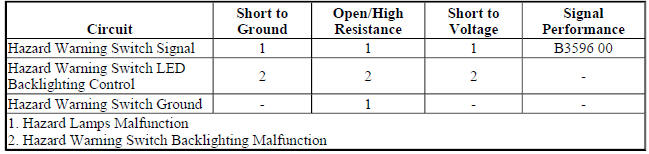
Circuit/System Description
The hazard flashers may be activated in any power mode. The hazard warning switch signal circuit is momentarily grounded when the hazard warning switch is pressed. The body control module (BCM) responds to the hazard warning switch signal input by supplying battery voltage to all four turn signal lamps in an ON and OFF duty cycle. When the hazard warning switch is activated, the BCM sends a serial data message to the instrument cluster requesting both turn signal indicators to be cycled ON and OFF.
The instrument panel dimmer switch controls are located on the headlamp switch assembly and are used to increase and decrease the brightness of the interior backlighting components. When the instrument panel dimmer switch is placed in a desired brightness position, the body control module (BCM) receives a signal from the instrument panel dimmer switch and responds by applying a pulse width modulated (PWM) voltage to the hazard switch LED backlighting control circuit illuminating the LED to the desired level of brightness.
Reference Information
Schematic Reference
Exterior Lights Schematics (Encore) , Exterior Lights Schematics (Encore)
Connector End View Reference
WIRING SYSTEMS AND POWER MANAGEMENT - COMPONENT CONNECTOR END VIEWS - INDEX - ENCORE WIRING SYSTEMS AND POWER MANAGEMENT - COMPONENT CONNECTOR END VIEWS - INDEX - Encore
Description and Operation
Exterior Lighting Systems Description and Operation
Electrical Information Reference
- Circuit Testing
- Connector Repairs
- Testing for Intermittent Conditions and Poor Connections
- Wiring Repairs
Scan Tool Reference
Control Module References for scan tool information
Circuit/System Verification
- Ignition ON.
- Verify the scan tool Hazard Lamps Switch parameter changes between Active and Inactive while commanding the hazard lamps ON and OFF with the hazard warning switch.
- If the parameter does not change
Refer to Hazard Warning Switch Malfunction
- If the parameter changes
- Verify all left and right turn signal lamps turn ON and OFF while commanding the hazard lamps ON and OFF with the hazard warning switch.
- If all turn signal lamps do not turn ON and OFF
Refer to Turn Signal Lamps and/or Indicators Malfunction
- If all turn signal lamps turn ON and OFF
- Verify the hazard warning switch backlighting turns ON and OFF while commanding the Hazard Lamps Switch Backlight ON and OFF with a scan tool.
- If the hazard warning switch backlighting does not turn ON and OFF
Refer to Hazard Warning Switch Backlighting Malfunction.
- If the hazard warning switch backlighting turns ON and OFF
- All OK.
Circuit/System Testing
Hazard Warning Switch Malfunction
- Ignition OFF, scan tool disconnected, all doors closed, all accessories OFF, disconnect the harness connector at the S26 Hazard Warning Switch. It may take up to 2 minutes for all vehicle systems to power down.
- Test for less than 5 ohms between the ground circuit terminal 7 and ground.
- If 5 ohms or greater
- Ignition OFF.
- Test for less than 2 ohms in the ground circuit end to end.
- If 2 ohms or greater, repair the open/high resistance in the circuit.
- If less than 2 ohms, repair the open/high resistance in the ground connection.
- If less than 5 ohms
- Ignition ON.
- Verify the scan tool Hazard Lamps Switch parameter is Inactive.
- If not Inactive
- Ignition OFF, disconnect the X2 harness connector at the K9 Body Control Module.
- Test for infinite resistance between the signal circuit terminal 10 and ground.
- If less than infinite resistance, repair the short to ground on the circuit.
- If infinite resistance, replace the K9 Body Control Module.
- If Inactive
- Install a 3 A fused jumper wire between the signal circuit terminal 10 and ground.
- Verify the scan tool Hazard Lamps Switch parameter is Active.
- If not Active
- Ignition OFF, disconnect the X2 harness connector at the K9 Body Control Module, ignition ON.
- Test for less than 1 V between the signal circuit terminal 10 and ground.
- If 1 V or greater, repair the short to voltage on the circuit.
- If less than 1 V
- Test for less than 2 ohms in the signal circuit end to end.
- If 2 ohms or greater, repair the open/high resistance in the circuit.
- If less than 2 ohms, replace the K9 Body Control Module.
- If Active
- Test or replace the S26 Hazard Warning Switch.
Hazard Warning Switch Backlighting Malfunction
- Ignition OFF, scan tool disconnected, all doors closed, all accessories OFF, disconnect the harness connector at the S26 Hazard Warning Switch. It may take up to 2 minutes for all vehicle systems to power down.
- Test for less than 5 ohms between the ground circuit terminal 7 and ground.
- If 5 ohms or greater
- Ignition OFF.
- Test for less than 2 ohms in the ground circuit end to end.
- If 2 ohms or greater, repair the open/high resistance in the circuit.
- If less than 2 ohms, repair the open/high resistance in the ground connection.
- If less than 5 ohms
- Connect a test lamp between the control circuit terminal 5 and ground, ignition ON.
- Verify the test lamp turns ON and OFF when commanding the Hazard Lamps Switch Backlight ON and OFF with a scan tool.
- If the test lamp is always OFF
- Ignition OFF, disconnect the X1 harness connector at the K9 Body Control Module.
- Test for infinite resistance between the control circuit and ground.
- If less than infinite resistance, repair the short to ground on the circuit.
- If infinite resistance
- Test for less than 2 ohms in the control circuit end to end.
- If 2 ohms or greater, repair the open/high resistance in the circuit.
- If less than 2 ohms, replace the K9 Body Control Module.
- If the test lamp is always ON
- Ignition OFF, disconnect the X1 harness connector at the K9 Body Control Module, ignition ON.
- Test for less than 1 V between the control circuit terminal and ground.
- If 1 V or greater, repair the short to voltage on the circuit.
- If less than 1 V, replace the K9 Body Control Module.
- If the test lamp turns ON and OFF
- Test or replace the S26 Hazard Warning Switch.
Repair Instructions
Perform the Diagnostic Repair Verification after completing the repair.
- Hazard Warning and Accessory Switch Replacement (Encore)
- Control Module References for BCM replacement, programming, and setup
Headlamps malfunction
Diagnostic Instructions
- Perform the Diagnostic System Check - Vehicle prior to using this diagnostic procedure.
- Review Strategy Based Diagnosis for an overview of the diagnostic approach.
- Diagnostic Procedure Instructions provides an overview of each diagnostic category.
Diagnostic Fault Information
.jpg)
Circuit/System Description
The body control module (BCM) monitors three signal circuits from the headlamp switch. When the headlamp switch is in the AUTO position, all three signal circuits are open. When placed in the AUTO position, the BCM monitors inputs from the ambient light sensor to determine if headlamps are required or if daytime running lamps will be activated based on outside lighting conditions. When the headlamp switch is placed in the OFF position, the headlamp switch headlamps OFF signal circuit is grounded, indicating to the BCM that the exterior lamps should be turned OFF. With the headlamp switch in the PARK position, the headlamp switch park lamps ON signal circuit is grounded, indicating that the park lamps have been requested. When the headlamp switch is placed in the HEADLAMP position, both the headlamp switch park lamps ON signal circuit and the headlamp switch headlamps ON signal circuit are grounded. The BCM responds to the inputs by illuminating the park lamps and headlamps. When the low beam headlamps are requested, the BCM applies B+ to both low beam headlamp control circuits illuminating the low beam headlamps.
The high beam and flash to pass functions are contained within the turn signal/multifunction switch. The BCM provides the turn signal/multifunction switch with two signal circuits, the high beam signal circuit and the flash to pass signal circuit. When the low beam headlamps are ON and the turn signal/multifunction switch is placed in the high beam position, ground is applied to the BCM through the high beam signal circuit. The BCM responds to the high beam request by applying ground to the high beam relay control circuit which energizes the high beam relay. With the high beam relay energized, the switch contacts close allowing battery voltage to flow through the high beam fuses to the high beam control circuits illuminating the high beam headlamps.
When the turn signal/multifunction switch is momentarily placed in the flash to pass position, ground is applied to the BCM through the flash to pass signal circuit. The BCM responds by applying ground to the high beam relay control circuit which energizes the high beam relay illuminating the high beams for a brief moment or until the flash to pass switch is released.
Reference Information
Schematic Reference
- Headlights/Daytime Running Lights (DRL) Schematics (Encore) , Headlights/Daytime Running Lights (DRL) Schematics (Encore)
- Body Control System Schematics (Encore) , Body Control System Schematics (Encore)
Connector End View Reference
WIRING SYSTEMS AND POWER MANAGEMENT - COMPONENT CONNECTOR END VIEWS - INDEX - ENCORE WIRING SYSTEMS AND POWER MANAGEMENT - COMPONENT CONNECTOR END VIEWS - INDEX - Encore
Description and Operation
Exterior Lighting Systems Description and Operation
Electrical Information Reference
- Circuit Testing
- Connector Repairs
- Testing for Intermittent Conditions and Poor Connections
- Wiring Repairs
Scan Tool Reference
Control Module References for scan tool information
Circuit/System Verification
- Ignition ON.
- Verify the scan tool Headlamps On Switch parameter changes between Active and Inactive while commanding the headlamp ON and OFF with the headlamp switch.
- If the parameter does not change
Refer to Headlamp Switch Malfunction
- If the parameter changes
- Verify the scan tool Automatic Headlamps Disable Switch parameter changes between Active and Inactive while commanding the automatic lamp control ON and OFF with the headlamp switch.
- If the parameter does not change
Refer to Headlamp Switch Malfunction.
- If the parameter changes
- Verify the scan tool Headlamps Flash Switch parameter changes between Active and Inactive while commanding the flash to pass ON and OFF with the turn signal/multifunction switch.
- If the parameter does not change
Refer to Turn Signal/Multifunction Switch Malfunction.
- If the parameter changes
- Verify the scan tool High Beam Select Switch parameter changes between Active and Inactive while commanding the high beams ON and OFF with the turn signal/multifunction switch.
- If the parameter does not change
Refer to Turn Signal/Multifunction Switch Malfunction.
- If the parameter changes
- Verify the left low beam/daytime running lamp turn ON and OFF when commanding the Left Low Beam/Daytime Running Lamp ON and OFF with a scan tool.
- If the left low beam/daytime running lamp does not turn ON and OFF
Refer to Headlamps Malfunction - Low Beam.
- If the left low beam/daytime running lamp turns ON and OFF
- Verify the right low beam/daytime running lamp turn ON and OFF when commanding the Right Low Beam/Daytime Running Lamp ON and OFF with a scan tool.
- If the right low beam/daytime running lamp does not turn ON and OFF
Refer to Headlamps Malfunction - Low Beam.
- If the right low beam/daytime running lamp turns ON and OFF
- Verify the high beams turn ON and OFF when commanding the High Beams ON and OFF with a scan tool.
- If the high beams do not turn ON and OFF
Refer to Headlamps Malfunction - High Beam.
- If the high beams turn ON and OFF
- Verify the high beam indicator on the instrument cluster turns ON and OFF while commanding the All Indicators Test ON and OFF with a scan tool.
- If the high beam indicator does not turn ON and OFF
Refer to High Beam Indicator Malfunction.
- If the high beam indicator turns ON and OFF
- All OK.
Circuit/System Testing
Headlamp Switch Malfunction
- Ignition OFF, scan tool disconnected, all doors closed, all accessories OFF, disconnect the harness connector at the S30 Headlamp Switch. It may take up to 2 minutes for all vehicle systems to power down.
- Test for less than 15 ohms between the ground circuit terminal 6 and ground.
- If 15 ohms or greater
- Ignition OFF.
- Test for less than 2 ohms in the ground circuit end to end.
- If 2 ohms or greater, repair the open/high resistance in the circuit.
- If less than 2 ohms, repair the open/high resistance in the ground connection.
- If less than 15 ohms
- Ignition ON.
- Verify the scan tool Automatic Headlamps Disable Switch parameter is Inactive.
- If not Inactive
- Ignition OFF, disconnect the X1 harness connector at the K9 Body Control Module.
- Test for infinite resistance between the signal circuit terminal 5 and ground.
- If less than infinite resistance, repair the short to ground on the circuit.
- If infinite resistance, replace the K9 Body Control Module.
- If Inactive
- Install a 3 A fused jumper wire between the signal circuit terminal 5 and the ground circuit terminal 6.
- Verify the scan tool Automatic Headlamps Disable Switch parameter is Active.
- If not Active
- Ignition OFF, disconnect the X1 harness connector at the K9 Body Control Module, ignition ON.
- Test for less than 1 V between the signal circuit terminal 5 and ground.
- If 1 V or greater, repair the short to voltage on the circuit.
- If less than 1 V
- Test for less than 2 ohms in the signal circuit end to end.
- If 2 ohms or greater, repair the open/high resistance in the circuit.
- If less than 2 ohms, replace the K9 Body Control Module.
- If Active
- Verify the scan tool Park Lamps Switch parameter is Inactive.
- If not Inactive
- Ignition OFF, disconnect the X1 harness connector at the K9 Body Control Module.
- Test for infinite resistance between the signal circuit terminal 3 and ground.
- If less than infinite resistance, repair the short to ground on the circuit.
- If infinite resistance, replace the K9 Body Control Module.
- If Inactive
- Install a 3 A fused jumper wire between the signal circuit terminal 3 and the ground circuit terminal 6.
- Verify the scan tool Park Lamps Switch parameter is Active.
- If not Active
- Ignition OFF, disconnect the X1 harness connector at the K9 Body Control Module, ignition ON.
- Test for less than 1 V between the signal circuit terminal 3 and ground.
- If 1 V or greater, repair the short to voltage on the circuit.
- If less than 1 V
- Test for less than 2 ohms in the signal circuit end to end.
- If 2 ohms or greater, repair the open/high resistance in the circuit.
- If less than 2 ohms, replace the K9 Body Control Module.
- If Active
- Verify the scan tool Headlamps On Switch parameter is Inactive.
- If not Inactive
- Ignition OFF, disconnect the X1 harness connector at the K9 Body Control Module.
- Test for infinite resistance between the signal circuit terminal 4 and ground.
- If less than infinite resistance, repair the short to ground on the circuit.
- If infinite resistance, replace the K9 Body Control Module.
- If Inactive
- Install a 3 A fused jumper wire between the signal circuit terminal 4 and the ground circuit terminal 6.
- Verify the scan tool Headlamps On Switch parameter is Active.
- If not Active
- Ignition OFF, disconnect the X1 harness connector at the K9 Body Control Module, ignition ON.
- Test for less than 1 V between the signal circuit terminal 4 and ground.
- If 1 V or greater, repair the short to voltage on the circuit.
- If less than 1 V
- Test for less than 2 ohms in the signal circuit end to end.
- If 2 ohms or greater, repair the open/high resistance in the circuit.
- If less than 2 ohms, replace the K9 Body Control Module.
- If Active
- Test or replace the S30 Headlamp Switch.
Turn Signal/Multifunction Switch Malfunction
- Ignition OFF, scan tool disconnected, all doors closed, all accessories OFF, disconnect the harness connector at the S78 Turn Signal/Multifunction Switch. It may take up to 2 minutes for all vehicle systems to power down.
- Test for less than 15 ohms between the ground circuit terminal 3 and ground.
- If 15 ohms or greater
- Ignition OFF.
- Test for less than 2 ohms in the ground circuit end to end.
- If 2 ohms or greater, repair the open/high resistance in the circuit.
- If less than 2 ohms, repair the open/high resistance in the ground connection.
- If less than 15 ohms
- Ignition ON.
- Verify the scan tool High Beam Select Switch parameter is Inactive.
- If not Inactive
- Ignition OFF, disconnect the X3 harness connector at the K9 Body Control Module.
- Test for infinite resistance between the signal circuit terminal 2 and ground.
- If less than infinite resistance, repair the short to ground on the circuit.
- If infinite resistance, replace the K9 Body Control Module.
- If Inactive
- Install a 3 A fused jumper wire between the signal circuit terminal 2 and the ground circuit terminal 3.
- Verify the scan tool High Beam Select Switch parameter is Active.
- If not Active
- Ignition OFF, disconnect the X3 harness connector at the K9 Body Control Module, ignition ON.
- Test for less than 1 V between the signal circuit terminal 2 and ground.
- If 1 V or greater, repair the short to voltage on the circuit.
- If less than 1 V
- Test for less than 2 ohms in the signal circuit end to end.
- If 2 ohms or greater, repair the open/high resistance in the circuit.
- If less than 2 ohms, replace the K9 Body Control Module.
- If Active
- Verify the scan tool Headlamps Flash Switch parameter is Inactive.
- If not Inactive
- Ignition OFF, disconnect the X3 harness connector at the K9 Body Control Module.
- Test for infinite resistance between the signal circuit terminal 4 and ground.
- If less than infinite resistance, repair the short to ground on the circuit.
- If infinite resistance, replace the K9 Body Control Module.
- If Inactive
- Install a 3 A fused jumper wire between the signal circuit terminal 4 and the ground circuit terminal 3.
- Verify the scan tool Headlamps Flash Switch parameter is Active.
- If not Active
- Ignition OFF, disconnect the X3 harness connector at the K9 Body Control Module, ignition ON.
- Test for less than 1 V between the signal circuit terminal 4 and ground.
- If 1 V or greater, repair the short to voltage on the circuit.
- If less than 1 V
- Test for less than 2 ohms in the signal circuit end to end.
- If 2 ohms or greater, repair the open/high resistance in the circuit.
- If less than 2 ohms, replace the K9 Body Control Module.
- If Active
- Test or replace the S78 Turn Signal/Multifunction Switch.
Headlamps Malfunction - Low Beam
- Ignition OFF, exterior lamps OFF, remove the appropriate E4 Headlamp - Low Beam bulb.
- Test for less than 10 ohms between the ground circuit at the socket terminal and ground.
- If 10 ohms or greater
- Ignition OFF.
- Test for less than 2 ohms in the ground circuit end to end.
- If 2 ohms or greater, repair the open/high resistance in the circuit.
- If less than 2 ohms, repair the open/high resistance in the ground connection.
- If less than 10 ohms
- Connect a test lamp between the control circuit at the socket terminal and ground, ignition ON.
- Verify the test lamp turns ON and OFF when commanding the appropriate Low Beam/Daytime Running Lamp ON and OFF with a scan tool.
- If the test lamp is always OFF
- Ignition OFF, disconnect the X4 harness connector at the K9 Body Control Module.
- Test for infinite resistance between the control circuit and ground.
- If less than infinite resistance, repair the short to ground on the circuit.
- If infinite resistance
- Test for less than 2 ohms in the control circuit end to end.
- If 2 ohms or greater, repair the open/high resistance in the circuit.
- If less than 2 ohms, replace the K9 Body Control Module.
- If the test lamp is always ON
- Ignition OFF, disconnect the X4 harness connector at the K9 Body Control Module, ignition ON.
- Test for less than 1 V between the control circuit terminal and ground.
- If 1 V or greater, repair the short to voltage on the circuit.
- If less than 1 V, replace the K9 Body Control Module.
- If the test lamp turns ON and OFF
- Test or replace the appropriate E4 Headlamp - Low Beam.
Headlamps Malfunction - High Beam
- Ignition OFF, disconnect the X5 harness connector at the K9 Body Control Module, ignition ON.
- Verify a test lamp illuminates between the control circuit terminal 18 and ground.
- If the test lamp does not illuminate
- Ignition OFF, disconnect the X2 harness connector at the X50A Fuse Block - Underhood.
- Test for infinite resistance between the control circuit terminal and ground.
- If less than infinite resistance, repair the short to ground on the circuit.
- If infinite resistance
- Test for less than 2 ohms in the control circuit end to end.
- If 2 ohms or greater, repair the open/high resistance in the circuit.
- If less than 2 ohms, replace the X50A Fuse Block - Underhood.
- If the test lamp illuminates
- Ignition OFF, connect a 3 A fused jumper between the control circuit terminal 18 and ground.
- Remove the F31UA fuse at the X50A Fuse Block - Underhood.
- Verify a test lamp illuminates between the F31UA fuse B+ switch control terminal and ground.
- If the test lamp does not illuminate
- Ignition OFF, disconnect the X2 harness connector at the X50A Fuse Block - Underhood, ignition ON.
- Test for less than 1 V between the control circuit terminal 18 and ground.
- If 1 V or greater, repair the short to voltage on the circuit.
- If less than 1 V, replace the X50A Fuse Block - Underhood.
- If the test lamp illuminates
- Ignition OFF, connect the X5 harness connector at the K9 Body Control Module.
- Install the F31UA fuse at the X50A Fuse Block - Underhood.
- Remove the appropriate E4 Headlamp - High Beam bulb.
- Test for less than 10 ohms between the ground circuit at the socket terminal and ground.
- If 10 ohms or greater
- Ignition OFF.
- Test for less than 2 ohms in the ground circuit end to end.
- If 2 ohms or greater, repair the open/high resistance in the circuit.
- If less than 2 ohms, repair the open/high resistance in the ground connection.
- If less than 10 ohms
- Connect a test lamp between the control circuit at the socket terminal and ground, ignition ON.
- Verify the test lamp turns ON and OFF when commanding the High Beams ON and OFF with a scan tool.
- If the test lamp is always OFF
- Ignition OFF, disconnect the X1 harness connector at the X50A Fuse Block - Underhood.
- Test for infinite resistance between the control circuit and ground.
- If less than infinite resistance, repair the short to ground on the circuit.
- If infinite resistance
- Test for less than 2 ohms in the control circuit end to end.
- If 2 ohms or greater, repair the open/high resistance in the circuit.
- If less than 2 ohms, replace the K9 Body Control Module.
- If the test lamp is always ON
- Ignition OFF, disconnect the X1 harness connector at the X50A Fuse Block - Underhood, ignition ON.
- Test for less than 1 V between the control circuit terminal and ground.
- If 1 V or greater, repair the short to voltage on the circuit.
- If less than 1 V, replace the K9 Body Control Module.
- If the test lamp turns ON and OFF
- Test or replace the appropriate E4 Headlamp - High Beam.
High Beam Indicator Malfunction
- Ignition ON.
- Verify the high beam indicator turns ON and OFF when commanding the Instrument Cluster All Indicators Test ON and OFF with a scan tool.
- If the high beam indicator is always OFF or remains ON
Replace the P16 Instrument Cluster.
- If the high beam indicator turns ON and OFF
- Replace the K9 Body Control Module.
Repair Instructions
Perform the Diagnostic Repair Verification after completing the repair
- Headlamp Switch Replacement (Encore) , Headlamp Switch Replacement (Encore)
- Relay Replacement (Within an Electrical Center) , Relay Replacement (Attached to Wire Harness)
- Turn Signal Switch Replacement (Encore) , Turn Signal Switch Replacement (Encore)
- Headlamp Bulb Replacement - Left Side (Encore High Beam) , Headlamp Bulb Replacement - Left Side (Encore Low Beam)
- Headlamp Bulb Replacement - Right Side (High Beam) , Headlamp Bulb Replacement - Right Side (Low Beam)
- Front Compartment Fuse Block Replacement
- Control Module References for BCM or Instrument Cluster replacement, programming, and setup
Interior accent lighting malfunction
Diagnostic Instructions
- Perform the Diagnostic System Check - Vehicle prior to using this diagnostic procedure.
- Review Strategy Based Diagnosis for an overview of the diagnostic approach.
- Diagnostic Procedure Instructions provides an overview of each diagnostic category.
Diagnostic Fault Information
.jpg)
Circuit/System Description
The instrument panel dimmer switch is used to increase and decrease the brightness of the interior backlighting components. The instrument panel dimmer switch provides a voltage signal to the body control module (BCM) that will increase as the brightness of the lights are increased and decrease as the brightness of the lights are decreased. The BCM provides a low reference signal and B+ to the instrument panel dimmer switch. When the instrument panel dimmer switch is placed in the desired position, the dimmed voltage setting is applied from the instrument panel dimmer switch through the instrument panel dimmer switch signal circuit to the BCM. The BCM interprets the signal and applies a pulse width modulated (PWM) voltage through the LED dimming control circuits illuminating the interior backlighting to the requested level of brightness.
Reference Information
Schematic Reference
Interior Lights Schematics (Encore) , Interior Lights Schematics (Encore)
Connector End View Reference
WIRING SYSTEMS AND POWER MANAGEMENT - COMPONENT CONNECTOR END VIEWS - INDEX - ENCORE WIRING SYSTEMS AND POWER MANAGEMENT - COMPONENT CONNECTOR END VIEWS - INDEX - Encore
Description and Operation
Interior Lighting Systems Description and Operation
Electrical Information Reference
- Circuit Testing
- Connector Repairs
- Testing for Intermittent Conditions and Poor Connections
- Wiring Repairs
Scan Tool Reference
Control Module References
Circuit/System Testing
NOTE: Each accent lamp may need to be disconnected to isolate the short to ground. Use the schematic to identify the following:
- All accent lamps equipped with the vehicle
- Component locations on the accent light control circuit
- Each component's control circuit terminals
- Ignition OFF, scan tool disconnected, all doors closed, all accessories OFF, disconnect the X1 harness connector at the appropriate E1 Accent Lamp. It may take up to 2 minutes for all vehicle systems to power down.
- Test for less than 15 ohms between the ground circuit terminal 1 and ground.
- If 15 ohms or greater
- Ignition OFF.
- Test for less than 2 ohms in the ground circuit end to end.
- If 2 ohms or greater, repair the open/high resistance in the circuit.
- If less than 2 ohms, repair the open/high resistance in the ground connection.
- If less than 15 ohms
- Connect a test lamp between the control circuit terminal 2 and ground, ignition ON.
- Verify the test lamp turns ON and OFF when commanding the Accent Lighting 1 ON and OFF with a scan tool.
- If the test lamp is always OFF
- Ignition OFF, disconnect the X6 harness connector at the K9 Body Control Module.
- Test for infinite resistance between the control circuit and ground.
- If less than infinite resistance, repair the short to ground on the circuit.
- If infinite resistance
- Test for less than 2 ohms in the control circuit end to end.
- If 2 ohms or greater, repair the open/high resistance in the circuit.
- If less than 2 ohms, replace the K9 Body Control Module.
- If the test lamp is always ON
- Ignition OFF, disconnect the X6 harness connector at the K9 Body Control Module, ignition ON.
- Test for less than 1 V between the control circuit terminal and ground.
- If 1 V or greater, repair the short to voltage on the circuit.
- If less than 1 V, replace the K9 Body Control Module.
- If the test lamp turns ON and OFF
- Test or replace the appropriate E1 Accent Lamp
Repair Instructions
Perform the Diagnostic Repair Verification after completing the repair.
Control Module References for BCM replacement, programming, and setup
Interior backlighting malfunction
Diagnostic Instructions
- Perform the Diagnostic System Check - Vehicle prior to using this diagnostic procedure.
- Review Strategy Based Diagnosis for an overview of the diagnostic approach.
- Diagnostic Procedure Instructions provides an overview of each diagnostic category
Diagnostic Fault Information

Circuit/System Description
The instrument panel dimmer switch is used to increase and decrease the brightness of the interior backlighting components. The instrument panel dimmer switch provides a voltage signal to the body control module (BCM) that will increase as the brightness of the lights are increased and decrease as the brightness of the lights are decreased. The BCM provides a low reference signal and a B+ voltage reference to the instrument panel dimmer switch. When the instrument panel dimmer switch is placed in the desired position, the dimmed voltage setting is applied from the instrument panel dimmer switch through the instrument panel dimmer switch signal circuit to the BCM. The BCM interprets the signal and applies a pulse width modulated (PWM) voltage through the LED dimming control circuits illuminating the interior backlighting to the requested level of brightness.
Reference Information
Schematic Reference
Interior Lights Dimming Schematics (Encore) , Interior Lights Dimming Schematics (Encore)
Connector End View Reference
WIRING SYSTEMS AND POWER MANAGEMENT - COMPONENT CONNECTOR END VIEWS - INDEX - ENCORE WIRING SYSTEMS AND POWER MANAGEMENT - COMPONENT CONNECTOR END VIEWS - INDEX - Encore
Description and Operation
Interior Lighting Systems Description and Operation
Electrical Information Reference
- Circuit Testing
- Connector Repairs
- Testing for Intermittent Conditions and Poor Connections Wiring Repairs
Scan Tool Reference
Control Module References for scan tool information
Circuit/System Verification
- Ignition ON.
- Verify the scan tool LED Backlight Dimming Command parameter changes between a high percentage to a low percentage while operating the dimmer switch from high to low.
- If the parameter does not change
Refer to Dimmer Switch Malfunction.
- If the parameter changes
- Verify the child safety lock switch amber LED indicator turns ON and OFF while commanding the Child Safety Lock Indicator ON and OFF with a scan tool.
- If the child safety lock switch amber indicator does turn ON and OFF
Refer to Multifunction Switch Amber Indicator Malfunction.
- If the child safety lock switch amber indicator turns ON and OFF
- Verify all backlighting components turn ON and OFF while commanding the LED Backlight Dimming ON and OFF with a scan tool.
- If all backlighting components do not turn ON and OFF
Refer to Interior Backlighting Malfunction.
- If all backlighting components turn ON and OFF
- All OK.
Circuit/System Testing
Dimmer Switch Malfunction
- Ignition OFF and all vehicle systems OFF, disconnect the harness connector at the S30 Headlamp Switch, ignition ON.
- Test for B+ between the B+ circuit terminal 1 and ground.
- If less than B+
- Ignition OFF, disconnect the X3 harness connector at the K9 Body Control Module.
- Test for infinite resistance between the B+ circuit and ground.
- If less than infinite resistance, repair the short to ground on the circuit.
- If infinite resistance
- Test for less than 2 ohms in the B+ circuit end to end.
- If 2 ohms or greater, repair the open/high resistance in the circuit.
- If less than 2 ohms, replace the K9 Body Control Module.
- If B+
- Verify a test lamp does not illuminate between the B+ circuit terminal 1 and the signal circuit terminal 12.
- If the test lamp illuminates
- Ignition OFF, disconnect the X1 harness connector at the K9 Body Control Module.
- Test for infinite resistance between the signal circuit and ground.
- If less than infinite resistance, repair the short to ground on the circuit.
- If infinite resistance, replace the K9 Body Control Module.
- If the test lamp does not illuminate
- Test for B+ between the B+ circuit terminal 1 and the signal circuit terminal 12.
- If less than B+
- Ignition OFF, disconnect the X1 harness connector at the K9 Body Control Module, ignition ON.
- Test for less than 1 V between the signal circuit terminal 12 and ground.
- If 1 V or greater, repair the short to voltage on the circuit.
- If less than 1 V
- Test for less than 2 ohms in the signal circuit end to end.
- If 2 ohms or greater, repair the open/high resistance in the circuit.
- If less than 2 ohms, replace the K9 Body Control Module.
- If B+
- Test or replace the S30 Headlamp Switch.
Multifunction Switch Amber Indicator Malfunction
- Ignition OFF, disconnect the appropriate harness connector listed below at the S48E Multifunction Switch - Center Console.
- X1
- X2
- Connect a test lamp between the control circuit terminal 8 and ground, ignition ON.
- Verify the test lamp turns ON and OFF when commanding the Child Safety Lock Indicator ON and OFF with a scan tool.
- If the test lamp is always OFF
- Ignition OFF, disconnect the X1 harness connector at the K9 Body Control Module.
- Test for infinite resistance between the control circuit and ground.
- If less than infinite resistance, repair the short to ground on the circuit.
- If infinite resistance
- Test for less than 2 ohms in the control circuit end to end.
- If 2 ohms or greater, repair the open/high resistance in the circuit.
- If less than 2 ohms, replace the K9 Body Control Module.
- If the test lamp is always ON
- Ignition OFF, disconnect the X1 harness connector at the K9 Body Control Module, ignition ON.
- Test for less than 1 V between the control circuit terminal and ground.
- If 1 V or greater, repair the short to voltage on the circuit.
- If less than 1 V, replace the K9 Body Control Module.
- If the test lamp turns ON and OFF
- Test or replace the appropriate switch at the S48E Multifunction Switch - Center Console.
Interior Backlighting Malfunction
NOTE: Each component with backlighting may need to be disconnected to isolate a short to voltage or short to ground. Use the schematics to identify the following:
- Backlighting components the vehicle is equipped with
- Each component's control and ground circuit terminals
- Component locations on the backlighting control circuit
- Ignition OFF, disconnect the X1 harness connector at the K9 Body Control Module, ignition ON.
- Verify a test lamp illuminates between the B+ circuit terminal 4 and ground.
- If the test lamp does not illuminate and the circuit fuse is good
- Ignition OFF.
- Test for less than 2 ohms in the B+ circuit end to end.
- If 2 ohms or greater, repair the open/high resistance in the circuit.
- If less than 2 ohms, verify the fuse is not open and there is voltage at the fuse.
- If the test lamp does not illuminate and the circuit fuse is open
- Ignition OFF.
- Test for infinite resistance between the B+ circuit and ground.
- If less than infinite resistance, repair the short to ground on the circuit.
- If infinite resistance, replace the K9 Body Control Module.
- If the test lamp illuminates
- Ignition OFF, connect the X1 harness connector at the K9 Body Control Module.
- Ignition OFF, all doors closed, all accessories OFF, disconnect the harness connector at the component with inoperative backlighting. It may take up to 2 minutes for all vehicle systems to power down.
- Test for less than 15 ohms between the appropriate ground circuit terminal and ground.
- If 15 ohms or greater
- Ignition OFF.
- Test for less than 2 ohms in the ground circuit end to end.
- If 2 ohms or greater, repair the open/high resistance in the circuit.
- If less than 2 ohms, repair the open/high resistance in the ground connection.
- If less than 15 ohms
- Connect a test lamp between the appropriate control circuit terminal and ground.
- Verify the test lamp turns ON and OFF when commanding the LED Backlight Dimming ON and OFF with a scan tool.
- If the test lamp is always OFF
- Ignition OFF, disconnect the appropriate harness connector at the K9 Body Control Module.
- Test for infinite resistance between the control circuit and ground.
- If less than infinite resistance, repair the short to ground on the circuit.
- If infinite resistance
- Test for less than 2 ohms in the control circuit end to end.
- If 2 ohms or greater, repair the open/high resistance in the circuit.
- If less than 2 ohms, replace the K9 Body Control Module.
- If the test lamp is always ON
- Ignition OFF, disconnect the appropriate harness connector at the K9 Body Control Module, ignition ON.
- Test for less than 1 V between the control circuit terminal and ground.
- If 1 V or greater, repair the short to voltage on the circuit.
- If less than 1 V, replace the K9 Body Control Module.
- If the test lamp turns ON and OFF
- Test or replace the component with inoperative backlighting.
Hazard Warning Switch Backlighting Malfunction
- Ignition OFF, scan tool disconnected, all doors closed, all accessories OFF, disconnect the harness connector at the S26 Hazard Warning Switch. It may take up to 2 minutes for all vehicle systems to power down.
- Test for less than 5 ohms between the ground circuit terminal 7 and ground.
- If 5 ohms or greater
- Ignition OFF.
- Test for less than 2 ohms in the ground circuit end to end.
- If 2 ohms or greater, repair the open/high resistance in the circuit.
- If less than 2 ohms, repair the open/high resistance in the ground connection.
- If less than 5 ohms
- Connect a test lamp between the control circuit terminal 5 and ground, ignition ON.
- Verify the test lamp turns ON and OFF when commanding the Hazard Lamps Switch Backlight ON and OFF with a scan tool.
- If the test lamp is always OFF
- Ignition OFF, disconnect the X1 harness connector at the K9 Body Control Module.
- Test for infinite resistance between the control circuit and ground.
- If less than infinite resistance, repair the short to ground on the circuit.
- If infinite resistance
- Test for less than 2 ohms in the control circuit end to end.
- If 2 ohms or greater, repair the open/high resistance in the circuit.
- If less than 2 ohms, replace the K9 Body Control Module.
- If the test lamp is always ON
- Ignition OFF, disconnect the X1 harness connector at the K9 Body Control Module, ignition ON.
- Test for less than 1 V between the control circuit terminal and ground.
- If 1 V or greater, repair the short to voltage on the circuit.
- If less than 1 V, replace the K9 Body Control Module.
- If the test lamp turns ON and OFF
- Test or replace the S26 Hazard Warning Switch.
Repair Instructions
Perform the Diagnostic Repair Verification after completing the repair.
- Rear Side Door Window Switch Replacement
- Instrument Panel Multifunction Switch Replacement (Encore)
- Hazard Warning and Accessory Switch Replacement (Encore)
- Headlamp Switch Replacement (Encore) , Headlamp Switch Replacement (Encore)
- Door Lock Switch Replacement - Driver Side (Encore) , Door Lock Switch Replacement - Driver Side (Encore)
- Door Lock Switch Replacement - Passenger Front (Encore) , Door Lock Switch Replacement - Passenger Front (Encore)
- Transmission Control Replacement
- Outside Rearview Mirror Remote Control Switch Replacement (Encore) , Outside Rearview Mirror Remote Control Switch Replacement (Encore)
- Radio and Telephone Control Switch Replacement
- Control Module References for BCM replacement, programming, and setup
Park, license, and/or tail lamps malfunction
Diagnostic Instructions
- Perform the Diagnostic System Check - Vehicle prior to using this diagnostic procedure.
- Review Strategy Based Diagnosis for an overview of the diagnostic approach.
- Diagnostic Procedure Instructions provides an overview of each diagnostic category.
Diagnostic Fault Information
.jpg)

Circuit/System Description
When the headlamp switch is placed in the HEAD or PARK position, ground is applied to the park lamp switch ON signal circuit to the body control module (BCM). The BCM responds by applying voltage to the park lamps, tail lamps, and license lamps control circuits illuminating the park, tail, and license lamps.
Diagnostic Aids
When testing at the park lamp bulb socket, make sure all measurements and test lamp connections are in the correct terminal location and do not come in contact with each other during testing.
Reference Information
Schematic Reference
Exterior Lights Schematics (Encore) , Exterior Lights Schematics (Encore)
Connector End View Reference
WIRING SYSTEMS AND POWER MANAGEMENT - COMPONENT CONNECTOR END VIEWS - INDEX - ENCORE WIRING SYSTEMS AND POWER MANAGEMENT - COMPONENT CONNECTOR END VIEWS - INDEX - Encore
Description and Operation
Exterior Lighting Systems Description and Operation
Electrical Information Reference
- Circuit Testing
- Connector Repairs
- Testing for Intermittent Conditions and Poor Connections
- Wiring Repairs
Scan Tool Reference
Control Module References for scan tool information
Circuit/System Verification
- Ignition ON.
- Verify the scan tool Park Lamp Switch parameter changes between Active and Inactive while commanding the park lamps ON and OFF with the headlamp switch.
- If the parameter does not change
Refer to Park Lamp Switch Malfunction.
- If the parameter changes
- Verify the left park lamps turn ON and OFF when commanding the Left Park Lamps ON and OFF with a scan tool.
- If the left park lamps do not turn ON and OFF
Refer to Park Lamps Malfunction.
- If the left park lamps turn ON and OFF
- Verify the right park lamps turn ON and OFF when commanding the Right Park Lamps ON and OFF with a scan tool.
- If the right park lamps do not turn ON and OFF
Refer to Park Lamps Malfunction.
- If the right park lamps turn ON and OFF
- Verify the license plate lamps turn ON and OFF when commanding the License Plate Lamps ON and OFF with a scan tool.
- If the license plate lamps do not turn ON and OFF
Refer to License Plate Lamps Malfunction
- If the license plate lamps turn ON and OFF
- All OK.
Circuit/System Testing
Park Lamp Switch Malfunction
- Ignition OFF, all doors closed, all accessories OFF, disconnect the harness connector at the S30 Headlamp Switch. It may take up to 2 minutes for all vehicle systems to power down.
- Test for less than 15 ohms between the ground circuit terminal 6 and ground.
If 15 ohms or greater
- Ignition OFF.
- Test for less than 2 ohms in the ground circuit end to end.
- If 2 ohms or greater, repair the open/high resistance in the circuit.
- If less than 2 ohms, repair the open/high resistance in the ground connection.
- If less than 15 ohms
- Ignition ON.
- Verify the scan tool Park Lamps Switch parameter is Inactive.
- If not Inactive
- Ignition OFF, disconnect the X1 harness connector at the K9 Body Control Module.
- Test for infinite resistance between the signal circuit terminal 3 and ground.
- If less than infinite resistance, repair the short to ground on the circuit.
- If infinite resistance, replace the K9 Body Control Module.
- If Inactive
- Install a 3 A fused jumper wire between the signal circuit terminal 3 and the ground circuit terminal 6.
- Verify the scan tool Park Lamps Switch parameter is Active.
- If not Active
- Ignition OFF, disconnect the X1 harness connector at the K9 Body Control Module, ignition ON.
- Test for less than 1 V between the signal circuit terminal 3 and ground.
- If 1 V or greater, repair the short to voltage on the circuit.
- If less than 1 V
- Test for less than 2 ohms in the signal circuit end to end.
- If 2 ohms or greater, repair the open/high resistance in the circuit.
- If less than 2 ohms, replace the K9 Body Control Module.
- If Active
- Test or replace the S30 Headlamp Switch.
Park Lamps Malfunction
- Ignition OFF, exterior lamps OFF, rear hatch latch latched, disconnect the harness connector at the appropriate park lamp.
- Test for less than 10 ohms between the appropriate ground circuit terminal listed below and ground.
- E4J Park Lamp - Left Front socket terminal
- E4K Park Lamp - Right Front socket terminal
- E2LR Side Marker Lamp - Left Rear socket terminal
- E2RR Side Marker Lamp - Right Rear socket terminal
- If 10 ohms or greater
- Ignition OFF.
- Test for less than 2 ohms in the ground circuit end to end.
- If 2 ohms or greater, repair the open/high resistance in the circuit.
- If less than 2 ohms, repair the open/high resistance in the ground connection.
- If less than 10 ohms
- Connect a test lamp between the appropriate control circuit terminal listed below and ground, ignition ON.
- E4J Park Lamp - Left Front socket terminal
- E4K Park Lamp - Right Front socket terminal
- E2LR Side Marker Lamp - Left Rear socket terminal
- E2RR Side Marker Lamp - Right Rear socket terminal
- Verify the test lamp turns ON and OFF when commanding the appropriate Park Lamps ON and OFF with a scan tool.
- If the test lamp is always OFF
- Ignition OFF, disconnect the appropriate harness connector listed below at the K9 Body Control Module.
- X4
- X5
- Test for infinite resistance between the control circuit and ground.
- If less than infinite resistance, repair the short to ground on the circuit.
- If infinite resistance
- Test for less than 2 ohms in the control circuit end to end.
- If 2 ohms or greater, repair the open/high resistance in the circuit.
- If less than 2 ohms, replace the K9 Body Control Module.
- If the test lamp is always ON
- Ignition OFF, disconnect the appropriate harness connector listed below at the K9 Body Control Module, ignition ON.
- X4
- X5
- Test for less than 1 V between the control circuit terminal and ground.
- If 1 V or greater, repair the short to voltage on the circuit.
- If less than 1 V, replace the K9 Body Control Module.
- If the test lamp turns ON and OFF
- Test or replace the appropriate park lamp.
License Plate Lamps Malfunction
- Ignition OFF, exterior lamps OFF, rear hatch latch latched, remove both E7 License Plate Lamp bulbs.
- Test for less than 5 ohms between each ground circuit terminal 2 and ground.
- If 5 ohms or greater
- Ignition OFF.
- Test for less than 2 ohms in the ground circuit end to end.
- If 2 ohms or greater, repair the open/high resistance in the circuit.
- If less than 2 ohms, repair the open/high resistance in the ground connection.
- If less than 5 ohms
- Connect a test lamp between the E7L License Plate Lamp - Left control circuit terminal 1 and ground, ignition ON.
- Verify the test lamp turns ON and OFF when commanding the License Plate Lamps ON and OFF with a scan tool.
- If the test lamp is always OFF
- Ignition OFF, disconnect the X4 harness connector at the K9 Body Control Module.
- Test for infinite resistance between the control circuit and ground.
- If less than infinite resistance, repair the short to ground on the circuit.
- If infinite resistance
- Test for less than 2 ohms in the control circuit end to end.
- If 2 ohms or greater, repair the open/high resistance in the circuit.
- If less than 2 ohms, replace the K9 Body Control Module.
- If the test lamp is always ON
- Ignition OFF, disconnect the X4 harness connector at the K9 Body Control Module, ignition ON.
- Test for less than 1 V between the control circuit terminal and ground.
- If 1 V or greater, repair the short to voltage on the circuit.
- If less than 1 V, replace the K9 Body Control Module.
- If the test lamp turns ON and OFF
- Connect a test lamp between the E7R License Plate Lamp - Right control circuit terminal 1 and ground, ignition ON.
- Verify the test lamp turns ON and OFF when commanding the License Plate Lamps ON and OFF with a scan tool.
- If the test lamp is always OFF
- Ignition OFF, disconnect the X4 harness connector at the K9 Body Control Module.
- Test for infinite resistance between the control circuit and ground.
- If less than infinite resistance, repair the short to ground on the circuit.
- If infinite resistance
- Test for less than 2 ohms in the control circuit end to end.
- If 2 ohms or greater, repair the open/high resistance in the circuit.
- If less than 2 ohms, replace the K9 Body Control Module.
- If the test lamp turns ON and OFF
- Test or replace the appropriate E7 License Plate Lamp bulb.
Repair Instructions
Perform the Diagnostic Repair Verification after completing the repair.
- Headlamp Switch Replacement (Encore) , Headlamp Switch Replacement (Encore)
- Tail Lamp Replacement (Encore) , Tail Lamp Replacement (Encore)
- Parking and Turn Signal Lamp Bulb Replacement (Left Hand) , Parking and Turn Signal Lamp Bulb Replacement (Right Hand)
- Rear License Plate Lamp Bulb Replacement
- Control Module References for BCM replacement, programming, and setup
Rear compartment lamp malfunction
Diagnostic Instructions
- Perform the Diagnostic System Check - Vehicle prior to using this diagnostic procedure.
- Review Strategy Based Diagnosis for an overview of the diagnostic approach.
- Diagnostic Procedure Instructions provides an overview of each diagnostic category
Diagnostic Fault Information
.jpg)
Circuit/System Description
The body control module (BCM) applies battery voltage to the rear compartment courtesy lamp through the rear compartment lamp control circuit. When the BCM receives a rear compartment lid open input from the rear compartment lid latch, the BCM applies battery voltage to the rear compartment lamp control circuit illuminating the rear compartment courtesy lamp. In the event that the rear compartment lamp were to remain illuminated for more than 10 minutes with the ignition switch in the OFF position and no doors opened, the BCM will deactivate the rear compartment lamp control circuit to prevent total battery discharge.
Reference Information
Schematic Reference
Interior Lights Schematics (Encore) , Interior Lights Schematics (Encore)
Connector End View Reference
WIRING SYSTEMS AND POWER MANAGEMENT - COMPONENT CONNECTOR END VIEWS - INDEX - ENCORE WIRING SYSTEMS AND POWER MANAGEMENT - COMPONENT CONNECTOR END VIEWS - INDEX - Encore
Description and Operation
Interior Lighting Systems Description and Operation
Electrical Information Reference
- Circuit Testing
- Connector Repairs
- Testing for Intermittent Conditions and Poor Connections
- Wiring Repairs
Scan Tool Reference
Control Module References for scan tool information
Circuit/System Testing
- Ignition OFF, exterior lamps OFF, rear hatch latch latched, disconnect the harness connector at the E8S Rear Compartment Courtesy Lamp.
- Test for less than 5 ohms between the ground circuit terminal 2 and ground.
- If 5 ohms or greater
- Ignition OFF.
- Test for less than 2 ohms in the ground circuit end to end.
- If 2 ohms or greater, repair the open/high resistance in the circuit.
- If less than 2 ohms, repair the open/high resistance in the ground connection.
- If less than 5 ohms
- Connect a test lamp between the control circuit terminal 1 and ground, ignition ON.
- Verify the test lamp turns ON and OFF when commanding the Cargo Lamp ON and OFF with a scan tool.
- If the test lamp is always OFF
- Ignition OFF, disconnect the X7 harness connector at the K9 Body Control Module.
- Test for infinite resistance between the control circuit and ground.
- If less than infinite resistance, repair the short to ground on the circuit.
- If infinite resistance
- Test for less than 2 ohms in the control circuit end to end.
- If 2 ohms or greater, repair the open/high resistance in the circuit.
- If less than 2 ohms, replace the K9 Body Control Module.
- If the test lamp is always ON
- Ignition OFF, disconnect the X7 harness connector at the K9 Body Control Module, ignition ON.
- Test for less than 1 V between the control circuit terminal and ground.
- If 1 V or greater, repair the short to voltage on the circuit.
- If less than 1 V, replace the K9 Body Control Module.
If the test lamp turns ON and OFF
- Test or replace the E8S Rear Compartment Courtesy Lamp
Repair Instructions
Perform the Diagnostic Repair Verification after completing the repair.
- Cargo Lamp Replacement
- Cargo Center Courtesy Lamp Bulb Replacement
- Control Module References for BCM replacement, programming, and setup
Stop lamps malfunction
Diagnostic Instructions
- Perform the Diagnostic System Check - Vehicle prior to using this diagnostic procedure.
- Review Strategy Based Diagnosis for an overview of the diagnostic approach.
- Diagnostic Procedure Instructions provides an overview of each diagnostic category.
Diagnostic Fault Information
.jpg)

Circuit/System Description
The brake pedal position (BPP) sensor is used to sense the action of the driver application of the brake pedal.
The BPP sensor provides an analog voltage signal that will increase as the brake pedal is applied. The body control module (BCM) provides a low reference signal and a 5-volt reference voltage to the BPP sensor. When the variable signal reaches a voltage threshold indicating the brakes have been applied, the BCM will apply battery voltage to the left and right stop lamp control circuits as well as the center high mounted stop lamp (CHMSL) control circuit illuminating the left and right stop lamps and the CHMSL.
Diagnostic Aids
When testing at the stop lamp bulb socket, make sure all measurements and test lamp connections are in the correct terminal location and do not come in contact with each other during testing.
Reference Information
Schematic Reference
Exterior Lights Schematics (Encore) , Exterior Lights Schematics (Encore)
Connector End View Reference
WIRING SYSTEMS AND POWER MANAGEMENT - COMPONENT CONNECTOR END VIEWS - INDEX - ENCORE WIRING SYSTEMS AND POWER MANAGEMENT - COMPONENT CONNECTOR END VIEWS - INDEX - Encore
Description and Operation
Exterior Lighting Systems Description and Operation
Electrical Information Reference
- Circuit Testing
- Connector Repairs Testing for Intermittent Conditions and Poor Connections
- Wiring Repairs
Scan Tool Reference
Control Module References for scan tool information
Circuit/System Verification
- Ignition ON.
- Verify the scan tool Brake Lamps Command parameter changes between Active and Inactive while pressing and releasing the brake pedal.
- If the parameter does not change
Refer to Brake Pedal Position Sensor Malfunction.
- If the parameter changes
- Verify the left brake lamp turns ON and OFF when commanding the Left Rear Brake/Park Lamp ON and OFF with a scan tool.
- If the left brake lamp does not turn ON and OFF
Refer to Stop Lamps Malfunction
- If the left brake lamp turns ON and OFF
- Verify the right brake lamp turns ON and OFF when commanding the Right Rear Brake/Park Lamp ON and OFF with a scan tool.
- If the right brake lamp does not turn ON and OFF
Refer to Stop Lamps Malfunction.
- If the right brake lamp turns ON and OFF
- Verify the center high mounted stop lamp turns ON and OFF when commanding the Center Brake Lamp ON and OFF with a scan tool.
- If the center high mounted stop does not turn ON and OFF
Refer to Center High Mount Stop Lamp Malfunction.
- If the center high mounted stop turns ON and OFF
- All OK.
Circuit/System Testing
Brake Pedal Position Sensor Malfunction
- Ignition OFF, disconnect the harness connector at the B22 Brake Pedal Position Sensor, ignition ON.
- Test for less than 1 V between the appropriate low reference circuit terminal listed below and ground.
- Terminal 2 - with MH8/MHB
- Terminal A - without MH8/MHB
- If 1 V or greater
- Ignition OFF, disconnect the X1 harness connector at the K9 Body Control Module, ignition ON.
- Test for less than 1 V between the low reference circuit and ground.
- If 1 V or greater, repair the short to voltage on the circuit.
- If less than 1 V, replace the K9 Body Control Module.
- If less than 1 V
- Test or re
Stop Lamps Malfunction
- Ignition OFF, exterior lamps OFF, rear hatch latch latched, remove the appropriate E5A Tail/Stop Lamp bulb.
- Test for less than 5 ohms between the ground circuit at the socket terminal and ground.
- If 5 ohms or greater
- Ignition OFF.
- Test for less than 2 ohms in the ground circuit end to end.
- If 2 ohms or greater, repair the open/high resistance in the circuit.
- If less than 2 ohms, repair the open/high resistance in the ground connection.
- If less than 5 ohms
- Connect a test lamp between the control circuit at the socket terminal and ground, ignition ON.
- Verify the test lamp turns ON and OFF when commanding the appropriate Rear Stop Lamp ON and OFF with a scan tool.
- If the test lamp is always OFF
- Ignition OFF, disconnect the appropriate harness connector listed below at the K9 Body Control Module.
- X4 left stop lamp
- X5 right stop lamp
- Test for infinite resistance between the control circuit and ground.
- If less than infinite resistance, repair the short to ground on the circuit.
- If infinite resistance
- Test for less than 2 ohms in the control circuit end to end.
- If 2 ohms or greater, repair the open/high resistance in the circuit.
- If less than 2 ohms, replace the K9 Body Control Module.
- If the test lamp is always ON
- Ignition OFF, disconnect the appropriate harness connector listed below at the K9 Body Control Module, ignition ON.
- X4 left stop lamp
- X5 right stop lamp
- Test for less than 1 V between the control circuit terminal and ground.
- If 1 V or greater, repair the short to voltage on the circuit.
- If less than 1 V, replace the K9 Body Control Module.
- If the test lamp turns ON and OFF
- Test or replace the appropriate E5A Tail/Stop Lamp.
Center High Mount Stop Lamp Malfunction
- Ignition OFF, exterior lamps OFF, rear hatch latch latched, disconnect the harness connector at the E6 Center High Mounted Stop Lamp.
- Test for less than 5 ohms between the ground circuit terminal B and ground.
If 5 ohms or greater
- Ignition OFF.
- Test for less than 2 ohms in the ground circuit end to end.
- If 2 ohms or greater, repair the open/high resistance in the circuit.
- If less than 2 ohms, repair the open/high resistance in the ground connection.
- If less than 5 ohms
- Connect a test lamp between the control circuit terminal A and ground, ignition ON.
- Verify the test lamp turns ON and OFF when commanding the Center Stop Lamp ON and OFF with a scan tool.
- If the test lamp is always OFF
- Ignition OFF, disconnect the X4 harness connector at the K9 Body Control Module.
- Test for infinite resistance between the control circuit and ground.
- If less than infinite resistance, repair the short to ground on the circuit.
- If infinite resistance
- Test for less than 2 ohms in the control circuit end to end.
- If 2 ohms or greater, repair the open/high resistance in the circuit.
- If less than 2 ohms, replace the K9 Body Control Module.
- If the test lamp is always ON
- Ignition OFF, disconnect the X4 harness connector at the K9 Body Control Module, ignition ON.
- Test for less than 1 V between the control circuit terminal and ground.
- If 1 V or greater, repair the short to voltage on the circuit.
- If less than 1 V, replace the K9 Body Control Module
- If the test lamp turns ON and OFF
- Test or replace the E6 Center High Mounted Stop Lamp.
Repair Instructions
Perform the Diagnostic Repair Verification after completing the repair.
- High Mount Stop Lamp Replacement
- Brake Pedal Position Sensor Calibration
- Brake Pedal Position Sensor Replacement
- Stop and Tail Lamp Bulb Replacement (Encore) , Stop and Tail Lamp Bulb Replacement (Encore)
- Control Module References for BCM replacement, programming, and setup
Turn signal lamps and/or indicators malfunction
Diagnostic Instructions
- Perform the Diagnostic System Check - Vehicle prior to using this diagnostic procedure.
- Review Strategy Based Diagnosis for an overview of the diagnostic approach.
- Diagnostic Procedure Instructions provides an overview of each diagnostic category
Diagnostic Fault Information
.jpg)
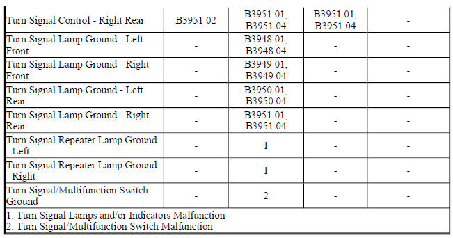
Circuit/System Description
Ground is applied at all times to the turn signal/multifunction switch. The turn signal lamps may only be activated with the ignition switch in the ON or START positions. When the turn signal/multifunction switch is placed in either the turn right or turn left position, ground is applied to the body control module (BCM) through either the right turn or left turn signal switch signal circuit. The BCM responds to the turn signal switch input by applying a pulsating voltage to the front and rear turn signal lamps through there respective control circuits.
When a turn signal request is received by the BCM, a serial data message is sent to the instrument cluster requesting the respective turn signal indicator be pulsed ON and OFF.
Diagnostic Aids
When testing at the turn signal lamp bulb socket, make sure all measurements and test lamp connections are in the correct terminal location and do not come in contact with each other during testing.
Reference Information
Schematic Reference
- Exterior Lights Schematics (Encore) , Exterior Lights Schematics (Encore)
- Body Control System Schematics (Encore) , Body Control System Schematics (Encore)
Connector End View Reference
WIRING SYSTEMS AND POWER MANAGEMENT - COMPONENT CONNECTOR END VIEWS - INDEX - ENCORE WIRING SYSTEMS AND POWER MANAGEMENT - COMPONENT
CONNECTOR END VIEWS - INDEX - Encore
Description and Operation
Exterior Lighting Systems Description and Operation
Electrical Information Reference
- Circuit Testing
- Connector Repairs
- Testing for Intermittent Conditions and Poor Connections
- Wiring Repairs
Scan Tool Reference
Control Module References for scan tool information
Circuit/System Verification
- Ignition ON.
- Verify the scan tool Right Turn Signal Switch and Left Turn Signal Switch parameters change between Active and Inactive while cycling the turn signal switch between the right and left positions.
- If the parameters do not change
Refer to Turn Signal/Multifunction Switch Malfunction.
- If the parameters change
- Verify the left front turn signal lamps turn ON and OFF while commanding the Left Front Turn Signal Lamp ON and OFF with a scan tool.
- If the left front turn signal lamps do not turn ON and OFF
Refer to Turn Signal Lamps Malfunction.
- If the left front turn signal lamps turn ON and OFF
- Verify the right front turn signal lamps turn ON and OFF while commanding the Right Front Turn Signal Lamp ON and OFF with a scan tool.
- If the right front turn signal lamps do not turn ON and OFF
Refer to Turn Signal Lamps Malfunction
- If the right front turn signal lamps turn ON and OFF
- Verify the left rear turn signal lamps turn ON and OFF while commanding the Left Rear Turn Signal Lamp ON and OFF with a scan tool.
- If the left rear turn signal lamps do not turn ON and OFF
Refer to Turn Signal Lamps Malfunction
- If the left rear turn signal lamps turn ON and OFF
- Verify the right rear turn signal lamps turn ON and OFF while commanding the Right Rear Turn Signal Lamp ON and OFF with a scan tool.
- If the right rear turn signal lamps do not turn ON and OFF
Refer to Turn Signal Lamps Malfunction.
- If the right rear turn signal lamps turn ON and OFF
- Verify the left and right turn signal indicators turn ON and OFF while commanding the All Indicators Test ON and OFF with a scan tool.
- If the left or right turn signal indictors do not turn ON and OFF
Refer to Turn Signal Indicators Malfunction
- If the left and right turn signal indictors turn ON and OFF
- All OK.
Circuit/System Testing
Turn Signal/Multifunction Switch Malfunction
- Ignition OFF, scan tool disconnected, all doors closed, all accessories OFF, disconnect the harness connector at the S78 Turn Signal/Multifunction Switch. It may take up to 2 minutes for all vehicle systems to power down.
- Test for less than 15 ohms between the ground circuit terminal 3 and ground.
If 15 ohms or greater
- Ignition OFF.
- Test for less than 2 ohms in the ground circuit end to end.
- If 2 ohms or greater, repair the open/high resistance in the circuit.
- If less than 2 ohms, repair the open/high resistance in the ground connection.
- If less than 15 ohms
- Ignition ON.
- Verify the scan tool Left Turn Signal Switch parameter is Inactive.
- If not Inactive
- Ignition OFF, disconnect the X3 harness connector at the K9 Body Control Module.
- Test for infinite resistance between the signal circuit terminal 1 and ground.
- If less than infinite resistance, repair the short to ground on the circuit.
- If infinite resistance, replace the K9 Body Control Module.
- If Inactive
- Install a 3 A fused jumper wire between the signal circuit terminal 1 and the ground circuit terminal 3.
- Verify the scan tool Left Turn Signal Switch parameter is Active.
- If not Active
- Ignition OFF, disconnect the X3 harness connector at the K9 Body Control Module, ignition ON.
- Test for less than 1 V between the signal circuit terminal 1 and ground.
- If 1 V or greater, repair the short to voltage on the circuit.
- If less than 1 V
- Test for less than 2 ohms in the signal circuit end to end.
- If 2 ohms or greater, repair the open/high resistance in the circuit.
- If less than 2 ohms, replace the K9 Body Control Module.
- If Active
- Verify the scan tool Right Turn Signal Switch parameter is Inactive.
- If not Inactive
- Ignition OFF, disconnect the X3 harness connector at the K9 Body Control Module.
- Test for infinite resistance between the signal circuit terminal 7 and ground.
- If less than infinite resistance, repair the short to ground on the circuit.
- If infinite resistance, replace the K9 Body Control Module.
- If Inactive
- Install a 3 A fused jumper wire between the signal circuit terminal 7 and the ground circuit terminal 3.
- Verify the scan tool Right Turn Signal Switch parameter is Active.
- If not Active
- Ignition OFF, disconnect the X3 harness connector at the K9 Body Control Module, ignition ON.
- Test for less than 1 V between the signal circuit terminal 7 and ground.
- If 1 V or greater, repair the short to voltage on the circuit.
- If less than 1 V
- Test for less than 2 ohms in the signal circuit end to end.
- If 2 ohms or greater, repair the open/high resistance in the circuit.
- If less than 2 ohms, replace the K9 Body Control Module.
- If Active
- Test or replace the S78 Turn Signal/Multifunction Switch.
Turn Signal Lamps Malfunction
- Ignition OFF, exterior lamps OFF, rear hatch latch latched, disconnect the harness connector at the appropriate E4 Turn Signal Lamp.
- Test for less than 5 ohms between the appropriate ground circuit terminal listed below and ground.
- E4LF Turn Signal Lamp - Left Front socket terminal
- E4RF Turn Signal Lamp - Right Front socket terminal
- E4Y Turn Signal Repeater Lamp - Left terminal 1
- E4Z Turn Signal Repeater Lamp - Right terminal 1
- E4LR Turn Signal Lamp - Left Rear socket terminal
- E4RR Turn Signal Lamp - Right Rear socket terminal
- If 5 ohms or greater
- Ignition OFF.
- Test for less than 2 ohms in the ground circuit end to end.
- If 2 ohms or greater, repair the open/high resistance in the circuit.
- If less than 2 ohms, repair the open/high resistance in the ground connection.
- If less than 5 ohms
- Connect a test lamp between the appropriate control circuit terminal listed below and ground.
- E4LF Turn Signal Lamp - Left Front socket terminal
- E4RF Turn Signal Lamp - Right Front socket terminal
- E4Y Turn Signal Repeater Lamp - Left terminal 2
- E4Z Turn Signal Repeater Lamp - Right terminal 2
- E4LR Turn Signal Lamp - Left Rear socket terminal
- E4RR Turn Signal Lamp - Right Rear socket terminal
- Verify the test lamp turns ON and OFF when commanding the appropriate Turn Signal Lamp ON and OFF with a scan tool.
- If the test lamp is always OFF
- Ignition OFF, disconnect the appropriate harness connector listed below at the K9 Body Control Module.
- X5 left turn signals
- X4 right turn signals
- Test for infinite resistance between the control circuit and ground.
- If less than infinite resistance, repair the short to ground on the circuit.
- If infinite resistance
- Test for less than 2 ohms in the control circuit end to end.
- If 2 ohms or greater, repair the open/high resistance in the circuit.
- If less than 2 ohms, replace the K9 Body Control Module.
- If the test lamp is always ON
- Ignition OFF, disconnect the appropriate harness connector listed below at the K9 Body Control Module, ignition ON.
- X5 left turn signals
- X4 right turn signals
- Test for less than 1 V between the control circuit terminal and ground.
- If 1 V or greater, repair the short to voltage on the circuit.
- If less than 1 V, replace the K9 Body Control Module.
- If the test lamp turns ON and OFF
- Test or replace the appropriate E4 Turn Signal Lamp.
Turn Signal Indicators Malfunction
- Ignition ON.
- Verify the left and right turn signal indicators turn ON and OFF while commanding the All Indicators Test ON and OFF with a scan tool.
- If the left or right turn signal indictors are always OFF or remain ON
Replace the P16 Instrument Cluster.
- If the left and right turn signal indictors turn ON and OFF
- Replace the K9 Body Control Module.
Repair Instructions
Perform the Diagnostic Repair Verification after completing the repair.
- Parking and Turn Signal Lamp Bulb Replacement (Left Hand) , Parking and Turn Signal Lamp Bulb Replacement (Right Hand)
- Rear Turn Signal Lamp Bulb Replacement (Encore) , Rear Turn Signal Lamp Bulb Replacement (Encore)
- Turn Signal Switch Replacement (Encore) , Turn Signal Switch Replacement (Encore)
- Front Turn Signal Lamp Bulb Replacement (Left hand) , Front Turn Signal Lamp Bulb Replacement (Right Hand)
- Control Module References for BCM or Instrument Cluster replacement, programming, and setup
READ NEXT:
 Lighting - Repair instructions
Brake pedal position sensor calibration
NOTE:
Brake system does not use a brake switch, stoplight switch or brakelight
switch. System uses a Brake Pedal Position Sensor to control these functions.
Cal
Schematic wiring diagrams
HEADLIGHTS/DAYTIME RUNNING LIGHTS (DRL) WIRING SCHEMATICS (ENCORE)
Controls and Indicators
Fig. 1: Controls and Indicators
HeadLamps
Fig. 2: HeadLamps
Leveling (TR6)
Fig. 3: Leveling (TR6)
HEADL
SEE MORE:
Lumbar Adjustment
If available, press the front or rear of
the switch to increase or decrease
lumbar support. Release the switch
when the desired level of support is
reached.
Reclining Seatbacks
Warning
If either seatback is not locked, it
could move forward in a sudden
stop or crash. That could cause injury to the
Schematic wiring diagrams
SPECIFICATIONS
FASTENER TIGHTENING SPECIFICATIONS
Fastener Tightening Specifications
Adhesives, Fluids, Lubricants, and Sealers
SCHEMATIC WIRING DIAGRAMS
INSIDE REARVIEW MIRROR WIRING SCHEMATICS (ENCORE)
Inside Review Mirror
Fig. 1: Inside Review Mirror
INSIDE REARVIEW MIRROR WIRING SCHEMATICS
