Buick Encore: Repair instructions
Antilock brake system automated bleed
WARNING: Refer to Brake Fluid Irritant Warning .
CAUTION: Refer to Brake Fluid Effects on Paint and Electrical Components Caution .
NOTE: Before performing the Antilock Brake System (ABS) Automated Bleed Procedure, first perform a pressure bleed of the base brake system. Refer to Hydraulic Brake System Bleeding (Manual) , Hydraulic Brake System Bleeding (Pressure) . The automated bleed procedure is recommended when one of the following conditions exists:
- Base brake system bleeding does not achieve the desired pedal height or feel.
- Extreme loss of brake fluid has occurred.
- Air ingestion is suspected in the secondary circuits of the hydraulic brake modulator assembly.
The ABS Automated Bleed Procedure uses a scan tool to cycle the system solenoid valves and run the pump in order to purge any air from the secondary circuits. These circuits are normally closed off and are only opened during system initialization at vehicle start up and during ABS operation. The automated bleed procedure opens these secondary circuits and allows any air trapped in these circuits to flow out toward the brake calipers.
CAUTION: The Auto Bleed Procedure may be terminated at any time during the process by pressing the EXIT button. No further Scan Tool prompts pertaining to the Auto Bleed procedure will be given. After exiting the bleed procedure, relieve bleed pressure and disconnect bleed equipment per manufacturers instructions. Failure to properly relieve pressure may result in spilled brake fluid causing damage to components and painted surfaces.
- Raise and support the vehicle. Refer to Lifting and Jacking the Vehicle .
- Remove all four tire and wheel assemblies. Refer to Tire and Wheel Removal and Installation .
- Inspect the brake system for leaks and visual damage. Refer to Symptoms - Hydraulic Brakes , repair or replace components as needed.
- Lower the vehicle.
- Inspect the battery state of charge. Refer to Battery Inspection/Test .
- Install a scan tool.
- Turn the ignition ON, with the engine OFF.
- With the scan tool, establish communications with the ABS system. Select Control Functions. Select Automated Bleed from the Control Functions menu.
- Raise and support the vehicle. Refer to Lifting and Jacking the Vehicle .
- Following the directions given on the scan tool, pressure bleed the base brake system. Refer to Hydraulic Brake System Bleeding (Manual) , Hydraulic Brake System Bleeding (Pressure) .
- Follow the scan tool directions until the desired brake pedal height is achieved.
- If the bleed procedure is aborted, a malfunction exists. Perform the following steps before resuming the bleed procedure:
- If a DTC is detected, refer to Diagnostic Trouble Code (DTC) List - Vehicle , and diagnose the appropriate DTC.
- If the brake pedal feels spongy, perform the conventional brake bleed procedure again. Refer to Hydraulic Brake System Bleeding (Manual) , Hydraulic Brake System Bleeding (Pressure) .
- When the desired pedal height is achieved, press the brake pedal to inspect for firmness.
- Lower the vehicle.
- Remove the scan tool.
- Install the tire and wheel assemblies. Refer to Tire and Wheel Removal and Installation .
- Inspect the brake fluid level. Refer to Master Cylinder Reservoir Filling .
- Road test the vehicle while inspecting that the pedal remains high and firm.
Steering angle sensor replacement
.gif)
Fig. 7: View Of Steering Angle Sensor
Steering Angle Sensor Replacement
.jpg)
STEERING ANGLE SENSOR CENTERING
The steering angle sensor does not require centering often. Centering of the steering angle sensor might be required after certain service procedures are performed. Some of these procedures are as follows:
- Wheel alignment
- Steering gear replacement
- Steering column replacement
- Collision or other physical damage
- Steering angle sensor replacement
- Electronic brake control module (EBCM) replacement
The steering angle sensor centering procedure can be completed with a scan tool using the following steps:
- Using the steering wheel, align the front wheels forward.
- Apply the parking brake, or set the transmission in the Park.
- Install the scan tool to the data link connector.
- Turn the ignition ON, and the engine OFF.
- Select Steering Wheel Angle Sensor Reset in the Steering Wheel Angle Sensor Module Control Functions list.
- Follow the scan tool directions to complete the reset procedure.
- Select Steering Wheel Angle Sensor Learn in the Steering Wheel Angle Sensor Module Functions list.
- Follow the scan tool directions to complete the learn procedure.
- Clear any DTCs that may be set.
Electronic brake control module replacement
Removal Procedure
WARNING: Refer to Brake Fluid Irritant Warning .
CAUTION: Refer to Brake Fluid Effects on Paint and Electrical Components Caution
- Remove the battery tray. Refer to Battery Tray Replacement .
- Without disconnecting the brake pipes, remove the electronic brake control module (EBCM) with the brake pressure modulator valve (BPMV) and bracket as an assembly. Refer to Brake Pressure Modulator Valve Replacement.
- Carefully position aside the assembly and secure with heavy mechanics wire.
Fig. 8: EBCM Bolts
- Remove the EBCM bolts (1),
.gif)
Fig. 9: Electronic Brake Control Module
NOTE: Do not pry the components apart.
- Carefully separate the EBCM (1) from the BPMV.
- Clean the sealing surfaces of the EBCM and the BPMV with denatured alcohol and allow to dry.
Installation Procedure
.gif)
Fig. 10: Electronic Brake Control Module
- Install the EBCM (1) to the BPMV.
.gif)
Fig. 11: EBCM Bolts
CAUTION: Refer to Fastener Caution .
- Install the EBCM bolts (1) and tighten to 3 N.m (26 lb in).
- Install the BPMV with EBCM and bracket assembly. Refer to Brake Pressure Modulator Valve Replacement.
- Install the battery tray. Refer to Battery Tray Replacement .
- Program the EBCM. Refer to Electronic Brake Control Module Programming and Setup .
Brake pressure modulator valve replacement
Removal Procedure
WARNING: Refer to Brake Fluid Irritant Warning .
CAUTION: Refer to Brake Fluid Effects on Paint and Electrical Components Caution .
CAUTION: Always connect or disconnect the wiring harness connector from the EBCM/EBTCM with the ignition switch in the OFF position. Failure to observe this precaution could result in damage to the EBCM/EBTCM.
- Place the ignition switch in the OFF position.
- Remove the battery tray. Refer to Battery Tray Replacement .
NOTE: The area around the electronic brake control module (EBCM) and brake pressure modulator valve (BPMV) assembly must be free from loose dirt to prevent contamination of disassembled ABS components.
- Clean the area surrounding the EBCM/BPMV assembly of any accumulated dirt and debris.
- Disconnect the EBCM electrical connector.
.gif)
Fig. 12: Master Cylinder Secondary Brake Pipe Fitting
- Disconnect the master cylinder secondary brake pipe fitting (1) from the BPMV.
- Cap the brake pipe fitting and plug the BPMV inlet port to prevent brake fluid loss and contamination.
.gif)
Fig. 13: Master Cylinder Primary Brake Pipe Fitting
- Disconnect the master cylinder primary brake pipe fitting (1) from the BPMV.
- Cap the brake pipe fitting and plug the BPMV inlet port to prevent brake fluid loss and contamination.
Fig. 14: Front And Rear Brake Pipe Fittings
- Reference mark the BPMV outlet brake pipe fittings (1) and disconnect the fittings.
- Cap the brake pipe fittings and plug the BPMV outlet ports to prevent brake fluid loss and contamination.
Fig. 15: BPMV Bracket Nut Protective Caps
- Remove the protective caps (1) from the BPMV bracket nuts.
Fig. 16: Electronic Brake Control Module And Bracket Assembly Nuts
- Remove the EBCM/BPMV and bracket assembly nuts (1).
- Remove the EBCM/BPMV and bracket assembly from the vehicle.
Fig. 17: Brake Pressure Modulator Valve Bolts
- Remove the BPMV bolts (1).
- Remove the BPMV bracket.
- If installing a new BPMV, remove the EBCM. Refer to Electronic Brake Control Module Replacement.
Installation Procedure
- If installing a new BPMV, install the EBCM. Refer to Electronic Brake Control Module Replacement.
- Install the BPMV bracket to the BPMV.
Fig. 18: Brake Pressure Modulator Valve Bolts
CAUTION: Refer to Fastener Caution .
- Install the BPMV bolts (1) and tighten to 11 N.m (97 lb in).
Fig. 19: Electronic Brake Control Module And Bracket Assembly Nuts
- Install the EBCM/BPMV and bracket assembly to the vehicle.
- Install the EBCM/BPMV and bracket assembly nuts (1) and tighten to 17 N.m (12 lb ft).
Fig. 20: BPMV Bracket Nut Protective Caps
- Install the protective caps (1) to the BPMV bracket nuts.
Fig. 21: Front And Rear Brake Pipe Fittings
NOTE: Install the brake pipes in the same locations referenced during removal.
- Install the BPMV outlet brake pipe fittings (1) to the BPMV outlet ports.
- Connect the brake pipe fittings and tighten to 18 N.m (13 lb ft).
Fig. 22: Master Cylinder Primary Brake Pipe Fitting
- Connect the master cylinder primary brake pipe fitting (1) to the BPMV and tighten to 18 N.m (13 lb ft)
Fig. 23: Master Cylinder Secondary Brake Pipe Fitting
- Connect the master cylinder secondary brake pipe fitting (1) to the BPMV and tighten to 18 N.m (13 lb ft).
- Connect the EBCM electrical connector.
- Install the battery tray. Refer to Battery Tray Replacement .
- Bleed the hydraulic brake system. Refer to Hydraulic Brake System Bleeding (Manual) , Hydraulic Brake System Bleeding (Pressure) .
- Perform the Diagnostic System Check - Vehicle .
- Observe the brake pedal feel after performing the diagnostic system check. If the pedal now feels spongy, air may have been in the secondary hydraulic circuit of the brake modulator which may have been introduced into the primary circuit. If the pedal feels spongy, bleed the antilock brake system. Refer to Antilock Brake System Automated Bleed.
Brake pressure modulator valve bracket replacement
Removal Procedure
- Remove the brake pressure modulator valve (BPMV) and bracket assembly. Refer to Brake Pressure Modulator Valve Replacement.
Fig. 24: Brake Pressure Modulator Valve Bolts
- Remove the BPMV bolts (1).
- Remove the BPMV bracket.
Installation Procedure
- Install the BPMV bracket to the BPMV.
Fig. 25: Brake Pressure Modulator Valve Bolts
CAUTION: Refer to Fastener Caution .
- Install the BPMV bolts (1) and tighten to 11 N.m (97 lb in).
- Install the BPMV and bracket assembly. Refer to Brake Pressure Modulator Valve Replacement.
FRONT WHEEL SPEED SENSOR REPLACEMENT
Removal Procedure
WARNING: Refer to Brake Dust Warning .
- Raise and support the vehicle. Refer to Lifting and Jacking the Vehicle .
- Remove the tire and wheel assembly. Refer to Tire and Wheel Removal and Installation .
- Clean the wheel speed sensor mounting area on the steering knuckle of any accumulated dirt and debris.
Fig. 26: Wheel Speed Sensor Electrical Connector
- Disconnect the wheel speed sensor electrical connector (1) and release the connector from the vehicle body.
Fig. 27: Wheel Speed Sensor Harness Grommets
- Release the wheel speed sensor harness grommets (1) from the brake hose brackets.
Fig. 28: Wheel Speed Sensor Bolt
- Remove the wheel speed sensor bolt (1).
Fig. 29: Wheel Speed Sensor
- Carefully remove the wheel speed sensor (1) from the steering knuckle by pulling the sensor straight upward using a slight twisting motion.
Installation Procedure
Fig. 30: Wheel Speed Sensor
- Install the wheel speed sensor (1) to the steering knuckle.
Fig. 31: Wheel Speed Sensor Bolt
CAUTION: Refer to Fastener Caution .
- Install the wheel speed sensor bolt (1) and tighten to 8 N.m (71 lb in).
Fig. 32: Wheel Speed Sensor Harness Grommets
- Install the wheel speed sensor harness grommets (1) to the brake hose brackets.
Fig. 33: Wheel Speed Sensor Electrical Connector
- Connect the wheel speed sensor electrical connector (1) and install the connector to the vehicle body.
- Install the tire and wheel assembly. Refer to Tire and Wheel Removal and Installation .
- Perform the diagnostic system check. Refer to Diagnostic System Check - Vehicle .
Rear wheel speed sensor replacement
Removal Procedure
WARNING: Refer to Brake Dust Warning .
- Raise and support the vehicle. Refer to Lifting and Jacking the Vehicle .
- Remove the tire and wheel assembly. Refer to Tire and Wheel Removal and Installation .
- Remove the rear wheelhouse panel liner. Refer to Rear Wheelhouse Liner Replacement .
Fig. 34: Wheel Speed Sensor Electrical Connector
- Disconnect the wheel speed sensor electrical connector (1) and release the connector clip from the wheelhouse bracket.
- Release the wheel speed sensor harness clip (2) from the wheelhouse panel.
Fig. 35: Wheel Speed Sensor Harness Clips
- Release the wheel speed sensor harness clips (1) from the rear axle.
Fig. 36: Wheel Speed Sensor Bolt
- Remove the wheel speed sensor bolt (1).
Fig. 37: Wheel Speed Sensor
- Remove the wheel speed sensor (1) from the rear suspension knuckle.
Installation Procedure
Fig. 38: Wheel Speed Sensor
- Install the wheel speed sensor (1) to the rear suspension knuckle.
Fig. 39: Wheel Speed Sensor Bolt
CAUTION: Refer to Fastener Caution .
- Install the wheel speed sensor bolt (1) and tighten to 8 N.m (71 lb in).
Fig. 40: Wheel Speed Sensor Harness Clips
- Install the wheel speed sensor harness clips (1) to the rear axle.
Fig. 41: Wheel Speed Sensor Electrical Connector
- Connect the wheel speed sensor electrical connector (1) and install the connector clip to the wheelhouse bracket.
- Install the wheel speed sensor harness clip (2) to the wheelhouse panel.
- Install the rear wheelhouse panel liner. Refer to Rear Wheelhouse Liner Replacement .
- Install the tire and wheel assembly. Refer to Tire and Wheel Removal and Installation .
- Perform the diagnostic system check. Refer to Diagnostic System Check - Vehicle .
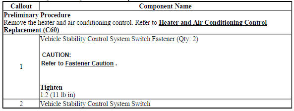
Vehicle stability control system switch replacement
Fig. 42: Vehicle Stability Control System Switch
Vehicle Stability Control System Switch Replacement
VEHICLE YAW SENSOR LEARN
The yaw rate sensor learn procedure can be completed with a scan tool using the following steps:
- Place vehicle on a level surface
- Apply the parking brake, or set the transmission in the P position.
- Install the scan tool to the data link connector.
- Ignition ON, engine OFF.
- Select Yaw Rate Sensor Learn in the Electronic Brake Control Module Configuration/Reset Functions list.
- Follow the scan tool directions to complete the calibration procedure.
- Clear any DTCs that may be set.
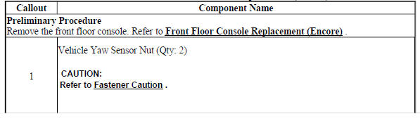
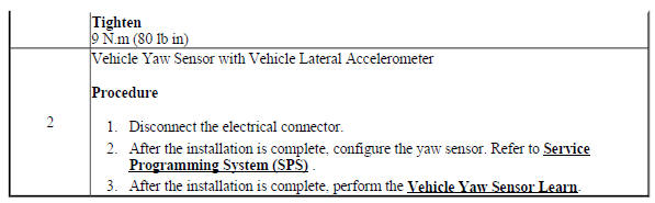
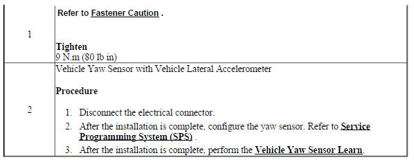
VEHICLE YAW SENSOR WITH VEHICLE LATERAL ACCELEROMETER REPLACEMENT (ENCORE)
Fig. 43: Vehicle Yaw Sensor with Vehicle Lateral Accelerometer
Vehicle Yaw Sensor with Vehicle Lateral Accelerometer Replacement (Encore)
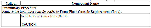
VEHICLE YAW SENSOR WITH VEHICLE LATERAL ACCELEROMETER REPLACEMENT (Encore)
Fig. 44: Vehicle Yaw Sensor with Vehicle Lateral Accelerometer
Vehicle Yaw Sensor with Vehicle Lateral Accelerometer Replacement (Encore)
READ NEXT:
 Description and operation
ABS DESCRIPTION AND OPERATION
Antilock Brake System Block Diagram
Fig. 45: Antilock Brake System Block Diagram
This vehicle is equipped with the MGH 60 Mando electronic stability control
brake
Diagnostic information and procedures
Brake rotor thickness measurement
SPECIFICATIONS
FASTENER TIGHTENING SPECIFICATIONS
Fastener Tightening Specifications
DISC BRAKE COMPONENT SPECIFICATIONS
Disc Brake Component Specifications
DIA
SEE MORE:
Programming and Setup - All ASystems
Diagnostic information and procedures
CONTROL MODULE REFERENCES
Reference Information
Data Link References
Diagnostic System Check - Vehicle
Diagnostic Trouble Code (DTC) List - Vehicle
Symptoms - Vehicle
Control Module References
Schematic wiring diagrams
SPECIFICATIONS
Fastener Tightening Specifications
SCHEMATIC WIRING DIAGRAMS
SIR WIRING SCHEMATICS (ENCORE)
Power, Ground, Passenger Presence, Serial Data and Indicators
Fig. 1: Power, Ground, Passenger Presence, Serial Data and Indicators
Front Air Bags, and Impact Sensors (AY0 or AYF)
Fig. 2:
