Buick Encore: Schematic wiring diagrams
SPECIFICATIONS
FASTENER TIGHTENING SPECIFICATIONS
Fastener Tightening Specifications
.jpg)
SCHEMATIC WIRING DIAGRAMS
ANTILOCK BRAKE SYSTEM WIRING SCHEMATICS (ENCORE)
Module Power, Ground and Subsystem References
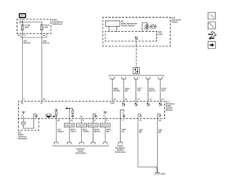
Fig. 1: Module Power, Ground and Subsystem References
Wheel Speed Sensors

Fig. 2: Wheel Speed Sensors
Stability Control
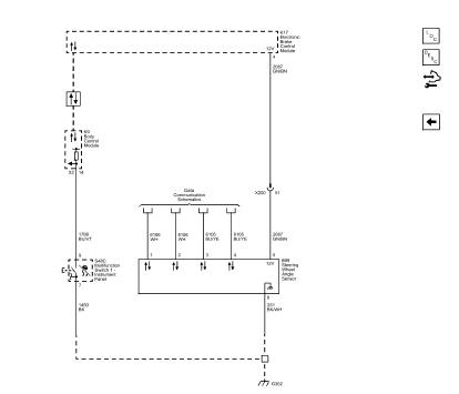
Fig. 3: Stability Control
ANTILOCK BRAKE SYSTEM WIRING SCHEMATICS (Encore)
Module Power, Ground and Subsystem References

Fig. 4: Module Power, Ground and Subsystem References
Wheel Speed Sensors

Fig. 5: Wheel Speed Sensors
Stability Control

Fig. 6: Stability Control
READ NEXT:
 Diagnostic information and procedures
DTC B2745 (WITH C67/CJ2): Traction control switch
DIAGNOSTIC CODE INDEX
DTC B2745 (WITH C67/CJ2): Traction control switch
Diagnostic Instructions
Perform the Diagnostic System Check - Vehicle
Repair instructions
Antilock brake system automated bleed
WARNING: Refer to Brake Fluid Irritant Warning .
CAUTION: Refer to Brake Fluid Effects on Paint and Electrical
Components Caution .
NOTE: Before performing the A
Description and operation
ABS DESCRIPTION AND OPERATION
Antilock Brake System Block Diagram
Fig. 45: Antilock Brake System Block Diagram
This vehicle is equipped with the MGH 60 Mando electronic stability control
brake
SEE MORE:
Air & Wind Noise - Diagnostic information and procedures
AIR/WIND NOISE
Special Tools
CH-39570 Chassis Ear
GE-41416 Ultrasonic Leak Detector
WARNING: An assistant should drive the vehicle while the technician
checks for the
location of the reported condition. Otherwise, personal injury could
result.
To analyze a reported windnoise condition, test dri
Engine Exhaust
Warning
Engine exhaust contains carbon
monoxide (CO), which cannot be
seen or smelled. Exposure to CO
can cause unconsciousness and
even death.
Exhaust may enter the vehicle if:
The vehicle idles in areas
with poor ventilation
(parking garages, tunnels,
deep snow that may block
underbody airf
© 2020-2025 Copyright www.bencore2.com
