Buick Encore: Diagnostic information and procedures
DTC P0601, P0603, P0604, OR P062F: Control module memory
Diagnostic Instructions
- Perform the Diagnostic System Check - Vehicle prior to using this diagnostic procedure.
- Review Strategy Based Diagnosis for an overview of the diagnostic approach.
- Diagnostic Procedure Instructions provides an overview of each diagnostic category.
DTC Descriptors
NOTE: DTCs P0601, P0603, P0604 or P062F could set in other control modules. Verify the DTCs are set in the transmission control module (TCM).
DTC P0601
Control Module Read Only Memory Performance
DTC P0603
Control Module Long Term Memory Reset
DTC P0604
Control Module Random Access Memory Performance
DTC P062F
Control Module Long Term Memory Performance
Circuit/System Description
This is an internal fault detection of the transmission control module (TCM), which is part of the control solenoid valve assembly. This fault is handled inside the TCM and no external circuits are involved.
Conditions for Running the DTC
P0601 or P0604
Runs continuously when TCM is powered up.
P0603
One time at TCM power up.
P062F
One time at TCM power down.
Conditions for Setting the DTC
P0601
TCM has detected a read only memory (ROM) checksum error 5 times.
P0603
TCM has detected a non-volatile memory checksum error at TCM powerup.
P0604
TCM has detected a random access memory (RAM) test error 5 times.
P062F
TCM has detected a non-volatile memory error during power-down.
Action Taken When the DTC Sets
- P0601, P0603, P0604, and P062F are Type A DTCs.
- TCM commands maximum line pressure.
- TCM forces the torque converter clutch (TCC) OFF.
- TCM inhibits TCC engagement.
- TCM freezes transmission adaptive functions.
- TCM commands the high side driver OFF.
- TCM defaults the transmission to 4th gear and reverse.
- Torque management is enabled.
- TCM inhibits neutral idle.
- TCM inhibits Tap Up/Down function.
- TCM inhibits manual shifting of forward gears.
Conditions for Clearing the DTC
P0601, P0603, P0604, and P062F are Type A DTCs.
Reference Information
Schematic Reference
Automatic Transmission Controls Schematics (Encore, MH8 or MHB) , Automatic Transmission Controls Schematics (Encore, MH8 or MHB)
- Connector End View Reference
- WIRING SYSTEMS AND POWER MANAGEMENT - COMPONENT CONNECTOR END VIEWS - INDEX - ENCORE WIRING SYSTEMS AND POWER MANAGEMENT - COMPONENT CONNECTOR END VIEWS - INDEX - Encore
- Inline Harness Connector End Views (Encore) , Inline Harness Connector End Views (Encore)
Description and Operation
- Electronic Component Description
- Transmission Component and System Description
- Transmission General Description
Electrical Information Reference
- Circuit Testing
- Connector Repairs
- Testing for Intermittent Conditions and Poor Connections
- Wiring Repairs
DTC Type Reference
Powertrain Diagnostic Trouble Code (DTC) Type Definitions (LUV) , Powertrain Diagnostic Trouble Code (DTC) Type Definitions (2H0)
Scan Tool Reference
Control Module References for scan tool information
Circuit/System Verification
CAUTION: Before programming a control module, the following must be observed, or control module damage may occur:
- The TIS terminal, MDI, and/or scan tool must have the latest software.
- The vehicle battery must be fully charged. The battery voltage should be between 12-14 volts.
- The TIS terminal, MDI, and/or scan tool connections must be secure.
- A battery charger must NOT be connected to the battery when programming a control module.
- Ignition OFF and all vehicle systems OFF. It may take up to 2 min for all vehicle systems to power down.
- Ignition ON.
- Verify that DTC P0601, P0603, P0604, or P062F is not set.
If any of the DTCs are set
Replace the Q8 Control Solenoid Valve Assembly.
If none of the DTCs are set
- Operate the vehicle within the Conditions for Running the DTC. You may also operate the vehicle within the conditions that you observed from the Freeze Frame/Failure Records data.
- Verify the DTC does not set.
If the DTC sets
Replace the Q8 Control Solenoid Valve Assembly.
If the DTC does not set
- All OK.
Repair Instructions
Perform the Diagnostic Repair Verification after completing the repair.
- Perform the Transmission Adaptive Values Learn following all transmission repairs
- Control Module References for Control Solenoid Valve Assembly replacement, programming and setup
DTC P0634
Diagnostic Instructions
- Perform the Diagnostic System Check - Vehicle prior to using this diagnostic procedure.
- Review Strategy Based Diagnosis for an overview of the diagnostic approach.
- Diagnostic Procedure Instructions provides an overview of each diagnostic category.
DTC Descriptor
DTC P0634
Control Module Overtemperature
Circuit/System Description
The transmission control module (TCM) temperature sensor is located inside of the control solenoid valve assembly which has no serviceable components. The TCM monitors the TCM temperature sensor for over temperature protection.
Conditions for Running the DTC
- DTC P0634 is not set.
- TCM temperature is between 0-240ºC (32-464ºF) for 0.25 s.
- Ignition voltage is 9-32 V.
- DTC runs continuously when above conditions are met.
Conditions for Setting the DTC
Condition 1
TCM has detected an internal temperature condition of 144ºC (291ºF) or greater for 5 s.
Condition 2
Ignition voltage is 18 V or greater and the TCM temperature is 50ºC (122ºF) or greater for 2 s.
Action Taken When the DTC Sets
- P0634 is a Type A DTC.
- TCM limits the transmission to 4th gear and reverse.
- TCM inhibits Tap Up/Down function.
- TCM inhibits manual shifting of forward gears.
- TCM enables torque management.
- TCM shuts down.
- TCM commands maximum line pressure.
Conditions for Clearing the DTC
P0634 is a Type A DTC.
Diagnostic Aids
During a road test, the TCM temperature should steadily increase to a normal operating temperature, and then stabilize.
Reference Information
Schematic Reference
Automatic Transmission Controls Schematics (Encore, MH8 or MHB) , Automatic Transmission Controls Schematics (Encore, MH8 or MHB)
Connector End View Reference
WIRING SYSTEMS AND POWER MANAGEMENT - COMPONENT CONNECTOR END VIEWS - INDEX - ENCORE WIRING SYSTEMS AND POWER MANAGEMENT - COMPONENT CONNECTOR END VIEWS - INDEX - Encore
Description and Operation
- Electronic Component Description
- Transmission Component and System Description
- Transmission General Description
Electrical Information Reference
- Circuit Testing
- Connector Repairs
- Testing for Intermittent Conditions and Poor Connections
- Wiring Repairs
DTC Type Reference
Powertrain Diagnostic Trouble Code (DTC) Type Definitions (LUV) , Powertrain Diagnostic Trouble Code (DTC) Type Definitions (2H0)
Scan Tool Reference
Control Module References for scan tool information
Circuit/System Verification
- Ignition ON.
- Verify the scan tool Engine Coolant Temperature parameter was less than 125ºC (257ºF) when DTC set by reviewing the scan tool Freeze Frame/Failure Records.
If 125ºC (257ºF) or greater
Refer to Engine Overheating .
If less than 125ºC (257ºF)
- Verify the scan tool TCM Temperature parameter is less than 146ºC (295ºF).
If 146ºC (295ºF) or greater
Replace the Q8 Control Solenoid Valve assembly.
If less than 146ºC (295ºF)
- Verify the transmission fluid level and condition is correct. Refer to Transmission Fluid Level and Condition Check.
- If the transmission fluid level and condition is not correct
Repair as necessary.
If the transmission fluid level and condition is correct
- Clear the TCM DTCs with a scan tool.
- Operate the vehicle until normal engine temperature is reached.
- Verify the scan tool Transmission Fluid Temperature parameter is less than 140ºC (284ºF).
If 140ºC (284ºF) or greater
- Ignition OFF.
- Verify the conditions listed below do not exist:
- Obstructions to the airflow to the radiator or transmission
- Radiator damage
- Transmission cooler damage
- Transmission cooler pipe kinked or damaged
If a condition exists, repair or replace as necessary.
If none of the conditions exist, refer to Transmission Fluid Cooler Flushing and Flow Test .
If less than 140ºC (284ºF)
- Operate the vehicle within the Conditions for Running the DTC. You may also operate the vehicle within the conditions that you observed from the Freeze Frame/Failure Records data.
- Verify the DTC does not set.
If the DTC sets
Replace the Q8 Control Solenoid Valve Assembly.
If the DTC does not set
- All OK.
Repair Instructions
Perform the Diagnostic Repair Verification after completing the repair.
- Perform the Transmission Adaptive Values Learn following all transmission repairs
- Transmission Fluid Cooler Hose/Pipe Quick-Connect Fitting Disconnection and Connection
- Transmission Fluid Cooler Inlet Pipe Replacement
- Transmission Fluid Cooler Outlet Pipe Replacement
- Control Module References for Control Solenoid Valve Assembly replacement, programming and setup
DTC P0658 OR P0659
Diagnostic Instructions
- Perform the Diagnostic System Check - Vehicle prior to using this diagnostic procedure.
- Review Strategy Based Diagnosis for an overview of the diagnostic approach.
- Diagnostic Procedure Instructions provides an overview of each diagnostic category.
DTC Descriptors
DTC P0658
Actuator High Control Circuit Group 1 Low Voltage
DTC P0659
Actuator High Control Circuit Group 1 High Voltage
Circuit/System Description
The transmission control module (TCM) high side driver 1 is located inside the control solenoid valve assembly which has no serviceable components. The high side driver 1 provides power to the pressure control solenoid valves and shift solenoid valves.
Conditions for Running the DTC
P0658
- DTC P0658 is not set.
- High side driver 1 is enabled.
- Runs continuously when above conditions are met.
P0659
- DTC P0659 is not set.
- Runs one time when ignition transitions from OFF to ON.
Conditions for Setting the DTC
P0658
TCM detects an internal open or short to ground in the high side driver 1 circuit for 1 s.
P0659
TCM detects an internal short to voltage on the high side driver 1 circuit for 1 s.
Action Taken When the DTC Sets
P0658
- P0658 is a Type A DTC.
- TCM turns the high side driver OFF.
- TCM commands all solenoids OFF.
- TCM commands the TCC OFF.
- TCM commands maximum line pressure.
- TCM freezes transmission adaptive functions.
- TCM inhibits neutral idle.
- TCM inhibits the Tap Up/Tap Down function.
- TCM inhibits manual shifting of forward gears.
- TCM defaults the transmission to 4th gear and reverse.
- TCM enables torque management.
P0659
P0659 is a Type C DTC.
Conditions for Clearing the DTC
- P0658 is a Type A DTC.
- P0659 is a Type C DTC.
Reference Information
Schematic Reference
Automatic Transmission Controls Schematics (Encore, MH8 or MHB) , Automatic Transmission Controls Schematics (Encore, MH8 or MHB)
Connector End View Reference
WIRING SYSTEMS AND POWER MANAGEMENT - COMPONENT CONNECTOR END VIEWS - INDEX - ENCORE WIRING SYSTEMS AND POWER MANAGEMENT - COMPONENT CONNECTOR END VIEWS - INDEX - Encore
Description and Operation
- Electronic Component Description
- Transmission Component and System Description
- Transmission General Description
Electrical Information Reference
- Circuit Testing
- Connector Repairs
- Testing for Intermittent Conditions and Poor Connections
- Wiring Repairs
DTC Type Reference
Powertrain Diagnostic Trouble Code (DTC) Type Definitions (LUV) , Powertrain Diagnostic Trouble Code (DTC) Type Definitions (2H0)
Scan Tool Reference
Control Module References for scan tool information
Special Tools
DT-48616-10 Adapter Harness
For equivalent regional tools, refer to Special Tools .
Circuit/System Verification
- Ignition ON.
- Verify the scan tool High Side Driver 1 parameter displays ON.
If ON is not displayed
Refer to Circuit/System Testing.
If ON is displayed
- Engine Running and the gear selector lever in the Park position.
- Verify the scan tool parameters listed below do not display Malfunction:
- High Side Driver 1 Circuit Low Voltage Test Status
- High Side Driver 1 Circuit Open Test Status
- High Side Driver 1 Circuit High Voltage Test Status
If Malfunction is displayed
Refer to Circuit/System Testing.
If Malfunction is not displayed
- Operate the vehicle within the Conditions for Running the DTC. You may also operate the vehicle within the conditions that you observed from the Freeze Frame/Failure Records data.
- Verify the DTC does not set.
If the DTC sets
Refer to Circuit/System Testing.
If the DTC does not set
- All OK.
Circuit/System Testing
NOTE: You must perform the Circuit/System Verification first.
- Ignition OFF, remove the Q8 Control Solenoid Valve Assembly.
- Verify the Q8 Control Solenoid Valve Assembly is not contaminated with any debris. Refer to Control Solenoid Valve and Transmission Control Module Assembly Inspection.
If contaminated
Repair as necessary.
If not contaminated
- Verify the resistance is within the specified range for each solenoid listed in the Control Solenoid Valve and Transmission Control Module Assembly Inspection.
If the resistance is not within range
Replace the Q8 Control Solenoid Valve Assembly.
If the resistance is within range
- Place the Q8 Control Solenoid Valve Assembly on a clean work surface near the transmission assembly.
- Connect the DT-48616-10 adapter harness between the vehicle harness connector, and the Q8 Control Solenoid Valve Assembly connector. Ignition ON.
- Verify the scan tool parameters listed below do not display Malfunction:
- High Side Driver 1 Circuit Low Voltage Test Status
- High Side Driver 1 Circuit Open Test Status
- High Side Driver 1 Circuit High Voltage Test Status
If Malfunction is displayed
Replace the Q8 Control Solenoid Valve Assembly.
If Malfunction is not displayed
- All OK.
Repair Instructions
Perform the Diagnostic Repair Verification after completing the repair.
- Perform the Transmission Adaptive Values Learn following all transmission repairs
- Control Module References - for Control Solenoid Valve Assembly replacement, programming and setup
DTC P0667, P0668, OR P0669
Diagnostic Instructions
- Perform the Diagnostic System Check - Vehicle prior to using this diagnostic procedure.
- Review Strategy Based Diagnosis for an overview of the diagnostic approach.
- Diagnostic Procedure Instructions provides an overview of each diagnostic category.
DTC Descriptors
DTC P0667
Control Module Temperature Sensor Performance
DTC P0668
Control Module Temperature Sensor Circuit Low Voltage
DTC P0669
Control Module Temperature Sensor Circuit High Voltage
Circuit/System Description
The transmission control module (TCM) temperature sensor is located inside of the control solenoid valve assembly which has no serviceable components. The TCM temperature sensor provides the temperature of the TCM. This temperature reading is used in various shifting and diagnostic routines in the TCM software. This fault is handled inside the TCM and no external circuits are involved.
Conditions for Running the DTC
P0667
- DTC P0101, P0102, P0103, P0106, P0107, P0108, P0171, P0172, P0174, P0175, P0201, P0202, P0203, P0204, P0205, P0206, P0207, P0208, P0300, P0301, P0302, P0303, P0304, P0305, P0306, P0307, P0308, P0401, P042E, P0658, P0667, P0668, P0669, P06AD, P06AE, P0712, P0713, P0716, P0717, P0722, P0723, P0962, P0963, P0966, P0967, P0970, P0971, P215C, P2720, P2721, P2729, or P2730 is not set.
- Engine torque signal is valid.
- Ignition voltage is 9-32 V.
- Engine speed is 400-7,500 RPM for 5 s.
- Throttle position signal is valid.
- Runs continuously when above conditions are met.
P0668
- DTC P0668 is not set.
- Ignition voltage is 9-32 V.
- Engine speed is 400-7,500 RPM for 5 s.
- Runs continuously when above conditions are met.
P0669
- DTC P0669, P0716, P0717, P0722, or P0723 is not set.
- Ignition voltage is 9-32 V.
- Engine speed is 400-7,500 RPM for 5 s.
- Runs continuously when above conditions are met.
Conditions for Setting the DTC
P0667
- TCM detects a 20-50ºC (36-90ºF) or greater difference between the transmission fluid temperature and TCM substrate temperature, which depends on the average of the transmission fluid temperature, TCM substrate temperature, and TCM power up temperature.
- TCM detects a 8-10ºC (14-18ºF) or greater difference between the TCM power up temperature and TCM substrate temperature, which depends on the average of the transmission fluid temperature, TCM substrate temperature, and TCM power up temperature.
- Above conditions have to be met for 5 min within a 6 min period.
P0668
TCM internal temperature is 254ºC (489ºF) or greater for 1 min.
P0669
TCM internal temperature is -254ºC (-425ºF) or less for 1 min.
Action Taken When the DTC Sets
- P0667, P0668, and P0669 are Type B DTCs.
- TCM defaults the TCM substrate temperature to a calculated temperature based on the TCM power up temperature.
Conditions for Clearing the DTC
P0667, P0668, and P0669 are Type B DTCs.
Diagnostic Aids
The TCM temperature sensor is located inside of the control solenoid valve assembly and its output should resemble that of the transmission fluid temperature sensor output. During a road test, the TCM temperature should steadily increase to a normal operating temperature, and then stabilize.
Reference Information
Schematic Reference
Automatic Transmission Controls Schematics (Encore, MH8 or MHB) , Automatic Transmission Controls Schematics (Encore, MH8 or MHB)
Connector End View Reference
WIRING SYSTEMS AND POWER MANAGEMENT - COMPONENT CONNECTOR END VIEWS - INDEX - ENCORE WIRING SYSTEMS AND POWER MANAGEMENT - COMPONENT CONNECTOR END VIEWS - INDEX - Encore
- Inline Harness Connector End Views (Encore) , Inline Harness Connector End Views (Encore)
Description and Operation
- Electronic Component Description
- Transmission Component and System Description
- Transmission General Description
Electrical Information Reference
- Circuit Testing
- Connector Repairs
- Testing for Intermittent Conditions and Poor Connections
- Wiring Repairs
DTC Type Reference
Powertrain Diagnostic Trouble Code (DTC) Type Definitions (LUV) , Powertrain Diagnostic Trouble Code (DTC) Type Definitions (2H0)
Scan Tool Reference
Control Module References for scan tool information
Circuit/System Verification
- Ignition ON.
- Verify the scan tool TCM Temperature parameter is between -254 and +254ºC (-425 and +489ºF).
If not between -254 and +254ºC (-425 and +489ºF)
Replace the Q8 Control Solenoid Valve Assembly.
If between -254 and +254ºC (-425 and +489ºF)
- Verify the scan tool TCM Temperature parameter increases greater than 2ºC (3.6ºF) after operating the vehicle at 64 km/h (40 mph) for 10 min.
If the temperature does not increase greater than 2ºC (3.6ºF)
Replace the Q8 Control Solenoid Valve Assembly.
If the temperature increases greater than 2ºC (3.6ºF)
- Verify the scan tool Transmission Fluid Temperature and TCM Temperature parameters are within 20ºC (36ºF) of each other.
If the temperatures are not within 20ºC (36ºF)
Replace the Q8 Control Solenoid Valve Assembly.
If the temperatures are within 20ºC (36ºF)
- Operate the vehicle within the Conditions for Running the DTC. You may also operate the vehicle within the conditions that you observed from the Freeze Frame/Failure Records data.
- Verify the DTC does not set.
If the DTC sets
Replace the Q8 Control Solenoid Valve Assembly.
If the DTC does not set
- All OK.
Repair Instructions
Perform the Diagnostic Repair Verification after completing the repair.
- Perform the Transmission Adaptive Values Learn following all transmission repairs
- Control Module References - for Control Solenoid Valve Assembly replacement, programming and setup
DTC P06AC, P06AD, OR P06AE
Diagnostic Instructions
- Perform the Diagnostic System Check - Vehicle prior to using this diagnostic procedure.
- Review Strategy Based Diagnosis for an overview of the diagnostic approach.
- Diagnostic Procedure Instructions provides an overview of each diagnostic category.
DTC Descriptors
DTC P06AC
Control Module Power Up Temperature Sensor Performance
DTC P06AD
Control Module Power Up Temperature Sensor Circuit Low Voltage
DTC P06AE
Control Module Power Up Temperature Sensor Circuit High Voltage
Circuit/System Description
The transmission control module (TCM) power up temperature sensor is located inside of the Control Solenoid Valve Assembly which has no serviceable components. The TCM power up temperature sensor provides the temperature of the TCM when the TCM power is on. This temperature reading is used in various shifting and diagnostic routines in the TCM software. This fault is handled inside the TCM and no external circuits are involved.
Conditions for Running the DTC
P06AC
- DTC P0101, P0102, P0103, P0106, P0107, P0108, P0171, P0172, P0174, P0175, P0201, P0202, P0203, P0204, P0205, P0206, P0207, P0208, P0300, P0301, P0302, P0303, P0304, P0305, P0306, P0307, P0308, P0401, P042E, P0658, P0668, P0669, P06AC, P06AD, P06AE, P0712, P0713, P0716, P0717, P0722, P0723, P0962, P0963, P0966, P0967, P0970, P0971, P215C, P2720, P2721, P2729, or P2730 is not set.
- Throttle position signal is valid.
- Engine speed is 400-7,500 RPM for 5 s.
- Ignition voltage is 9-32 V.
- Engine torque signal is valid.
- DTC runs continuously when the above conditions are met.
P06AD
- DTC P06AD, P0716, P0717, P0722, or P0723 is not set.
- Engine speed is 400-7,500 RPM for 5 s.
- Ignition voltage is 9-32 V.
- DTC runs continuously when the above conditions are met.
P06AE
- DTC P06AE is not set.
- Engine speed is 400-7,500 RPM for 5 s.
- Ignition voltage is 9-32 V.
- DTC runs continuously when the above conditions are met.
Conditions for Setting the DTC
P06AC
- TCM detects a 20-50ºC (36-90ºF), or greater difference between the transmission fluid temperature and TCM power up temperature, which depends on the average of transmission fluid temperature, TCM substrate temperature, and TCM power up temperature.
- TCM detects an 8-10ºC (14-18ºF), or greater difference between the TCM substrate temperature and TCM power up temperature, which depends on the average of the transmission fluid temperature, TCM substrate temperature, and TCM power up temperature.
- Above conditions have to be met for 5 min within a 6 min period.
P06AD
TCM power up temperature is -254ºC (-425ºF) or less for 1 min.
P06AE
TCM power up temperature is 254ºC (489ºF) or greater for 1 min.
Action Taken When the DTC Sets
- P06AC, P06AD, and P06AE are Type B DTCs.
- TCM defaults the TCM power up temperature to a calculated temperature based on the TCM substrate temperature.
Conditions for Clearing the DTC
P06AC, P06AD, and P06AE are Type B DTCs.
Reference Information
Schematic Reference
Automatic Transmission Controls Schematics (Encore, MH8 or MHB) , Automatic Transmission Controls Schematics (Encore, MH8 or MHB)
Connector End View Reference
- Component Connector End Views (Encore) , Component Connector End Views (Encore)
- Inline Harness Connector End Views (Encore) , Inline Harness Connector End Views (Encore)
WIRING SYSTEMS AND POWER MANAGEMENT - COMPONENT CONNECTOR END VIEWS - INDEX - ENCORE WIRING SYSTEMS AND POWER MANAGEMENT - COMPONENT CONNECTOR END VIEWS - INDEX - Encore
- Inline Harness Connector End Views (Encore) , Inline Harness Connector End Views (Encore)
Description and Operation
- Electronic Component Description
- Transmission Component and System Description
- Transmission General Description
Electrical Information Reference
- Circuit Testing
- Connector Repairs
- Testing for Intermittent Conditions and Poor Connections
- Wiring Repairs
DTC Type Reference
Powertrain Diagnostic Trouble Code (DTC) Type Definitions (LUV) , Powertrain Diagnostic Trouble Code (DTC) Type Definitions (2H0)
Scan Tool Reference
Control Module References for scan tool information
Circuit/System Verification
- Ignition ON, clear the DTCs with a scan tool.
- Operate the vehicle at 64 km/h (40 mph) for 10 min.
- Verify DTC P06AC, P06AD, or P06AE is not set.
If any of the DTCs are set
Replace the Q8 Control Solenoid Valve Assembly.
If none of the DTCs are set
- Operate the vehicle within the Conditions for Running the DTC. You may also operate the vehicle within the conditions that you observed from the Freeze Frame/Failure Records data.
- Verify the DTC does not set.
If the DTC sets
Replace the Q8 Control Solenoid Valve Assembly.
If the DTC does not set
- All OK.
Repair Instructions
Perform the Diagnostic Repair Verification after completing the repair.
- Perform the Transmission Adaptive Values Learn following all transmission repairs
- Control Module References - for Control Solenoid Valve Assembly replacement, programming and setup
DTC P0711-P0713
Diagnostic Instructions
- Perform the Diagnostic System Check - Vehicle prior to using this diagnostic procedure.
- Review Strategy Based Diagnosis for an overview of the diagnostic approach.
- Diagnostic Procedure Instructions provides an overview of each diagnostic category
DTC Descriptors
DTC P0711
Transmission Fluid Temperature Sensor Performance
DTC P0712
Transmission Fluid Temperature Sensor Circuit Low Voltage
DTC P0713
Transmission Fluid Temperature Sensor Circuit High Voltage
Circuit/System Description
The transmission fluid temperature sensor is located inside of the transmission control solenoid valve assembly which has no serviceable components. The transmission fluid temperature sensor provides transmission fluid temperature to the transmission control module (TCM). This fault is handled inside the TCM and no external circuits are involved.
Conditions for Running the DTC
P0711
- DTC P0101, P0102, P0103, P0106, P0107, P0108, P0171, P0172, P0174, P0175, P0201, P0202, P0203, P0204, P0205, P0206, P0207, P0208, P0300, P0301, P0302, P0303, P0304, P0305, P0306, P0307, P0308, P0401, P042E, P0658, P0668, P0669, P06AD, P06AE, P0711, P0712, P0713, P0716, P0717, P0722, P0723, P0962, P0963, P0966, P0967, P0970, P0971, P215C, P2720, P2721, P2729, or P2730 is not set.
- Engine speed is 400-7,500 RPM for 5 s.
- Ignition voltage is 9-32 V.
- Accelerator position signal is valid.
- Engine torque signal is valid.
- Brake torque is not active.
- DTC runs continuously when above conditions are met.
P0712
- DTC P0712, P0716, P0717, P0722, or P0723 is not set.
- Engine speed is 400-7,500 RPM for 5 s.
- Ignition voltage is 9-32 V.
- DTC runs continuously when above conditions are met.
P0713
- DTC P0713, P0716, P0717, P0722, or P0723 is not set.
- Engine speed is 400-7,500 RPM for 5 s.
- Ignition voltage is 9-32 V.
- DTC runs continuously when above conditions are met.
Conditions for Setting the DTC
P0711
- TCM detects a 20-50ºC (36-90ºF) or greater difference between the transmission fluid temperature and the TCM substrate temperature, which depends on the average of the transmission fluid temperature, TCM substrate temperature, and TCM power up temperature.
- TCM detects a 20-50ºC (36-90ºF) or greater difference between the transmission fluid temperature and the TCM power up temperature, which depends on the average of the transmission fluid temperature, TCM substrate temperature, and TCM power up temperature.
- Above conditions have to be met for 5 min within a 6 min period.
P0712
Transmission fluid temperature is 254ºC (489ºF) or greater for 1 min.
P0713
Transmission fluid temperature is -254ºC (-425ºF) or less for 1 min.
Action Taken When the DTC Sets
- P0711, P0712, and P0713 are Type B DTCs.
- TCM defaults to a calculated transmission fluid temperature based on the TCM temperature.
Conditions for Clearing the DTC
P0711, P0712, and P0713 are Type B DTCs.
Diagnostics Aids
The TCM temperature sensor is located inside of the control solenoid valve assembly and its output should resemble that of the transmission fluid temperature sensor's output. During a road test, the transmission fluid temperature should steadily increase to a normal operating temperature, and then stabilize.
Reference Information
Schematic Reference
Automatic Transmission Controls Schematics (Encore, MH8 or MHB) , Automatic Transmission Controls Schematics (Encore, MH8 or MHB)
Connector End View Reference
WIRING SYSTEMS AND POWER MANAGEMENT - COMPONENT CONNECTOR END VIEWS - INDEX - ENCORE WIRING SYSTEMS AND POWER MANAGEMENT - COMPONENT CONNECTOR END VIEWS - INDEX - Encore
- Inline Harness Connector End Views (Encore) , Inline Harness Connector End Views (Encore)
Description and Operation
- Electronic Component Description
- Transmission Component and System Description
- Transmission General Description
Electrical Information Reference
- Circuit Testing
- Connector Repairs
- Testing for Intermittent Conditions and Poor Connections
- Wiring Repairs
DTC Type Reference
Powertrain Diagnostic Trouble Code (DTC) Type Definitions (LUV) , Powertrain Diagnostic Trouble Code (DTC) Type Definitions (2H0)
Scan Tool Reference
Control Module References for scan tool information
Circuit/System Verification
- Engine idling at the normal operating temperature.
- Verify the scan tool Transmission Fluid Temperature parameter is between -254 and +254ºC (-425 and +489ºF).
If not between -254 and +254ºC (-425 and +489ºF)
Replace the Q8 Control Solenoid Valve Assembly.
If between -254 and +254ºC (-425 and +489ºF)
- Verify the scan tool Transmission Fluid Temperature parameter increases greater than 2ºC (3.6ºF) after operating the vehicle at 64 km/h (40 mph) for 10 min.
If the temperature does not increase greater than 2ºC (3.6ºF)
Replace the Q8 Control Solenoid Valve Assembly.
If the temperature increases greater than 2ºC (3.6ºF)
- Verify the scan tool Transmission Fluid Temperature and the TCM Temperature parameters are within 20ºC (36ºF).
If the temperatures are not within 20ºC (36ºF)
Replace the Q8 Control Solenoid Valve Assembly.
If the temperatures are within 20ºC (36ºF)
- Operate the vehicle within the Conditions for Running the DTC. You may also operate the vehicle within the conditions that you observed from the Freeze Frame/Failure Records data.
- Verify the DTC does not set.
If the DTC sets
Replace the Q8 Control Solenoid Valve Assembly.
If the DTC does not set
- All OK.
Repair Instructions
Perform the Diagnostic Repair Verification after completing the repair.
- Perform the Transmission Adaptive Values Learn following all transmission repairs
- Control Module References for Control Solenoid Valve Assembly replacement, programming and setup
DTC P0716, P0717, P07BF, OR P07C0
Diagnostic Instructions
- Perform the Diagnostic System Check - Vehicle prior to using this diagnostic procedure.
- Review Strategy Based Diagnosis for an overview of the diagnostic approach.
- Diagnostic Procedure Instructions provides an overview of each diagnostic category.
DTC Descriptors
DTC P0716
Input Speed Sensor Performance
DTC P0717
Input Speed Sensor Circuit No Signal
DTC P07BF
Input Speed Sensor Circuit Low Voltage
DTC P07C0
Input Speed Sensor Circuit High Voltage
Diagnostic Fault Information

Typical Scan Tool Data
Transmission ISS
.jpg)
ISS/OSS Supply Voltage
.jpg)
Circuit/System Description
The input shaft speed (ISS) sensor is a hall-effect type sensor. The ISS sensor mounts to the inside of the automatic transmission case assembly and connects to the control solenoid valve assembly through a 2-wire harness and connector. The sensor faces a reluctor wheel, which is attached to the 4-5-6 clutch and 3-5-R clutch housing assembly. The sensor receives battery voltage on the ISS sensor supply voltage circuit from the transmission control module (TCM). As the 4-5-6 clutch and 3-5-R clutch housing rotates, the sensor produces a signal frequency based on the teeth of the reluctor wheel. This signal is transmitted through the ISS sensor signal circuit to the TCM. The TCM uses the ISS sensor signal to calculate input shaft speed to determine commanded line pressure, transmission shift patterns, torque converter clutch (TCC) slip speed and gear ratio
Conditions for Running the DTC
P0716
- DTC P0101, P0102, P0103, P0121, P0122, P0123, P0716, P0717, P0752, P0973, or P0974 is not set.
- Vehicle speed is 10 km/h (6 mph) or greater.
- Engine speed is 400-7,500 RPM for 5 s.
- Ignition voltage is 9-32 V.
- Engine torque signal is valid.
- Throttle position signal is valid.
- DTC runs continuously when above conditions are met.
P0717
- DTC P0717, P0722, or P0723 is not set.
- Engine speed is 400-7,500 RPM for 5 s.
- Ignition voltage is 9-32 V.
- Vehicle speed is 16 km/h (10 mph) or greater.
- Engine torque is 50 N.m (37 lb ft) or greater.
- DTC runs continuously when above conditions are met.
P07BF or P07C0
- Ignition voltage is 9-32 V.
- DTC runs continuously when above condition is met.
Conditions for Setting the DTC
P0716
TCM detects the transmission input shaft speed signal dropped greater than 1,350 RPM for 1 s.
P0717 - Condition 1
TCM detects the transmission input shaft speed signal is less than 33 RPM for 5 s.
P0717 - Condition 2
The TCM detects that P0722 set and the Transmission input speed is less than 1,000 RPM for 5 s.
P07BF
Transmission ISS sensor analog signal voltage is 0.25 V or less for 4 s.
P07C0
Transmission ISS sensor analog signal voltage is 4.75 volts or greater for 4 s.
Action Taken When the DTC Sets
- P0716, P0717, P07BF, and P07C0 are Type A DTCs.
- TCM freezes transmission adaptive functions.
- TCM forces TCC OFF.
- TCM inhibits Tap-Up/Tap-Down functions.
- TCM inhibits manual up, manual down shifts with the shift selector.
- TCM commands maximum line pressure.
- TCM enables torque management.
- TCM limits the transmission to reverse and 4th gear.
- TCM commands the high side driver off - P0716 only.
Conditions for Clearing the DTC
P0716, P0717, P07BF, and P07C0 are Type A DTCs.
Diagnostic Aids
- Inspect the ISS sensor harness and connector for metallic debris and the reluctor wheel for damage or misalignment.
- If the scan tool ISS/OSS Supply Voltage indicates out of range, the fault could also be caused by the transmission output shaft speed sensor.
Reference Information
Schematic Reference
Automatic Transmission Controls Schematics (Encore, MH8 or MHB) , Automatic Transmission Controls Schematics (Encore, MH8 or MHB)
Connector End View Reference
WIRING SYSTEMS AND POWER MANAGEMENT - COMPONENT CONNECTOR END VIEWS - INDEX - ENCORE WIRING SYSTEMS AND POWER MANAGEMENT - COMPONENT CONNECTOR END VIEWS - INDEX - Encore
- Inline Harness Connector End Views (Encore) , Inline Harness Connector End Views (Encore)
Description and Operation
- Electronic Component Description
- Transmission Component and System Description
- Transmission General Description
Electrical Information Reference
- Circuit Testing
- Connector Repairs
- Testing for Intermittent Conditions and Poor Connections
- Wiring Repairs
DTC Type Reference
Powertrain Diagnostic Trouble Code (DTC) Type Definitions (LUV) , Powertrain Diagnostic Trouble Code (DTC) Type Definitions (2H0)
Scan Tool Reference
Control Module References for scan tool information
Special Tools
DT-48616-10 Adapter Harness
For equivalent regional tools, refer to Special Tools .
Circuit/System Verification
- Ignition ON.
- Verify the scan tool ISS/OSS Supply Voltage parameter displays OK.
If OK is not displayed
Refer to Circuit/System Testing.
If OK is displayed
- Engine idling, transmission in Park.
- Verify the scan tool Transmission ISS parameter changes without spikes or dropouts, while varying the engine speed.
If the Transmission ISS does not change with engine speed or has spikes or dropouts
Refer to Circuit/System Testing.
If the Transmission ISS changes with engine speed and there are no spikes or dropouts
- Operate the vehicle within the Conditions for Running the DTC. You may also operate the vehicle within the conditions that you observed from the Freeze Frame/Failure Records data.
- Verify the DTC does not set.
If the DTC sets
Refer to Circuit/System Testing.
If the DTC does not set
- All OK.
Circuit/System Testing
NOTE: You must perform the Circuit/System Verification first.
- Ignition OFF, remove the Q8 Control Solenoid Valve Assembly.
- Place the Q8 Control Solenoid Valve Assembly on a clean work surface near the transmission assembly.
- Connect the DT-48616-10 adapter harness between the vehicle harness connector and the Q8 Control Solenoid Valve Assembly connector. Ignition ON.
- Test for 11-13 V between the ISS 12 V circuit terminal B on the Q8 Control Solenoid Valve Assembly X3 connector and ground.
If not between 11-13 V
Replace the Q8 Control Solenoid Valve Assembly.
If between 11-13 V
- Verify the scan tool Transmission ISS parameter is between 495-505 RPM when performing the input shaft speed test. Refer to Control Solenoid Valve and Transmission Control Module Assembly Input Shaft Speed/Output Shaft Speed Input Test.
If not between 495-505 RPM
Replace the Q8 Control Solenoid Valve Assembly.
If between 495-505 RPM
- Verify there is no damage to the reluctor, which is attached to the 4-5-6 clutch and 3-5-R clutch housing assembly, or misalignment between the B14C Transmission Input Shaft Speed Sensor and reluctor.
If the reluctor is damaged or misaligned
Repair or replace as necessary.
If the reluctor is not damaged or misaligned
- Replace the B14C Transmission Input Shaft Speed Sensor.
Repair Instructions
Perform the Diagnostic Repair Verification after completing the repair.
- Perform the Transmission Adaptive Values Learn following all transmission repairs
- Input and Output Speed Sensor Installation
- Input and Output Speed Sensor Removal
- Control Module References - for Control Solenoid Valve Assembly replacement, programming and setup
DTC P0722, P0723, P077C, OR P077D
Diagnostic Instructions
- Perform the Diagnostic System Check - Vehicle prior to using this diagnostic procedure.
- Review Strategy Based Diagnosis for an overview of the diagnostic approach.
- Diagnostic Procedure Instructions provides an overview of each diagnostic category.
DTC Descriptors
DTC P0722
Output Speed Sensor Circuit No Signal
DTC P0723
Output Speed Sensor Circuit Intermittent
DTC P077C
Output Speed Sensor Circuit Low Voltage
DTC P077D
Output Speed Sensor Circuit High Voltage
Diagnostic Fault Information

Typical Scan Tool Data
Transmission OSS
.jpg)
ISS/OSS Supply Voltage

.jpg)
Circuit/System Description
The output shaft speed (OSS) sensor is a hall-effect type sensor. The OSS sensor mounts to the automatic transmission case assembly and connects to the control solenoid valve assembly through a 2-wire harness and connector. The sensor faces the park gear teeth. The sensor receives battery voltage on the OSS sensor supply voltage circuit from the transmission control module (TCM). As the output shaft rotates, the sensor produces a signal frequency based on the park gear teeth. This signal is transmitted through the OSS sensor signal circuit to the TCM. The TCM uses the OSS sensor signal to calculate output shaft speed to determine commanded line pressure, transmission shift patterns, vehicle speed and gear ratio.
Conditions for Running the DTC
P0722
- DTC P0101, P0102, P0103, P0121, P0122, P0123, P0716, P0717, P0722, or P0723 is not set.
- Ignition voltage is 9-32 V.
- Engine speed is 400-7,500 RPM for 5 s.
- Engine torque signal is valid.
- Throttle position signal is valid.
- Transmission input speed is between 1,000-8,191 RPM.
- Calculated throttle position is 8% or greater.
- Engine torque is 30 N.m (22 lb ft) or greater.
- Transmission fluid temperature is -40ºC (-40ºF) or greater.
- DTC runs continuously when the above conditions are met.
P0723
- DTC P0101, P0102, P0103, P0121, P0122, P0123, P0723, P0973, P0974, P0976, or P0977 is not set.
- Ignition voltage is 9-32 V.
- Greater than 5 s since last transmission upshift or downshift.
- Engine speed is 400-7,500 RPM for 5 s.
- DTC runs continuously when the above conditions are met.
P077C
- DTC P077D is not set.
- Ignition voltage is 9-32 V.
- DTC runs continuously when the above conditions are met.
P077D
- DTC P077C is not set.
- Ignition voltage is 9-32 V.
- DTC runs continuously when the above conditions are met.
Conditions for Setting the DTC
P0722
Transmission output speed is 35 RPM or less for 5 s.
P0723
- Transmission output speed is 105 RPM or greater.
- TCM detects the transmission output shaft speed dropped greater than 1,000 RPM for 3 s.
P077C
Transmission OSS sensor analog signal voltage is 0.25 V or less for 4 s.
P077D
Transmission OSS sensor analog signal voltage is 4.75 V or greater for 4 s.
Action Taken When the DTC Sets
P0722
- P0722 is a Type A DTC.
- TCM freezes transmission adaptive functions.
- TCM commands maximum line pressure.
- TCM forces the torque converter clutch (TCC) OFF.
- TCM Enables torque management.
- TCM limits the transmission to reverse and 2nd gear.
- TCM inhibits neutral idle.
- TCM inhibits auto grade braking.
- TCM inhibits Tap-Up/Tap-Down functions.
- TCM inhibits manual up, manual down shifts with the shift selector.
- TCM commands 2nd gear when in a forward range and the output speed is less than 700 RPM, or neutral if the output speed is 700 RPM or greater.
P0723, P077C or P077D
- P0723, P077C, and P077D are Type A DTCs.
- TCM freezes transmission adaptive functions.
- TCM forces TCC OFF.
- TCM commands the high side driver OFF.
- TCM commands maximum line pressure.
- TCM enables torque management.
- TCM limits the transmission to reverse and 4th gear.
- TCM inhibits neutral idle.
- TCM inhibits Tap-Up/Tap-Down functions.
- TCM inhibits manual up, manual down shifts with the shift selector.
- TCM inhibits auto grade braking.
Conditions for Clearing the DIC/DTC
P0722, P0723, P077C, and P077D are Type A DTCs.
Diagnostic Aids
- Inspect the OSS senor, harness, and connector for metallic debris.
- Proper torque of the OSS sensor mounting bolt is critical to proper OSS sensor operation.
- If the scan tool ISS/OSS Supply Voltage indicates out of range, the fault could also be caused by the transmission input shaft speed sensor.
Reference Information
Schematic Reference
Automatic Transmission Controls Schematics (Encore, MH8 or MHB) , Automatic Transmission Controls Schematics (Encore, MH8 or MHB)
Connector End View Reference
WIRING SYSTEMS AND POWER MANAGEMENT - COMPONENT CONNECTOR END VIEWS - INDEX - ENCORE WIRING SYSTEMS AND POWER MANAGEMENT - COMPONENT CONNECTOR END VIEWS - INDEX - Encore
- Inline Harness Connector End Views (Encore) , Inline Harness Connector End Views (Encore)
Description and Operation
- Electronic Component Description
- Transmission Component and System Description
- Transmission General Description
Electrical Information Reference
- Circuit Testing
- Connector Repairs
- Testing for Intermittent Conditions and Poor Connections
- Wiring Repairs
DTC Type Reference
Powertrain Diagnostic Trouble Code (DTC) Type Definitions (LUV) , Powertrain Diagnostic Trouble Code (DTC) Type Definitions (2H0)
Scan Tool Reference
Control Module References for scan tool information
Special Tools
DT-48616-10 Adapter Harness
For equivalent regional tools, refer to Special Tools .
Circuit/System Verification
- Ignition ON.
- Verify the scan tool ISS/OSS Supply Voltage parameter displays OK.
If OK is not displayed
Refer to Circuit/System Testing.
If OK is displayed
- Verify the scan tool Transmission OSS parameter changes with vehicle speed or does not drop out, while operating the vehicle at 16-32 km/h (10-20 mph).
If the Transmission OSS does not vary with vehicle speed or drops out
Refer to Circuit/System Testing
If the Transmission OSS varies with vehicle speed and does not drop out
- Operate the vehicle within the Conditions for Running the DTC. You may also operate the vehicle within the conditions that you observed from the Freeze Frame/Failure Records data.
- Verify the DTC does not set.
If the DTC sets
Refer to Circuit/System Testing.
If the DTC does not set
- All OK.
Circuit/System Testing
NOTE: You must perform the Circuit/System Verification first.
- Ignition OFF, remove the Q8 Control Solenoid Valve Assembly.
- Connect the DT-48616-10 adapter harness between the vehicle harness connector and the Q8 Control Solenoid Valve Assembly connector.
- Ignition ON.
- Test for 11-13 V between the OSS sensor voltage circuit terminal B at the Q8 Control Solenoid Valve Assembly X4 connector and ground.
If not between 11-13 V
Replace the Q8 Control Solenoid Valve Assembly.
If between 11-13 V
- Verify the scan tool Transmission OSS parameter is between 745-825 RPM when performing the output shaft speed test. Refer to Control Solenoid Valve and Transmission Control Module Assembly Input Shaft Speed/Output Shaft Speed Input Test.
If not between 745-825 RPM
Replace the Q8 Control Solenoid Valve Assembly.
If between 745-825 RPM
- Verify there is no damage to the park gear, or misalignment between the B14A Transmission Output Shaft Speed Sensor and the park gear.
If the park gear is damaged or misaligned
Repair or replace as necessary.
If the park gear is not damaged or misaligned
- Replace the B14A Transmission Output Shaft Speed Sensor.
Repair Instructions
Perform the Diagnostic Repair Verification after completing the repair.
- Perform the Transmission Adaptive Values Learn following all transmission repairs
- Input and Output Speed Sensor Installation
- Input and Output Speed Sensor Removal
- Control Module References - for Control Solenoid Valve Assembly replacement, programming and setup
DTC P0741 OR P0742
Diagnostic Instructions
- Perform the Diagnostic System Check - Vehicle prior to using this diagnostic procedure.
- Review Strategy Based Diagnosis for an overview of the diagnostic approach.
- Diagnostic Procedure Instructions provides an overview of each diagnostic category.
DTC Descriptors
NOTE: The DTCs listed below set due to a transmission hydraulic/mechanical condition. Perform the Circuit/System Verification and Circuit/System Testing to identify the cause.
DTC P0741
Torque Converter Clutch (TCC) System Stuck Off - Transmission Hydraulic/Mechanical Performance
DTC P0742
Torque Converter Clutch (TCC) System Stuck On - Transmission Hydraulic/Mechanical Performance
Circuit/System Description
The torque converter clutch (TCC) pressure control solenoid valve is part of the control solenoid valve assembly which has no serviceable components. The TCC pressure control solenoid valve is normally low and regulates transmission fluid pressure to the TCC regulator valve in the lower valve body and the TCC control valve in the fluid pump assembly. When vehicle operating conditions are appropriate to apply the torque converter clutch, the transmission control module (TCM) will increase TCC pressure control solenoid valve current flow, thereby increasing pressure to move the TCC control valve into the apply position. When the TCC is fully applied, the engine is coupled directly to the transmission. TCC release is accomplished by the TCM decreasing current flow to the TCC pressure control solenoid valves, which decreases the apply pressure and allows the TCC control valve to move to the release position. The TCM calculates torque converter slip speed based on the speed signal from the input shaft speed sensor and engine RPM provided by the engine control module (ECM).
Conditions for Running the DTC
P0741
- DTC P0101, P0102, P0103, P0106, P0107, P0108, P0171, P0172, P0174, P0175, P0201, P0202, P0203, P0204, P0205, P0206, P0207, P0208, P0300, P0301, P0302, P0303, P0304, P0305, P0306, P0307, P0308, P0401, P042E, P0716, P0717, P0722, P0723, P0741, P0742, P2763, or P2764 is not set.
- Engine speed is 400-7,500 RPM or greater for 5 s.
- Ignition voltage is 9-32 V.
- Transmission fluid temperature is between -6.7 to +130ºC (+20 to +266ºF).
- Throttle position is 8% or greater.
- Engine torque is 50 N.m (36 lb ft) or greater.
- Engine torque signal is valid.
- Throttle position signal is valid.
- TCM detects the transmission gear ratios listed below for the commanded gear when TCC is commanded ON:
- 2nd gear ratio is between 2.75-3.17.
- 3rd gear ratio is between 1.78-2.04.
- 4th gear ratio is between 1.35-1.55.
- 5th gear ratio is between 0.93-1.07.
- 6th gear ratio is between 0.70-0.80.
- DTC runs continuously when the above conditions are met.
P0742
- DTC P0101, P0102, P0103, P0106, P0107, P0108, P0171, P0172, P0174, P0175, P0201, P0202, P0203, P0204, P0205, P0206, P0207, P0208, P0300, P0301, P0302, P0303, P0304, P0305, P0306, P0307, P0308, P0401, P042E, P0716, P0717, P0722, P0723, P0741, P0742, P2763, or P2764 is not set.
- Engine speed is 400-7,500 RPM for 5 s.
- Ignition voltage is 9-32 V.
- Transmission fluid temperature is between 15-130ºC (59-266ºF).
- Calculated throttle position was 10% or greater and has not dropped below 2%.
- Engine torque signal is valid.
- Throttle position signal is valid.
- Engine torque is 60 N.m (44 lb ft) or greater.
- Vehicle speed greater than 1 km/h (0.6 mph).
- TCC is commanded OFF.
- Engine torque signal is valid.
- Throttle position signal is valid.
- DTC runs continuously when the above conditions are met.
Conditions for Setting the DTC
P0741
- TCC pressure command is 500 kPa (73 PSI) or greater for 2 s.
- TCM detects TCC slip is 130 RPM or greater for 5 s.
- The above conditions must occur 2 times.
P0742
TCM detects the TCC slip is between -50 and +13 RPM for 1 s when TCC is commanded OFF. This condition must occur 8 times.
Action Taken When the DTC Sets
P0741
- P0741 is a Type B DTC.
- TCM inhibits 6th gear.
- TCM initiates Hot Mode shift pattern.
- TCM commands the TCC OFF.
- P0742
- P0742 is a Type A DTC.
- TCM initiates Hot Mode shift pattern.
- TCM freezes transmission adaptive functions.
- TCM commands the TCC ON.
- TCM inhibits neutral idle.
Conditions for Clearing the DIC/DTC
- P0741 is a Type B DTC.
- P0742 is a Type A DTC.
Reference Information
Schematic Reference
Automatic Transmission Controls Schematics (Encore, MH8 or MHB) , Automatic Transmission Controls Schematics (Encore, MH8 or MHB)
Connector End View Reference
WIRING SYSTEMS AND POWER MANAGEMENT - COMPONENT CONNECTOR END VIEWS - INDEX - ENCORE WIRING SYSTEMS AND POWER MANAGEMENT - COMPONENT CONNECTOR END VIEWS - INDEX - Encore
Inline Harness Connector End Views (Encore) , Inline Harness Connector End Views (Encore)
Description and Operation
- Electronic Component Description
- Transmission Component and System Description
- Transmission General Description
Electrical Information Reference
- Circuit Testing
- Connector Repairs
- Testing for Intermittent Conditions and Poor Connections
- Wiring Repairs
DTC Type Reference
Powertrain Diagnostic Trouble Code (DTC) Type Definitions (LUV) , Powertrain Diagnostic Trouble Code (DTC) Type Definitions (2H0)
Scan Tool Reference
Control Module References for scan tool information
Special Tools
DT-48616 Solenoid Assembly Test Kit & Adapter Harness
For equivalent regional tools, refer to Special Tools .
Circuit/System Verification
- Ignition ON, engine OFF.
- Verify DTC P0716, P0717, P07BF, or P07C0 was not set by reviewing the scan tool TCM Failure Records.
If any of the DTCs were set
Refer to DTC P0716, P0717, P07BF, or P07C0.
If none of the DTCs were set
- Engine idling, transmission in Park, with parking brake applied and drive wheels chocked.
- Verify the transmission fluid level and condition is correct. Refer to Transmission Fluid Level and Condition Check.
If the transmission fluid level and condition is not correct
Repair as necessary.
If the transmission fluid level and condition is correct
- Ignition ON, clear the TCM DTCs with a scan tool.
- Verify DTC P0741 or P0742 does not set while performing a road test. Refer to Road Test.
If DTC P0741 or P0742 sets
Refer to Circuit/System Testing.
If DTC P0741 or P0742 does not set
- Operate the vehicle within the Conditions for Running the DTC. You may also operate the vehicle within the conditions that you observed from the Freeze Frame/Failure Records data.
- Verify the DTC does not set.
If the DTC sets
Refer to Circuit/System Testing.
If the pressure changes
- Verify the mechanical conditions listed below do not exist. Repair or replace as necessary.
P0741 Upper Valve Body
Release exhaust port/orifice plugged or blocked.
P0741 or P0742 - Upper Valve Body
Torque converter clutch regulator valve stuck/sticking - debris, binding, damaged valve, or scored bore.
P0741 - Channel Plate and Spacer Plate
Oil channels or orifices blocked by debris.
P0741 or P0742 - Fluid Pump Assembly
Torque converter clutch control valve stuck/sticking - debris, binding, damaged valve, or scored bore.
P0741 - Torque Converter
- Torque converter clutch delamination or material worn off.
- Converter bolts too long damaging the clutch apply surface.
- Damaged seal
P0741 - Support
Damaged seal.
P0741 or P0742 - A/Trans Case Cover (403)
- Pressure release blow-off not seating/sealing.
- Damaged spring.
P0741 - Turbine Shaft O-ring Seal
Cut or damaged.
P0741 or P0742 - Q8 Control Solenoid Valve Assembly
- Torque converter clutch pressure control solenoid stuck OFF or leaking.
- Torque converter clutch pressure control solenoid stuck ON.
- Control signal fluid supply leak due to valve body filter plate assembly cracked, or damaged gasket seal.
Repair Instructions
Perform the Diagnostic Repair Verification after completing the repair.
- Perform the Transmission Adaptive Values Learn following all transmission repairs.
- Control Valve Body Assembly Removal
- Control Module References for Control Solenoid Valve Assembly replacement, programming and setup.
DTC P0751 OR P0752
Diagnostic Instructions
- Perform the Diagnostic System Check - Vehicle prior to using this diagnostic procedure.
- Review Strategy Based Diagnosis for an overview of the diagnostic approach.
- Diagnostic Procedure Instructions provides an overview of each diagnostic category
DTC Descriptors
NOTE: The DTCs listed below set due to a transmission hydraulic/mechanical condition. Perform the Circuit/System Verification and Circuit/System Testing to identify the cause.
DTC P0751
Shift Solenoid Valve 1 Performance - Stuck Off - Transmission Hydraulic/Mechanical Performance
DTC P0752
Shift Solenoid Valve 1 Performance - Stuck On - Transmission Hydraulic/Mechanical Performance
Circuit/System Description
Shift solenoid valve 1 is part of the control solenoid valve assembly, which has no serviceable components. The solenoid valve operates by the transmission control module (TCM) turning the low side driver ON or OFF.
When the shift solenoid valve 1 is commanded OFF, the plunger forces the metering ball against the actuator feed limit seat, blocking the flow and any existing pressure is exhausted through the exhaust port. When the shift solenoid valve 1 is commanded ON, the internal plunger moves, allowing the metering valve to move away from the actuator feed limit seat and against the exhaust seat, creating signal fluid pressure. The signal fluid pressure acts against the clutch select valve 2 to overcome the valve spring force, moving the valve to the apply position. Fluid pressure from the R1/4-5-6 regulator valve flows through clutch select valve 2 and is directed to either the low and reverse clutch or the 4-5-6 clutch, depending on the position of clutch select valve 2.
Conditions for Running the DTC
- DTC P0101, P0102, P0103, P0106, P0107, P0108, P0171, P0172, P0174, P0175, P0201, P0202, P0203, P0204, P0205, P0206, P0207, P0208, P0300, P0301, P0302, P0303, P0304, P0305, P0306, P0307, P0308, P0401, P042E, P0716, P0717, P0722, P0723, or P182E is not set.
- Transmission fluid temperature is -6.6ºC (20ºF) or greater.
- Engine speed is between 400-7,500 RPM for 5 s.
- Output shaft speed is 100 RPM or greater, or the throttle position is 0.5% or greater.
- Ignition voltage is 9-32 V.
- Shift is complete.
- Engine torque signal is valid.
- Throttle position signal is valid.
- High-Side driver is enabled.
- DTC runs continuously when above conditions are met.
Conditions for Setting the DTC
P0751
- Commanded gear is 1st.
- TCM detects gear ratio 1.37-1.52.
- Gearbox slip is 400 RPM or greater for 2 s.
- Conditions listed above have to occur 8 times.
P0752
- Commanded gear is 3rd.
- Transmission has achieved 1st or 2nd.
- Gear slip is 400 RPM or greater for 1.5 s.
- TCM commands 4th gear if above conditions exist and detects a gear ratio of 4.35-4.81 for 1.5 s.
- Conditions listed above have to occur 5 times.
Action Taken When the DTC Sets
P0751
- P0751 is a type B DTC.
- TCM inhibits 1st gear.
- TCM inhibits Neutral idle.
P0752
- P0752 is a type A DTC.
- TCM limits the transmission to 2nd range and reverse.
- TCM inhibits Tap Up/Down function.
- TCM inhibits manual shifting of forward gears.
- TCM inhibits auto grade braking.
- TCM disables neutral idle.
- TCM freezes adapts.
- TCM commands maximum line pressure.
- TCM commands 2nd gear if transmission is in a forward range and the output speed is less than 1350 RPM, or neutral if the output speed is 1350 RPM or greater.
Conditions for Clearing the DTC
- P0751 is a type B DTC.
- P0752 is a type A DTC.
Reference Information
Schematic Reference
Automatic Transmission Controls Schematics (Encore, MH8 or MHB) , Automatic Transmission Controls Schematics (Encore, MH8 or MHB)
Connector End View Reference
WIRING SYSTEMS AND POWER MANAGEMENT - COMPONENT CONNECTOR END VIEWS - INDEX - ENCORE WIRING SYSTEMS AND POWER MANAGEMENT - COMPONENT CONNECTOR END VIEWS - INDEX - Encore
- Inline Harness Connector End Views (Encore) , Inline Harness Connector End Views (Encore)
Description and Operation
- Drive Range, First Gear Engine Braking (Gen 2/Hybrid)
- Drive Range, Third Gear (Gen 2/Hybrid)
- Electronic Component Description
- Transmission Component and System Description
- Transmission General Description
DTC Type Reference
Powertrain Diagnostic Trouble Code (DTC) Type Definitions (LUV) , Powertrain Diagnostic Trouble Code (DTC) Type Definitions (2H0)
Scan Tool Reference
Control Module References for scan tool information
Special Tools
DT-48616 Solenoid Assembly Test Kit & Adapter Harness
For equivalent regional tools, refer to Special Tools
Circuit/System Verification
NOTE: If other DTCs are set, diagnose those DTCs first.
- Ignition ON, engine OFF.
- Verify no other TCM DTCs are set using a scan tool.
If another DTC is set
Refer to Diagnostic Trouble Code (DTC) List - Vehicle .
If no other DTCs are set
- Engine idling at the normal operating temperature, transmission in Park, with parking brake applied and drive wheels chocked.
- Verify the transmission fluid level and condition is correct. Refer to Transmission Fluid Level and Condition Check.
If the transmission fluid level and condition is not correct
Repair as necessary.
If the transmission fluid level and condition is correct
- Ignition ON, clear the TCM DTCs with a scan tool.
- From a stop, accelerate to 72 km/h (45 mph) with the Calculated Throttle
Position greater than 15%.
Perform this test 8 times.
- Verify DTC P0751 or P0752 did not set.
If DTC P0751 or P0752 sets
Refer to Circuit/System Testing.
If DTC P0751 or P0752 does not set
- Operate the vehicle within the Conditions for Running the DTC. You may also operate the vehicle within the conditions that you observed from the Freeze Frame/Failure Records data.
- Verify the DTC does not set.
If the DTC sets
Refer to Circuit/System Testing.
If the DTC does not set
- All OK.
Circuit/System Testing
WARNING: Refer to Parking Brake and Drive Wheels Warning .
NOTE: You must perform the Circuit/System Verification first.
- Engine idling at the normal operating temperature.
- Verify the transmission line pressures are within the specified range. Refer to Line Pressure Check, and Solenoid Valve Pressure (Gen 2) .
If the pressures are not within range
Refer to Fluid Pressure High or Low.
If the pressures are within range
- Ignition OFF, remove the Q8 Control Solenoid Valve Assembly.
- Verify the pressure changes for all solenoids when performing the solenoid test. Refer to Control Solenoid Valve and Transmission Control Module Assembly Solenoid Performance Test.
If the pressure does not change
Replace the Q8 Control Solenoid Valve Assembly.
If the pressure changes
- Verify the mechanical conditions listed below do not exist. Repair or replace as necessary.
P0751 - Control Valve Body
- Clutch select valve bore plug undersized. Plug should be a valve fit in the bore.
- Check ball #1 missing, damaged/malformed.
- Seat for check ball #1 damaged or leaking.
P0751 or P0752 - Control Valve Body
- Clutch select valve stuck from debris, sediment, binding, or a scored bore.
- Low and reverse and 4-5-6 clutch regulator valve stuck or sticking from debris, sediment, binding, or a scored bore.
P0751 or P0752 - Channel Plate and Spacer Plate
Oil channels or orifices blocked by debris.
P0751 or P0752 - Q8 Control Solenoid Valve Assembly
- Not pressurizing due to shift solenoid valve 1 being stuck OFF or leaking.
- Pressure not exhausting due to shift solenoid valve 1 being stuck ON.
- Control signal fluid supply leak due to valve body filter plate assembly cracked, blocked, or damaged gasket seal.
P0752 Output Carrier Assembly
Output carrier pinion pins too high or too low.
Repair Instructions
Perform the Diagnostic Repair Verification after completing the repair.
- Perform the Transmission Adaptive Values Learn following all transmission repairs
- Control Module References - for Control Solenoid Valve Assembly replacement, programming and setup
DTC P0776 OR P0777
Diagnostic Instructions
- Perform the Diagnostic System Check - Vehicle prior to using this diagnostic procedure.
- Review Strategy Based Diagnosis for an overview of the diagnostic approach.
- Diagnostic Procedure Instructions provides an overview of each diagnostic category.
DTC Descriptors
NOTE: The DTCs listed below set due to a transmission hydraulic/mechanical condition. Perform the Circuit/System Verification and Circuit/System Testing to identify the cause.
DTC P0776
Pressure Control Solenoid Valve 2 Stuck Off - Transmission Hydraulic/Mechanical Performance
DTC P0777
Pressure Control Solenoid Valve 2 Stuck On - Transmission Hydraulic/Mechanical Performance
Circuit/System Description
Pressure control solenoid valve 2 is part of the control solenoid valve assembly, which has no serviceable components. Pressure control solenoid valve 2 regulates transmission fluid pressure to the 3-5-R regulator valve, which controls pressure to the 3-5-R clutch. The transmission control module (TCM) calculates gear ratio based on the speed signals from the input shaft speed sensor and the output shaft speed sensor. The TCM compares the expected transmission gear ratio to the calculated gear ratio for each commanded gear.
Conditions for Running the DTC
P0776
- DTC P0101, P0102, P0103, P0106, P0107, P0108, P0171, P0172, P0174, P0175, P0201, P0202, P0203, P0204, P0205, P0206, P0207, P0208, P0300, P0301, P0302, P0303, P0304, P0305, P0306, P0307, P0308, P0401, P042E, P0716, P0717, P0722, P0723, or P182E is not set.
- Engine speed is 400-7,500 RPM for 5 s.
- Ignition voltage is 9-32 V.
- Transmission fluid temperature is -6.7ºC (20ºF) or greater.
- Transmission output speed is 100 RPM or greater, or the throttle position is 0.5% or greater.
- Throttle position signal is valid.
- High side driver is enabled.
- Commanded range is reverse, 3rd gear or 5th gear.
- DTC runs continuously when the above conditions are met.
P0777
- DTC P0101, P0102, P0103, P0106, P0107, P0108, P0171, P0172, P0174, P0175, P0201, P0202, P0203, P0204, P0205, P0206, P0207, P0208, P0300, P0301, P0302, P0303, P0304, P0305, P0306, P0307, P0308, P0401, P042E, P0716, P0717, P0722, P0723, or P182E is not set.
- Engine speed is 400-7,500 RPM for 5 s.
- Ignition voltage is 9-32 V.
- Transmission fluid temperature is -6.7ºC (20ºF) or greater.
- Transmission output shaft speed is 100 RPM or greater, or the throttle position is 0.5% or greater.
- Throttle position signal is valid.
- High side driver is enabled.
- Throttle position is 10% or greater and the engine torque is 45 N.m (33 lb ft) or greater.
- DTC runs continuously during shift when the 3-5-R clutch is commanded OFF, until commanded range is attained.
Conditions for Setting the DTC
P0776 - Condition 1
- Commanded gear is 3rd.
- Gearbox slip of 400 RPM or greater is detected for 2.5 s.
- TCM commands 4th gear if the above conditions exist and detects a gear ratio of 1.37-1.52 for 3 s.
- Conditions listed above have to occur 2 times.
P0776 - Condition 2
- Commanded gear is 5th.
- Gearbox slip of 400 RPM or greater is detected for 3 s.
- TCM commands 6th gear if the above conditions exist and detects 6th gear ratio for 3.5 s.
- Conditions listed above have to occur 3 times.
P0777
- The TCM detects an incorrect off-going clutch gear ratio, or tie-up, when the 3-5-R clutch is commanded OFF for 1 s.
- The transmission input shaft speed is 400 RPM or less from the anticipated input shaft speed.
- The conditions listed above must occur 3 times.
Action Taken When the DTC Sets
P0776
- P0776 is a Type A DTC.
- TCM commands maximum line pressure.
- TCM freezes transmission adaptive functions.
- TCM inhibits TAP Up/TAP Down function.
- TCM inhibits manual shifting of forward gears.
- TCM inhibits powertrain braking.
- TCM inhibits auto grade braking.
- TCM inhibits neutral idle.
- TCM commands 2nd gear if the transmission is in a forward gear and the output speed is less than 700 RPM.
- TCM commands neutral if the output speed is 700 RPM or greater.
P0777
- P0777 is a Type A DTC.
- TCM commands maximum line pressure.
- TCM limits the transmission to reverse and 3rd gear.
- TCM freezes transmission adaptive functions.
- TCM inhibits TAP Up/TAP Down function.
- TCM inhibits manual shifting of forward gears.
- TCM inhibits neutral idle.
- TCM inhibits powertrain braking.
- TCM inhibits auto grade braking.
Conditions for Clearing the DTC
P0776 and P0777 are Type A DTCs.
Diagnostic Aids
Before performing a road test, configure and setup the scan tool for snapshot mode. This will allow you to display, monitor, and verify multiple transmission data parameters at one time, after the road test.
Reference Information
Schematic Reference
Automatic Transmission Controls Schematics (Encore, MH8 or MHB) , Automatic Transmission Controls Schematics (Encore, MH8 or MHB)
Connector End View Reference
WIRING SYSTEMS AND POWER MANAGEMENT - COMPONENT CONNECTOR END VIEWS - INDEX - ENCORE WIRING SYSTEMS AND POWER MANAGEMENT - COMPONENT CONNECTOR END VIEWS - INDEX - Encore
- Inline Harness Connector End Views (Encore) , Inline Harness Connector End Views (Encore)
Description and Operation
- Drive Range, Third Gear (Gen 2/Hybrid)
- Drive Range - Fourth Gear (Gen 2/Hybrid)
- Drive Range, Fifth Gear (Gen 2/Hybrid)
- Electronic Component Description
- Transmission Component and System Description
- Transmission General Description
DTC Type Reference
Powertrain Diagnostic Trouble Code (DTC) Type Definitions (LUV) , Powertrain Diagnostic Trouble Code (DTC) Type Definitions (2H0)
Scan Tool Reference
Control Module References for scan tool information
Circuit/System Verification
WARNING: Refer to Parking Brake and Drive Wheels Warning .
NOTE: If other DTCs are set, diagnose those DTCs first.
- Ignition ON.
- Verify DTC P0716, P0717, P0722, P0723, P077C, P077D, P07BF, or P07C0 was not set by reviewing the scan tool Freeze Frame/Failure Records data.
If any of the DTCs were set
Refer to Diagnostic Trouble Code (DTC) List - Vehicle .
If none of the DTCs were set
- Engine idling, transmission in Park, with parking brake applied and drive wheels chocked.
- Verify the transmission fluid level and condition is correct. Refer to Transmission Fluid Level and Condition Check.
If the transmission fluid level and condition is not correct
Repair as necessary.
If the transmission fluid level and condition is correct
- Ignition ON, clear the TCM DTCs with a scan tool.
- Verify DTC P0776 or P0777 does not set while performing a road test. Refer to Road Test.
If DTC P0776 or P0777 sets
Refer to Circuit/System Testing.
If DTC P0776 or P0777 does not set
- Operate the vehicle within the Conditions for Running the DTC. You may also operate the vehicle within the conditions that you observed from the Freeze Frame/Failure Records data.
- Verify the DTC does not set.
If the DTC sets
Refer to Circuit/System Testing.
If the DTC does not set
- All OK.
Circuit/System Testing
NOTE: You must perform the Circuit/System Verification first.
- Engine idling at the normal operating temperature.
- Verify the transmission line pressures are within the specified range. Refer to Line Pressure Check, and Solenoid Valve Pressure (Gen 2) .
If the pressures are not within range
Refer to Fluid Pressure High or Low.
If the pressures are within range
- Ignition OFF, remove the Q8 Control Solenoid Valve Assembly.
- Verify the pressure changes for all solenoids when performing the solenoid test. Refer to Control Solenoid Valve and Transmission Control Module Assembly Solenoid Performance Test.
If the pressure does not change
Replace the Q8 Control Solenoid Valve Assembly.
If the pressure changes
- Verify the mechanical conditions listed below do not exist. Repair or replace as necessary.
DTC P0776 or P0777 - Control Valve Body Assembly
- Actuator feed limit circuit supply fluid to solenoids restricted or not available - debris or sediment blockage.
- 3-5-R Regulator Valve stuck/sticking - debris, binding, damaged valve, or scored bore.
- Control valve body ball check valve not seating correctly - debris.
DTC P0776 - 3-5-R and 4-5-6 Clutch Housing Assembly
3-5-R clutch backing plate retaining ring not seated, causing clutch pack over-travel.
DTC P0776 or P0777 - Torque Converter (w/Fluid Pump) Housing Assembly
Fluid pump housing/gear damaged/scored
DTC P0776 - Channel Plate and Spacer Plate
Oil channels or orifices blocked by debris.
DTC P0776 or P0777 - Q8 Control Solenoid Valve Assembly
- Clutch Pressure Control Solenoid 2 stuck ON/OFF.
- O-ring seals leaking.
- Valve body filter plate assembly cracked, blocked, or damaged gasket seal.
Repair Instructions
Perform the Diagnostic Repair Verification after completing the repair.
- Perform the Transmission Adaptive Values Learn following all transmission repairs
- Control Module References - for Control Solenoid Valve Assembly replacement, programming and setup
DTC P0796 OR P0797
Diagnostic Instructions
- Perform the Diagnostic System Check - Vehicle prior to using this diagnostic procedure.
- Review Strategy Based Diagnosis for an overview of the diagnostic approach.
- Diagnostic Procedure Instructions provides an overview of each diagnostic category.
DTC Descriptors
NOTE: The DTCs listed below set due to a transmission hydraulic/mechanical condition. Perform the Circuit/System Verification and Circuit/System Testing to identify the cause.
DTC P0796
Pressure Control Solenoid Valve 3 Stuck Off - Transmission Hydraulic/Mechanical Performance
DTC P0797
Pressure Control Solenoid Valve 3 Stuck On - Transmission Hydraulic/Mechanical Performance
Circuit/System Description
Pressure control solenoid valve 3 is part of the control solenoid valve assembly, which has no serviceable components. Pressure control solenoid valve 3 regulates transmission fluid pressure to the R1/4-5-6 regulator valve which controls pressure to the reverse and low clutch and the 4-5-6 clutch. The transmission control module (TCM) calculates gear ratio based on the speed signals from the automatic transmission input shaft speed sensor and the output shaft speed sensor. The TCM compares the expected transmission gear ratio to the calculated gear ratio for each commanded gear.
Conditions for Running the DTC
P0796
- DTC P0101, P0102, P0103, P0106, P0107, P0108, P0171, P0172, P0174, P0175, P0201, P0202, P0203, P0204, P0205, P0206, P0207, P0208, P0300, P0301, P0302, P0303, P0304, P0305, P0306, P0307, P0308, P0401, P042E, P0716, P0717, P0722, P0723, or P182E is not set.
- Engine speed is 400-7,500 RPM for 5 s.
- Transmission output speed is 100 RPM or greater or the throttle position is 0.5% or greater.
- Ignition voltage is 9-32 V.
- Transmission fluid temperature is -6.7ºC (20ºF) or greater.
- High side driver is enabled.
- Throttle position signal is valid.
P0797
- DTC P0101, P0102, P0103, P0106, P0107, P0108, P0171, P0172, P0174, P0175, P0201, P0202, P0203, P0204, P0205, P0206, P0207, P0208, P0300, P0301, P0302, P0303, P0304, P0305, P0306, P0307, P0308, P0401, P042E, P0716, P0717, P0722, P0723, or P182E is not set.
- Engine speed is 400-7,500 RPM for 5 s.
- Transmission output speed is 100 RPM or greater or the throttle position is 0.5% or greater.
- Throttle position signal is valid.
- Ignition voltage is 9-32 V.
- Transmission fluid temperature is -6.7ºC (20ºF) or greater.
- High side driver is enabled.
- The throttle position is 10% or greater and the engine torque is 45 N.m (33 lb ft) or greater if attained gear is 1st free wheel.
- DTC runs continuously during shift when the 4-5-6 clutch is commanded OFF, until commanded range is attained.
Conditions for Setting the DTC
P0796
The TCM detects an incorrect gear ratio when the 4-5-6 clutch is commanded ON. This condition must occur 3 times.
P0797
The TCM detects an incorrect gear ratio change when the 4-5-6 clutch is commanded OFF during a shift. This must occur 3 times.
Action Taken When the DTC Sets
- P0796 and P0797 are Type A DTCs.
- TCM commands maximum line pressure.
- TCM freezes transmission adaptive functions.
- TCM inhibits TAP Up/TAP Down functions.
- TCM inhibits manual up, manual down shifts with the shift selector.
- TCM inhibits powertrain braking.
- TCM inhibits neutral idle.
- TCM inhibits auto grade braking.
- TCM limits the transmission to reverse and 3rd gear - DTC P0796 only.
- TCM limits the transmission to reverse and 4th gear - DTC P0797 only.
Conditions for Clearing the DIC/DTC
P0796 and P0797 are Type A DTCs.
Diagnostic Aids
Before performing a road test, configure and setup the scan tool for snapshot mode. This allows you to monitor, display, and verify multiple transmission data parameters at one time, after the road test.
Reference Information
Schematic Reference
Automatic Transmission Controls Schematics (Encore, MH8 or MHB) , Automatic Transmission Controls Schematics (Encore, MH8 or MHB)
Connector End View Reference
WIRING SYSTEMS AND POWER MANAGEMENT - COMPONENT CONNECTOR END VIEWS - INDEX - ENCORE WIRING SYSTEMS AND POWER MANAGEMENT - COMPONENT CONNECTOR END VIEWS - INDEX - Encore
- Inline Harness Connector End Views (Encore) , Inline Harness Connector End Views (Encore)
Description and Operation
- Drive Range - Fourth Gear (Gen 2/Hybrid)
- Drive Range, Fifth Gear (Gen 2/Hybrid)
- Drive Range, Sixth Gear (Gen 2/Hybrid)
- Electronic Component Description
- Transmission Component and System Description
- Transmission General Description
Electrical Information Reference
- Circuit Testing
- Connector Repairs
- Testing for Intermittent Conditions and Poor Connections
- Wiring Repairs
DTC Type Reference
Powertrain Diagnostic Trouble Code (DTC) Type Definitions (LUV) , Powertrain Diagnostic Trouble Code (DTC) Type Definitions (2H0)
Scan Tool Reference
Control Module References for scan tool information
Circuit/System Verification
WARNING: Refer to Parking Brake and Drive Wheels Warning .
- Ignition ON.
- Verify DTC P0716, P0717, P0722, P0723, P077C, P077D, P07BF, or P07C0 was not set by reviewing the scan tool Freeze Frame/Failure Records data.
If any of the DTCs were set
Refer to Diagnostic Trouble Code (DTC) List - Vehicle .
If none of the DTCs were set
- Engine idling, transmission in Park, with parking brake applied and drive wheels chocked.
- Verify the transmission fluid level and condition is correct. Refer to Transmission Fluid Level and Condition Check.
- If the transmission fluid level and condition is not correct
Repair as necessary.
If the transmission fluid level and condition is correct
- Ignition ON, clear the TCM DTCs with a scan tool.
- Verify DTC P0796 or P0797 does not set while performing a road test. Refer to Road Test.
If DTC P0796 or P0797 sets
Refer to Circuit/System Testing.
If DTC P0796 or P0797 does not set
- Operate the vehicle within the Conditions for Running the DTC. You may also operate the vehicle within the conditions that you observed from the Freeze Frame/Failure Records data.
- Verify the DTC does not set.
If the DTC sets
Refer to Circuit/System Testing.
If the DTC does not set
- All OK.
Circuit/System Testing
NOTE: You must perform the Circuit/System Verification first.
- Engine idling at the normal operating temperature.
- Verify the transmission line pressures are within the specified range. Refer to Line Pressure Check, and Solenoid Valve Pressure (Gen 2) .
If the pressures are not within range
Refer to Fluid Pressure High or Low.
If the pressures are within range
- Ignition OFF, remove the Q8 Control Solenoid Valve Assembly.
- Verify the pressure changes for all solenoids when performing the solenoid test. Refer to Control Solenoid Valve and Transmission Control Module Assembly Solenoid Performance Test.
If the pressure does not change
Replace the Q8 Control Solenoid Valve Assembly.
If the pressure changes
- Verify the mechanical conditions listed below do not exist. Repair or replace as necessary.
P0796 or P0797 - Control Valve Body Assembly
4-5-6 Regulator Valve stuck/sticking - debris, binding, damaged valve, or scored bore.
P0796 - Transmission Cooling/Lubrication
- Restriction/leak in OAC, oil to air, cooler/radiator.
- Restricted/leaking/kinked/damaged transmission oil cooler lines.
- Restriction/leak in transmission fluid pump assembly.
P0796 - Automatic Transmission Fluid Filter Assembly
Oil filter or filter seal loose or damaged.
P0796 - Input Shaft Support
Input shaft tower seals damaged or leaking
P0796 - 4-5-6 Clutch Housing Assembly
4-5-6 Clutch Piston Assembly damaged/leaking.
P0796 - Torque Converter (w/Fluid Pump) Housing Assembly
- Fluid pump housing vanes/rotor/slide damaged/scored.
- Fluid pump or torque converter overstressed due to high temperature.
P0796 - 4-5-6 Reaction Carrier Hub Assembly
4-5-6 Reaction Carrier Hub/Shaft - broken hub weld
P0796 - 3-5-R and 4-5-6 Clutch Housing Assembly
4-5-6 Clutch Backing Plate Retaining Ring not seated/oriented, causing clutch pack/piston overtravel.
P0796 Output Carrier Assembly
Output carrier pinion pins too high or too low.
P0796 or P0797 - Q8 Control Solenoid Valve Assembly
- Clutch Pressure Control Solenoid 3 stuck ON/OFF.
- O-ring seals leaking.
- Valve body filter plate assembly cracked, blocked, or damaged gasket seal.
Repair Instructions
Perform the Diagnostic Repair Verification after completing the repair.
- Perform the Transmission Adaptive Values Learn following all transmission repairs
- Control Module References - for Control Solenoid Valve Assembly replacement, programming and setup
DTC P0815, P0816, OR P0826
Diagnostic Instructions
- Perform the Diagnostic System Check - Vehicle prior to using this diagnostic procedure.
- Review Strategy Based Diagnosis for an overview of the diagnostic approach.
- Diagnostic Procedure Instructions provides an overview of each diagnostic category.
DTC Descriptors
DTC P0815
Upshift Switch Circuit
DTC P0816
Downshift Switch Circuit
DTC P0826
Up and Down Shift Switch Circuit
Diagnostic Fault Information
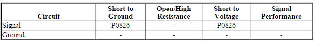
Typical Scan Tool Data
Driver Shift Request
.jpg)
Circuit/System Description
When the shift lever is placed in manual mode (M), the driver shift request , also known as the tap shift function is activated. The driver shift request allows the vehicle operator to shift gears by pushing the plus (+) button for an upshift or minus (-) button for a downshift. The body control module (BCM) supplies a signal circuit to the shift controller. The shift controller has switches connected to a resistor array. When the lever is in the M position, a voltage drop occurs across the resistor network. When the plus or minus button is pushed, a corresponding voltage drop occurs across the resistor network. This voltage drop is monitored by the BCM. The BCM will send the request to the transmission control module (TCM) to perform the upshift or downshift.
The TCM will not allow shifting to the next higher gear if the vehicle speed or engine RPM is too low. The transmission will not allow shifting to the next lower gear if the vehicle speed or engine RPM is too high.
Conditions for Running the DTC
P0815 or P0816
- P0815, P0816, P0826, P1761, P182E, P1876, P1877, or P1915 is not set.
- Engine speed is 400 RPM or greater for 5 s.
- Ignition voltage is 9-32 V.
- Time since the last transmission upshift or downshift is 1 s or greater.
- Runs continuously when above conditions are met.
P0826
- P0826 or P1761 is not set.
- Engine speed is 400-7,500 RPM for 5 s.
- Ignition voltage is 9-32 V.
- Runs continuously when above conditions are met.
Conditions for Setting the DTC
P0815 - Condition 1
TCM detects an upshift request for 1 s with the shift lever in Park or Neutral.
P0815 - Condition 2
TCM detects an upshift request for 10 min with the shift lever in a forward range.
P0816 - Condition 1
TCM detects a downshift request for 1 s with the shift lever in Park or Neutral.
P0816 - Condition 2
TCM detects a downshift request for 10 min with the shift lever in a forward range.
P0826
TCM detects an invalid voltage on the Tap Up/Down signal circuit for 1 min.
Action Taken When the DTC Sets
- P0815, P0816, and P0826 are Type C DTCs.
- TCM inhibits Tap Up/Down function.
Conditions for Clearing the DTC
P0815, P0816, and P0826 are Type C DTCs.
Diagnostic Aids
A high resistance in the signal circuit may not set a DTC. Symptoms could include an inoperative manual mode Tap Up/Down, or a Tap Down shift when the Tap/Up button is pressed.
Reference Information
Schematic Reference
Automatic Transmission Controls Schematics (Encore, MH8 or MHB) , Automatic Transmission Controls Schematics (Encore, MH8 or MHB)
Connector End View Reference
WIRING SYSTEMS AND POWER MANAGEMENT - COMPONENT CONNECTOR END VIEWS - INDEX - ENCORE WIRING SYSTEMS AND POWER MANAGEMENT - COMPONENT CONNECTOR END VIEWS - INDEX - Encore
- Inline Harness Connector End Views (Encore) , Inline Harness Connector End Views (Encore)
Description and Operation
- Electronic Component Description
- Transmission Component and System Description
- Transmission General Description
Electrical Information Reference
- Circuit Testing
- Connector Repairs
- Testing for Intermittent Conditions and Poor Connections
- Wiring Repairs
DTC Type Reference
Powertrain Diagnostic Trouble Code (DTC) Type Definitions (LUV) , Powertrain Diagnostic Trouble Code (DTC) Type Definitions (2H0)
Scan Tool Reference
Control Module References for scan tool information
Circuit/System Verification
WARNING: Refer to Parking Brake and Drive Wheels Warning .
- Ignition ON.
- Verify DTC P182E or P1915 was not set by reviewing the scan tool Freeze Frame/Failure Records.
If DTC P182E or P1915 was set
Refer to DTC P182E or P1915.
If DTC P182E or P1915 was not set
NOTE: The engine may have to be started to move the shift lever out of the Park position. Once out of the Park position, the engine can be turned OFF.
- Ignition ON, engine OFF, S3 Transmission Shift Lever in the M or manual mode position.
- Verify the scan tool Up and Down Shift Switch or TCM Driver Shift Request parameter displays Upshift when pressing the plus (+) switch, Downshift when pressing the minus (-) switch, and None when neither switch is pressed.
If the parameter does not display the correct values
Refer to Circuit/System Testing.
If the parameter displays the correct values
- Operate the vehicle within the Conditions for Running the DTC. You may also operate the vehicle within the conditions that you observed from the Freeze Frame/Failure Records data.
- Verify the DTC does not set.
If the DTC sets
Refer to Circuit/System Testing.
If the DTC does not set
- All OK.
Circuit/System Testing
- Ignition OFF and all vehicle systems OFF, disconnect the harness connector at the S3 Transmission Shift Lever. It may take up to 2 min for all vehicle systems to power down.
- Test for less than 10 ohms between the vehicle harness connector terminal 2 and ground.
If 10 ohms or greater
- Ignition OFF, disconnect the vehicle harness at the ground connection.
- Test for less than 2 ohms in the ground circuit end to end.
- If greater than 2 ohms, repair the open/high resistance in the circuit.
- If less than 2 ohms, repair the ground connection.
If less than 10 ohms
- Ignition ON.
- Test for 11-13 V at the vehicle harness connector between signal circuit terminal 3 and ground.
If not between 11-13 V
- Ignition OFF, disconnect the connector at the BCM.
- Test for infinite resistance between the signal circuit and ground.
- If less than infinite resistance, repair the short to ground in the circuit.
- If infinite resistance
- Test for less than 2 ohms in the signal circuit end to end.
- If 2 ohms or greater, repair the open/high resistance in the circuit.
- If less than 2 ohms, replace the BCM.
If between 11-13 V
- Ignition OFF, connect the harness connector at the S3 Transmission Shift Lever.
- Ignition ON, S3 Transmission Shift Lever in the M or manual mode position.
- Test for voltage between the S3 Transmission Shift Lever connector signal circuit terminal 3 and ground, by back probing the connector, for the conditions listed below.
- 2.0-4.6 V - Plus button pressed
- 5.1-7.3 V - Minus button pressed
- 8.0-10.6 V - Neither button pressed
If voltage values are not correct
Replace the S3 Transmission Shift Lever.
If voltage values are correct
- Replace the K9 Body Control Module.
Repair Instructions
Perform the Diagnostic Repair Verification after completing the diagnostic procedure.
- Refer to Transmission Control Replacement - for Transmission Shift Lever replacement
- Refer to Control Module References - for Body Control Module replacement, programming and setup
DTC P0850-P0852
Diagnostic Instructions
- Perform the Diagnostic System Check - Vehicle prior to using this diagnostic procedure.
- Review Strategy Based Diagnosis for an overview of the diagnostic approach.
- Diagnostic Procedure Instructions provides an overview of each diagnostic category.
DTC Descriptors
DTC P0850
Park/Neutral Position Switch Circuit
DTC P0851
Park/Neutral Position Switch Circuit Low Voltage
DTC P0852
Park/Neutral Position Switch Circuit High Voltage
Diagnostic Fault Information

Typical Scan Tool Data
Park/Neutral Position Switch
.jpg)
Circuit/System Description
The transmission manual shift shaft switch assembly, also known as the transmission internal mode switch is a sliding contact switch attached to the manual shift shaft inside the transmission case. The park/neutral position switch is integrated into the transmission internal mode switch and connects to the transmission control module (TCM) lead-frame through a short wire harness. The park/neutral signal circuit uses the TCM as a pass-through connector only. The TCM provides the low reference circuit to the park/neutral position switch.
The Park/Neutral Signal is sent from the park/neutral switch directly to the Engine Control Module (ECM) and is used for engine start enable.
Conditions for Running the DTC
- Ignition voltage is between 8-18 V.
- Engine speed is 1000 RPM or greater.
- Runs continuously when above conditions are met.
Conditions for Setting the DTC
P0850 and P0851
- ECM detects the Park/Neutral switch signal equals 0 V (Park/Neutral) when the transmission internal mode switch reports a Drive range.
- Throttle position is 10 % or greater.
- Engine torque is 75 (55 lb ft) or greater.
- Vehicle speed is 10 km/h (6 mph) or greater.
- Above conditions must be met for 0.2 s.
P0852
ECM detects the Park/Neutral switch signal equals 12 V (In-Gear) when the IMS reports a Park/Neutral range for 0.2 s.
Action Taken When the DTC Sets
- DTCs P0850, P0851, and P0852 are Type C DTCs.
- ECM uses the transmission internal mode switch position, which is determined by the transmission control module and broadcast over GMLAN, for engine start-up.
Conditions for Clearing the DTC
DTCs P0850, P0851, and P0852 are Type C DTCs.
Reference Information
Schematic Reference
Automatic Transmission Controls Schematics (Encore, MH8 or MHB) , Automatic Transmission Controls Schematics (Encore, MH8 or MHB)
Connector End View Reference
WIRING SYSTEMS AND POWER MANAGEMENT - COMPONENT CONNECTOR END VIEWS - INDEX - ENCORE WIRING SYSTEMS AND POWER MANAGEMENT - COMPONENT CONNECTOR END VIEWS - INDEX - Encore
Inline Harness Connector End Views (Encore) , Inline Harness Connector End Views (Encore)
Description and Operation
- Transmission General Description
- Electronic Component Description
- Transmission Component and System Description
Electrical Information Reference
- Circuit Testing
- Connector Repairs
- Testing for Intermittent Conditions and Poor Connections
- Wiring Repairs
DTC Type Reference
Powertrain Diagnostic Trouble Code (DTC) Type Definitions (LUV) , Powertrain Diagnostic Trouble Code (DTC) Type Definitions (2H0)
Scan Tool Reference
Control Module References for scan tool information
Special Tools
DT-48616-10 Adapter Harness
For equivalent regional tools, refer to Special Tools .
Circuit/System Verification
- Ignition ON.
- Verify that DTC P182E or P1915 is not set.
If any of the DTCs are set
Refer to DTC P182E or P1915.
If none of the DTCs are set
- Verify the range selector lever cable is adjusted properly. Refer to Range Selector Lever Cable Adjustment
- If the cable adjustment is not OK
Adjust, repair or replace as necessary.
- If the cable adjustment is OK
- Ignition ON.
- Verify the scan tool TCM Internal Mode Switch parameter matches the gear shift lever position while slowly moving the gear shift lever from Park through all gear ranges.
If any gear shift lever position does not match
Refer to DTC P182E or P1915.
If all gear positions match
- Verify the scan tool Park/Neutral Position Switch parameter displays Park/Neutral when in Park or Neutral and In-Gear when in Reverse or Drive.
If Park/Neutral or In Gear is not displayed
Refer to Circuit/System Testing.
If Park/Neutral and In Gear is displayed
- Operate the vehicle within the Conditions for Running the DTC. You may also operate the vehicle within the conditions that you observed from the Freeze Frame/Failure Records data.
- Verify the DTC does not set.
If the DTC sets
Refer to Circuit/System Testing.
If the DTC does not set
- All OK
Circuit/System Testing
NOTE: You must perform the Circuit/System Verification first.
- Ignition OFF, disconnect the X1 Q8 Control Solenoid Valve Assembly harness connector at the automatic transmission.
- Install the DT-48616-10 adapter harness to the vehicle harness connector.
NOTE: All testing in steps 3 through 5 will be performed at the DT-48616-10 adapter harness connector.
- Test for less than 5 ohms between the ground circuit terminal 2 and ground.
If 5 ohms or greater
- Ignition OFF.
- Test for less than 2 ohms in the ground circuit end to end.
- If 2 ohms or greater, repair the open/high resistance in the circuit.
- If less than 2 ohms, repair the open/high resistance in the ground connection.
If less than 5 ohms
- Ignition ON.
- Test for 11-13 V between signal circuit terminal 3 and ground.
If not between 11-13 V
- Ignition OFF, remove the harness connector at the K20 Engine Control Module.
- Test for infinite resistance between signal circuit terminal 3 and ground.
- If less than infinite resistance, repair the short to ground in the circuit.
- If infinite resistance.
- Test for less than 2 ohms in the signal circuit end to end.
- If 2 ohms or greater, repair the open/high resistance in the circuit.
- If less than 2 ohms, replace the K20 Engine Control Module.
If between 11-13 V
- Ignition OFF, disconnect the DT-48616-10 adapter harness from the vehicle wire harness.
- Remove the transmission control valve body cover.
- Connect the vehicle harness connector to the Q8 Control Solenoid Valve Assembly.
- Disconnect the B15 Transmission Internal Mode Switch X2 electrical connector from the Q8 Control Solenoid Valve Assembly.
- Ignition ON.
- Verify the scan tool ECM Park/Neutral Position Switch parameter displays In Gear.
If In Gear is not displayed
- Ignition OFF, disconnect the X1 harness connector at the Q8 Control Solenoid Valve Assembly.
- Install the DT-48616-10 adapter harness to the Q8 Control Solenoid Valve Assembly X1 connector.
- Test for infinite resistance between the DT-48616-10 adapter harness connector terminals 2 and 3.
- If less than infinite resistance, replace the Q8 Control Solenoid Valve Assembly.
- If infinite resistance, replace the K20 Engine Control Module.
- If In Gear is displayed
- Connect a 3A fused jumper between the Q8 Control Solenoid Valve Assembly X2 connector signal circuit terminal A and ground. Ignition ON.
- Verify the scan tool ECM Park/Neutral Position Switch parameter displays Park/Neutral.
If Park/Neutral is not displayed
- Ignition OFF, disconnect the X1 harness connector at the Q8 Control Solenoid Valve Assembly.
- Install the DT-48616-10 adapter harness to the Q8 Control Solenoid Valve Assembly X1 connector.
- Test for less than 2 ohms between adapter harness connector terminal 3 and the Q8 Control Solenoid Valve Assembly connector signal circuit terminal A.
- If 2 ohms or greater, replace the Q8 Control Solenoid Valve Assembly.
- If less than 2 ohms, replace the K20 Engine Control Module.
If Park/Neutral is displayed
- Replace the B15 Transmission Internal Mode Switch.
Repair Instructions
Perform the Diagnostic Repair Verification after completing the repair.
- Perform the Transmission Adaptive Values Learn following all transmission repairs.
- Range Selector Lever Cable Adjustment
- Control Valve Body Cover Replacement
- Manual Shift Detent Lever with Shaft Position Switch Assembly Replacement
- Control Valve Body Cover Replacement
- Control Module References - for Engine Control Module or Control Solenoid Valve Assembly replacement, programming and setup
DTC P0961-P0963
Diagnostic Instructions
- Perform the Diagnostic System Check - Vehicle prior to using this diagnostic procedure.
- Review Strategy Based Diagnosis for an overview of the diagnostic approach.
- Diagnostic Procedure Instructions provides an overview of each diagnostic category.
DTC Descriptors
DTC P0961
Line Pressure Control Solenoid Valve Performance
DTC P0962
Line Pressure Control Solenoid Valve Control Circuit Low Voltage
DTC P0963
Line Pressure Control Solenoid Valve Control Circuit High Voltage
Circuit/System Description
The line pressure control solenoid valve is part of the control solenoid valve assembly which has no serviceable components. The normally high line pressure control solenoid valve regulates and directs oil pressure to the pressure regulator valve. Increasing line pressure control solenoid valve pressure increases transmission line pressure. The transmission control module (TCM) varies the current to the line pressure control solenoid valve by controlling the amount of time the low side driver is ON and OFF. Decreasing the ON time, decreases the current to the line pressure control solenoid, which increases line pressure control solenoid oil pressure by closing OFF the solenoid exhaust port. Increasing the current to the line pressure control solenoid decreases line pressure control oil pressure by opening the solenoid exhaust port. Line pressure control solenoid power is supplied by the TCM through a high side driver. The high side driver protects the circuit and components from excessive current flow. If excessive current flow is detected, the high side driver will turn OFF. When the fault is corrected, the high side driver will reset.
Conditions for Running the DTC
- Engine speed is 400-7,500 RPM for 5 s.
- Ignition voltage is 9-32 V.
- Runs continuously when above conditions are met.
Conditions for Setting the DTC
P0961
TCM detects an internal electrical malfunction of the line pressure control solenoid valve circuit where the measured line pressure control solenoid valve current does not equal the commanded line pressure control solenoid valve current for 5 s.
P0962
TCM detects a short to ground on the line pressure control solenoid valve control circuit for 2 s.
P0963
TCM detects an open circuit or short to voltage on the line pressure control solenoid valve control circuit for 5 s.
Action Taken When the DTC Sets
P0961 or P0963
- P0961 and P0963 are Type B DTCs.
- TCM freezes transmission adaptive functions.
- TCM commands maximum line pressure.
P0962
- P0962 is a Type A DTC.
- TCM limits the transmission to 4th gear and reverse.
- TCM inhibits the torque converter clutch (TCC).
- TCM commands maximum line pressure.
- TCM freezes transmission adaptive functions.
- TCM turns the high side driver OFF.
- TCM inhibits neutral idle.
- TCM inhibits Tap Up/Down function.
- TCM inhibits manual shifting of forward gears.
- TCM enables torque management.
Conditions for Clearing the DTC
- P0961 and P0963 are Type B DTCs.
- P0962 is a Type A DTC.
Reference Information
Schematic Reference
Automatic Transmission Controls Schematics (Encore, MH8 or MHB) , Automatic Transmission Controls Schematics (Encore, MH8 or MHB)
Connector End View Reference
WIRING SYSTEMS AND POWER MANAGEMENT - COMPONENT CONNECTOR END VIEWS - INDEX - ENCORE WIRING SYSTEMS AND POWER MANAGEMENT - COMPONENT CONNECTOR END VIEWS - INDEX - Encore
- Inline Harness Connector End Views (Encore) , Inline Harness Connector End Views (Encore)
Description and Operation
- Electronic Component Description
- Transmission Component and System Description
- Transmission General Description
Electrical Information Reference
- Circuit Testing
- Connector Repairs
- Testing for Intermittent Conditions and Poor Connections
- Wiring Repairs
DTC Type Reference
Powertrain Diagnostic Trouble Code (DTC) Type Definitions (LUV) , Powertrain Diagnostic Trouble Code (DTC) Type Definitions (2H0)
Scan Tool Reference
Control Module References for scan tool information
Special Tools
DT-48616-10 Adapter Harness
For equivalent regional tools, refer to Special Tools .
Circuit/System Verification
WARNING: Refer to Parking Brake and Drive Wheels Warning .
- Engine idling, transmission in Park, with service brake applied. Move the S3 Transmission Shift Lever into each gear position for 2-3 s and back into the Park position.
- Verify the scan tool parameters listed below do not display Malfunction:
- Line Pressure Control Solenoid Valve Performance Test Status
- Line Pressure Control Solenoid Valve Control Circuit Low Voltage Test Status
- Line Pressure Control Solenoid Valve Control Circuit High Voltage Test Status
If Malfunction is displayed
Refer to Circuit/System Testing.
If Malfunction is not displayed
- Operate the vehicle within the Conditions for Running the DTC. You may also operate the vehicle within the conditions that you observed from the Freeze Frame/Failure Records.
- Verify the DTC does not set.
If the DTC sets
Refer to Circuit/System Testing.
If the DTC does not set
- All OK.
Circuit/System Testing
NOTE: You must perform the Circuit/System Verification first.
- Ignition OFF, remove the Q8 Control Solenoid Valve Assembly.
- Verify the Q8 Control Solenoid Valve Assembly is not contaminated with any debris and clean as necessary. Refer to Control Solenoid Valve and Transmission Control Module Assembly Inspection.
If contaminated
Repair as necessary.
If not contaminated
- Verify the resistance is within the specified range for each solenoid valve listed in the Control Solenoid Valve and Transmission Control Module Assembly Inspection.
If the resistance is not within range
Replace the Q8 Control Solenoid Valve Assembly.
If the resistance is within range
- Place the Q8 Control Solenoid Valve Assembly on a clean work surface near the transmission assembly.
- Connect the DT-48616-10 adapter harness between the vehicle harness connector and the Q8 Control Solenoid Valve Assembly connector. Ignition ON.
- Verify the scan tool parameters listed below do not display Malfunction:
- Line Pressure Control Solenoid Valve Performance Test Status
- Line Pressure Control Solenoid Valve Control Circuit Low Voltage Test Status
- Line Pressure Control Solenoid Valve Control Circuit High Voltage Test Status
If Malfunction is displayed
Replace the Q8 Control Solenoid Valve Assembly.
If Malfunction is not displayed
- All OK.
Repair Instructions
Perform the Diagnostic Repair Verification after completing the repair.
- Perform the Transmission Adaptive Values Learn following all transmission repairs
- Control Module References - for Control Solenoid Valve Assembly replacement, programming and setup
DTC P0965-P0967
Diagnostic Instructions
- Perform the Diagnostic System Check - Vehicle prior to using this diagnostic procedure.
- Review Strategy Based Diagnosis for an overview of the diagnostic approach.
- Diagnostic Procedure Instructions provides an overview of each diagnostic category.
DTC Descriptors
DTC P0965
Pressure Control Solenoid Valve 2 Performance
DTC P0966
Pressure Control Solenoid Valve 2 Control Circuit Low Voltage
DTC P0967
Pressure Control Solenoid Valve 2 Control Circuit High Voltage
Circuit/System Description
Pressure control solenoid valve 2 is part of the control solenoid valve assembly which has no serviceable components. The normally low pressure control solenoid valve 2 regulates and directs fluid pressure to the 3-5 reverse clutch regulator valve. Increasing pressure control solenoid valve 2 pressure increases pressure to the 3- 5 reverse clutch. The transmission control module (TCM) varies the current to the pressure control solenoid valve 2 by controlling the amount of time the low side driver is ON and OFF. Increasing the current to the pressure control solenoid valve 2 increases pressure control solenoid valve 2 fluid pressure by closing OFF the solenoid valve exhaust port. Decreasing the current to the pressure control solenoid valve 2 decreases clutch pressure control solenoid valve 2 fluid pressure by opening the solenoid valve exhaust port. Power to pressure control solenoid valve 2 is supplied by the TCM through a high side driver. The high side driver protects the circuit and components from excessive current flow. If excessive current flow is detected, the high side driver will turn OFF. When the fault is corrected, the high side driver will reset.
Conditions for Running the DTC
- Engine speed is 400-7,500 RPM for 5 s.
- Ignition voltage is 9-32 V.
- Runs continuously when above conditions are met.
Conditions for Setting the DTC
P0965
TCM detects an internal electrical performance malfunction of the pressure control solenoid valve 2 control circuit where the measured pressure control solenoid valve 2 current does not equal the commanded pressure control solenoid valve 2 current for 5 s.
P0966
TCM detects a short to ground on the pressure control solenoid valve 2 control circuit for 1 s.
P0967
TCM detects an open or short to voltage on the pressure control solenoid valve 2 control circuit for 1 s.
Action Taken When the DTC Sets
P0965
- P0965 is a Type C DTC.
- TCM freezes transmission adaptive functions on the 3-5 Reverse clutch.
P0966 or P0967
- P0966 and P0967 are Type A DTCs.
- TCM limits the transmission to 4th gear and reverse.
- TCM commands maximum line pressure.
- TCM freezes transmission adaptive functions.
- TCM forces the torque converter clutch (TCC) OFF.
- TCM forces the high side driver OFF.
- TCM inhibits Tap Up/Down function.
- TCM inhibits manual shifting of forward gears.
- TCM enables torque management.
Conditions for Clearing the DTC
- P0965 is a Type C DTC.
- P0966 and P0967 are Type A DTCs.
Reference Information
Schematic Reference
Automatic Transmission Controls Schematics (Encore, MH8 or MHB) , Automatic Transmission Controls Schematics (Encore, MH8 or MHB)
Connector End View Reference
WIRING SYSTEMS AND POWER MANAGEMENT - COMPONENT CONNECTOR END VIEWS - INDEX - ENCORE WIRING SYSTEMS AND POWER MANAGEMENT - COMPONENT CONNECTOR END VIEWS - INDEX - Encore
- Inline Harness Connector End Views (Encore) , Inline Harness Connector End Views (Encore)
Description and Operation
- Electronic Component Description
- Transmission Component and System Description
- Transmission General Description
Electrical Information Reference
- Circuit Testing
- Connector Repairs
- Testing for Intermittent Conditions and Poor Connections
- Wiring Repairs
DTC Type Reference
Powertrain Diagnostic Trouble Code (DTC) Type Definitions (LUV) , Powertrain Diagnostic Trouble Code (DTC) Type Definitions (2H0)
Scan Tool Reference
Control Module References for scan tool information
Special Tools
DT-48616-10 Adapter Harness
For equivalent regional tools, refer to Special Tools .
Circuit/System Verification
- Operate the vehicle in second gear long enough to ensure at least a 3ºC (5ºF) rise in TCM temperature, then operate the vehicle with the transmission in Park for 5 s.
- Operate the vehicle in drive range. Allow the transmission to shift through all forward gear ranges.
- Verify the scan tool parameters listed below do not display Malfunction:
- Pressure Control Solenoid Valve 2 Performance Test Status
- Pressure Control Solenoid Valve 2 Control Circuit Low Voltage Test Status
- Pressure Control Solenoid Valve 2 Control Circuit High Voltage Test Status
If Malfunction is displayed
Refer to Circuit/System Testing.
If Malfunction is not displayed
- Operate the vehicle within the Conditions for Running the DTC. You may also operate the vehicle within the conditions that you observed from the Freeze Frame/Failure Records data.
- Verify the DTC does not set.
If the DTC sets
Refer to Circuit/System Testing.
If the DTC does not set
- All OK.
Circuit/System Testing
NOTE: You must perform the Circuit/System Verification first.
- Ignition OFF, remove the Q8 Control Solenoid Valve Assembly.
- Verify the Q8 Control Solenoid Valve Assembly is not contaminated with any debris and clean as necessary. Refer to Control Solenoid Valve and Transmission Control Module Assembly Inspection.
- If contaminated
Repair as necessary.
- If not contaminated
- Verify the resistance is within the specified range for each solenoid valve listed in the Control Solenoid Valve and Transmission Control Module Assembly Inspection.
If the resistance is not within range
Replace the Q8 Control Solenoid Valve Assembly.
If the resistance is within range
- Place the Q8 Control Solenoid Valve Assembly on a clean work surface near the transmission assembly.
- Connect the DT-48616-10 adapter harness between the vehicle harness connector and the Q8 Control Solenoid Valve Assembly connector. Ignition ON.
- Verify the scan tool parameters listed below do not display Malfunction:
- Pressure Control Solenoid Valve 2 Performance Test Status
- Pressure Control Solenoid Valve 2 Control Circuit Low Voltage Test Status
- Pressure Control Solenoid Valve 2 Control Circuit High Voltage Test Status
If Malfunction is displayed
Replace the Q8 Control Solenoid Valve Assembly.
If Malfunction is not displayed
- All OK.
Repair Instructions
Perform the Diagnostic Repair Verification after completing the repair.
- Perform the Transmission Adaptive Values Learn following all transmission repairs
- Control Module References for Control Solenoid Valve Assembly replacement, programming and setup
DTC P0969-P0971
Diagnostic Instructions
- Perform the Diagnostic System Check - Vehicle prior to using this diagnostic procedure.
- Review Strategy Based Diagnosis for an overview of the diagnostic approach.
- Diagnostic Procedure Instructions provides an overview of each diagnostic category.
DTC Descriptors
DTC P0969
Pressure Control Solenoid Valve 3 Performance
DTC P0970
Pressure Control Solenoid Valve 3 Control Circuit Low Voltage
DTC P0971
Pressure Control Solenoid Valve 3 Control Circuit High Voltage
Circuit/System Description
Pressure control solenoid valve 3 is part of the control solenoid valve assembly which has no serviceable components. The normally high pressure control solenoid valve 3 regulates and directs fluid pressure to the R1/4-5-6 regulator valve. Increasing pressure control solenoid valve 3 pressure increases pressure to the low and reverse clutch or 4-5-6 clutch, depending on the position of the clutch select valve. The transmission control module (TCM) varies current to pressure control Solenoid valve 3 by controlling the time the low side driver is ON and OFF. Decreasing the current to pressure control solenoid valve 3 increases fluid pressure by closing off the solenoid valve exhaust port. Increasing the current to the pressure control solenoid valve 3 decreases fluid pressure by opening the exhaust port. Power is supplied to the pressure control solenoid valve 3 by the TCM through a high side driver. The high side driver protects the circuit and components from excessive current flow. If excessive current flow is detected, the high side driver will turn OFF. When the fault is corrected, the high side driver will reset.
Conditions for Running the DTC
- Engine speed is 400-7,500 RPM for 5 s.
- Ignition voltage is 9-32 V.
- Runs continuously when above conditions are met.
Conditions for Setting the DTC
P0969
TCM detects an internal electrical performance malfunction of the pressure control solenoid valve 3 control circuit where the measured pressure control solenoid valve 3 currents does not equal the commanded clutch pressure control solenoid valve 3 current for 5 s.
P0970
TCM detects a short to ground on the pressure control solenoid valve 3 control circuit for 1 s.
P0971
TCM detects an open or short to voltage on the pressure control solenoid valve 3 control circuit for 1 s.
Action Taken When the DTC Sets
P0969
- P0969 is a Type C DTC.
- TCM freezes transmission adaptive functions on the low and reverse clutch and the 4-5-6 clutch.
P0970 or P0971
- P0970 and P0971 are Type A DTCs.
- TCM limits the transmission to 4th gear and reverse.
- TCM commands maximum line pressure.
- TCM freezes transmission adaptive functions.
- TCM enables torque management.
- TCM inhibits Tap Up/Down function.
- TCM inhibits manual shifting of forward gears.
- TCM inhibits auto grade braking.
- TCM forces the high side driver OFF - P0970 only.
- TCM forces the torque converter clutch (TCC) OFF - P0970 only.
Conditions for Clearing the DTC
- P0969 is a Type C DTC.
- P0970 and P0971 are Type A DTCs.
Reference Information
Schematic Reference
Automatic Transmission Controls Schematics (Encore, MH8 or MHB) , Automatic Transmission Controls Schematics (Encore, MH8 or MHB)
Connector End View Reference
WIRING SYSTEMS AND POWER MANAGEMENT - COMPONENT CONNECTOR END VIEWS - INDEX - ENCORE WIRING SYSTEMS AND POWER MANAGEMENT - COMPONENT CONNECTOR END VIEWS - INDEX - Encore
- Inline Harness Connector End Views (Encore) , Inline Harness Connector End Views (Encore)
Description and Operation
- Electronic Component Description
- Transmission Component and System Description
- Transmission General Description
Electrical Information Reference
- Circuit Testing
- Connector Repairs
- Testing for Intermittent Conditions and Poor Connections
- Wiring Repairs
DTC Type Reference
Powertrain Diagnostic Trouble Code (DTC) Type Definitions (LUV) , Powertrain Diagnostic Trouble Code (DTC) Type Definitions (2H0)
Scan Tool Reference
Control Module References for scan tool information
Special Tools
DT-48616-10 Adapter Harness
For equivalent regional tools, refer to Special Tools .
Circuit/System Verification
- Operate the vehicle in second gear long enough to ensure at least a 3ºC (5ºF) rise in TCM temperature, then operate the vehicle with the transmission in Park for 5 s.
- Operate the vehicle in drive range. Allow the transmission to shift through all forward gear ranges.
- Verify the scan tool parameters listed below do not display Malfunction:
- Pressure Control Solenoid Valve 3 Performance Test Status
- Pressure Control Solenoid Valve 3 Control Circuit Low Voltage Test Status
- Pressure Control Solenoid Valve 3 Control Circuit High Voltage Test Status
If Malfunction is displayed
Refer to Circuit/System Testing
If Malfunction is not displayed
- Operate the vehicle within the Conditions for Running the DTC. You may also operate the vehicle within the conditions that you observed from the Freeze Frame/Failure Records data.
- Verify the DTC does not set.
If the DTC sets
Refer to Circuit/System Testing.
If the DTC does not set
- All OK.
Circuit/System Testing
NOTE: You must perform the Circuit/System Verification first.
- Ignition OFF, remove the Q8 Control Solenoid Valve Assembly.
- Verify the Q8 Control Solenoid Valve Assembly is not contaminated with any debris and clean as necessary. Refer to Control Solenoid Valve and Transmission Control Module Assembly Inspection.
If contaminated
Repair as necessary.
If not contaminated
- Verify the resistance is within the specified range for each solenoid valve listed in the Control Solenoid Valve and Transmission Control Module Assembly Inspection.
If the resistance is not within range
Replace the Q8 Control Solenoid Valve Assembly.
If the resistance is within range
- Place the Q8 Control Solenoid Valve Assembly on a clean work surface near the transmission assembly.
- Connect the DT-48616-10 adapter harness between the vehicle harness connector and the Q8 Control Solenoid Valve Assembly connector. Ignition ON.
- Verify the scan tool parameters listed below do not display Malfunction:
- Pressure Control Solenoid Valve 2 Performance Test Status
- Pressure Control Solenoid Valve 2 Control Circuit Low Voltage Test Status
- Pressure Control Solenoid Valve 2 Control Circuit High Voltage Test Status
If Malfunction is displayed
Replace the Q8 Control Solenoid Valve Assembly.
If Malfunction is not displayed
- All OK.
Repair Instructions
Perform the Diagnostic Repair Verification after completing the repair.
- Perform the Transmission Adaptive Values Learn following all transmission repairs
- Control Module References - for Control Solenoid Valve Assembly replacement, programming and setup
DTC P0973 OR P0974
Diagnostic Instructions
- Perform the Diagnostic System Check - Vehicle prior to using this diagnostic procedure.
- Review Strategy Based Diagnosis for an overview of the diagnostic approach.
- Diagnostic Procedure Instructions provides an overview of each diagnostic category.
DTC Descriptors
DTC P0973
Shift Solenoid Valve 1 Control Circuit Low Voltage
DTC P0974
Shift Solenoid Valve 1 Control Circuit High Voltage
Circuit/System Description
The shift solenoid valve 1 is part of the control solenoid valve assembly which has no serviceable components.
Shift solenoid valve 1 is a normally closed ON/OFF solenoid and is controlled by the transmission control module (TCM) through a low side driver. When the shift solenoid valve 1 is energized (ON), fluid pressure is directed to the clutch select valve. Power to shift solenoid valve 1 is supplied by the TCM through a high side driver. The high side driver protects the circuit and components from excessive current flow. If excessive current flow is detected, the high side driver will turn OFF. When the fault is corrected, the high side driver will reset.
Conditions for Running the DTC
- Engine speed is 400-7500 RPM for 5 s.
- Ignition voltage is 9-32 V.
Conditions for Setting the DTC
P0973
TCM detects a short to ground on the shift solenoid valve 1 control circuit for 2 s.
P0974
TCM detects an open or short to voltage on the shift solenoid valve 1 control circuit for 2 s.
Action Taken When the DTC Sets
P0973
- DTC P0973 is a Type A DTC.
- TCM freezes transmission adaptive functions.
- TCM commands maximum line pressure.
- TCM limits the transmission to neutral or 2nd gear and reverse.
- TCM inhibits neutral idle.
- TCM inhibits auto grade braking.
- TCM inhibits the Tap Up/Tap Down function.
- TCM inhibits manual shifting of forward gears.
P0974
- DTC P0974 is a Type B DTC.
- TCM inhibits 1st gear.
- TCM inhibits neutral idle.
Conditions for Clearing the DIC/DTC
- DTC P0973 is a Type A DTC.
- DTC P0974 is a Type B DTC.
Reference Information
Schematic Reference
Automatic Transmission Controls Schematics (Encore, MH8 or MHB) , Automatic Transmission Controls Schematics (Encore, MH8 or MHB)
Connector End View Reference
WIRING SYSTEMS AND POWER MANAGEMENT - COMPONENT CONNECTOR END VIEWS - INDEX - ENCORE WIRING SYSTEMS AND POWER MANAGEMENT - COMPONENT CONNECTOR END VIEWS - INDEX - Encore
- Inline Harness Connector End Views (Encore) , Inline Harness Connector End Views (Encore)
Description and Operation
- Electronic Component Description
- Transmission Component and System Description
- Transmission General Description
Electrical Information Reference
- Circuit Testing
- Connector Repairs
- Testing for Intermittent Conditions and Poor Connections
- Wiring Repairs
DTC Type Reference
Powertrain Diagnostic Trouble Code (DTC) Type Definitions (LUV) , Powertrain Diagnostic Trouble Code (DTC) Type Definitions (2H0)
Scan Tool Reference
Control Module References for scan tool information
Special Tools
DT-48616-10 Adapter Harness
For equivalent regional tools, refer to Special Tools
Circuit/System Verification
- Operate the vehicle in 2nd gear long enough to ensure at least a 3ºC (5ºF) rise in TCM temperature.
- Place the gear selector in Reverse for 5 s and then idle vehicle for 5 s.
- Verify the scan tool parameters listed below do not display Malfunction:
- Shift Solenoid Valve 1 Control Circuit Low Voltage Test Status
- Shift Solenoid Valve 1 Control Circuit Open Test Status
- Shift Solenoid Valve 1 Control Circuit High Voltage Test Status
If Malfunction is displayed
Refer to Circuit/System Testing.
If Malfunction is not displayed
- Operate the vehicle within the Conditions for Running the DTC. You may also operate the vehicle within the conditions that you observed from the Freeze Frame/Failure Records data.
- Verify the DTC does not set.
If the DTC sets
Refer to Circuit/System Testing.
If the DTC does not set
- All OK.
Circuit/System Testing
NOTE: You must perform the Circuit/System Verification first.
- Ignition OFF, remove the Q8 Control Solenoid Valve Assembly.
- Verify the Q8 Control Solenoid Valve Assembly is not contaminated with any debris and clean as necessary. Refer to Control Solenoid Valve and Transmission Control Module Assembly Inspection.
If contaminated
Repair as necessary.
If not contaminated
- Verify the resistance is within the specified range for each solenoid valve listed in the Control Solenoid Valve and Transmission Control Module Assembly Inspection.
If the resistance is not within range
Replace the Q8 Control Solenoid Valve Assembly
If the resistance is within range
- Place the Q8 Control Solenoid Valve Assembly on a clean work surface near the transmission assembly.
- Connect the DT-48616-10 adapter harness between the vehicle harness connector and the Q8 Control Solenoid Valve Assembly connector. Ignition ON.
- Verify the scan tool parameters listed below do not display Malfunction:
- Shift Solenoid Valve 1 Control Circuit Low Voltage Test
- Shift Solenoid Valve 1 Control Circuit Open Test
- Shift Solenoid Valve 1 Control Circuit High Voltage Test
If Malfunction is displayed
Replace the Q8 Control Solenoid Valve Assembly.
If Malfunction is not displayed
- All OK.
Repair Instructions
Perform the Diagnostic Repair Verification after completing the repair.
- Perform the Transmission Adaptive Values Learn following all transmission repairs
- Control Module References - for Control Solenoid Valve Assembly replacement, programming and setup
DTC P1761
Diagnostic Instructions
- Perform the Diagnostic System Check - Vehicle prior to using this diagnostic procedure.
- Review Strategy Based Diagnosis for an overview of the diagnostic approach.
- Diagnostic Procedure Instructions provides an overview of each diagnostic category.
DTC Descriptor
DTC P1761
Up and Down Shift Switch Signal Message Counter Incorrect
Circuit/System Description
When the shift lever is placed in the M position, the transmission will enter manual mode, also known as tap shift. The manual mode allows the vehicle operator to select an upshift by pressing the plus (+) button or downshift by pressing the minus (-) button. The body control module (BCM) supplies a signal circuit to the shift controller. The shift controller has switches connected to a resistor array. A voltage drop occurs across the resistor network. When the plus or minus button is pushed, a corresponding voltage drop occurs across the resistor network. This voltage drop is monitored by the BCM. The BCM will send the request to the transmission control module (TCM) for an upshift or downshift. The BCM internal counter increments each time the tap shift signal status is sent and the BCM sends the rolling count with the tap shift signal status. The TCM counter increments each time the tap shift signal status is received. The DTC will set if the rolling count value of the TCM does not match the rolling count sent from the BCM.
Conditions for Running the DTC
- Engine speed is 400-7,500 RPM for 5 s.
- Runs continuously when above condition is met.
Conditions for Setting the DTC
TCM detects the internal rolling count value does not match the expected BCM count, 3 times within 10 s.
Action Taken When the DTC Sets
- P1761 is a Type C DTC.
- TCM inhibits the Tap Up Tap Down function.
- TCM inhibits manual shifting of forward gears.
Conditions for Clearing the DTC
P1761 is a Type C DTC.
Reference Information
Schematic Reference
- Automatic Transmission Controls Schematics (Encore, MH8 or MHB) , Automatic Transmission Controls Schematics (Encore, MH8 or MHB)
- Body Control System Schematics (Encore) , Body Control System Schematics (Encore)
- Data Communication Schematics (Encore) , Data Communication Schematics (Encore)
Connector End View Reference
WIRING SYSTEMS AND POWER MANAGEMENT - COMPONENT CONNECTOR END VIEWS - INDEX - ENCORE WIRING SYSTEMS AND POWER MANAGEMENT - COMPONENT CONNECTOR END VIEWS - INDEX - Encore
- Inline Harness Connector End Views (Encore) , Inline Harness Connector End Views (Encore)
Description and Operation
- Electronic Component Description
- Transmission Component and System Description
- Transmission General Description
Electrical Information Reference
- Circuit Testing
- Connector Repairs
- Testing for Intermittent Conditions and Poor Connections
- Wiring Repairs
DTC Type Reference
Powertrain Diagnostic Trouble Code (DTC) Type Definitions (LUV) , Powertrain Diagnostic Trouble Code (DTC) Type Definitions (2H0)
Scan Tool Reference
Control Module References for scan tool information
Circuit/System Verification
NOTE:
- DTC P1761 is an informational DTC.
- Diagnose all other body control module DTCs prior to DTC P1761.
- Verify there are no other body control module or communication DTCs set.
If a DTC is set
Refer to Diagnostic Trouble Code (DTC) List - Vehicle .
If a DTC is not set
- Complete the diagnosis by looking for a GMLAN circuit fault. Refer to Scan Tool Does Not Communicate with High Speed GMLAN Device .
If a GMLAN circuit fault is found
Repair as necessary.
If a GMLAN circuit fault is not found
- All OK.
Repair Instructions
Perform the Diagnostic Repair Verification after completing the repair.
- Perform the Transmission Adaptive Values Learn following all transmission repairs
- Control Module References - for Body Control Module and Control Solenoid Valve Assembly replacement, programming and setup
DTC P182E OR P1915
Diagnostic Instructions
- Perform the Diagnostic System Check - Vehicle prior to using this diagnostic procedure.
- Review Strategy Based Diagnosis for an overview of the diagnostic approach.
- Diagnostic Procedure Instructions provides an overview of each diagnostic category.
DTC Descriptors
DTC P182E
Internal Mode Switch Indicates Invalid Range
DTC P1915
Internal Mode Switch Does Not Indicate Park/Neutral During Start
Diagnostic Fault Information
.jpg)
Typical Scan Tool Data
Internal Mode Switch A/B/C/P

Circuit/System Description
The manual shift detent lever with shaft position switch assembly, also known as the transmission internal mode switch assembly, is a sliding contact switch attached to the manual shift detent lever shaft inside the transmission. The 4 inputs to the transmission control module (TCM) from the switch indicate the position selected by the transmission manual shaft. The input voltage at the TCM is high when the switch is open and low when the switch is closed to ground. The state of each input is displayed on the scan tool TCM Internal Mode Switch A/B/C/P parameter. The Internal Mode Switch A/B/C/P parameter represents transmission range Signal A, Signal B, Signal C, and Signal P.
The park/neutral position switch is integrated into the transmission internal mode switch. The circuit uses the TCM as a pass-through connector only.
The park/neutral signal is sent from the park/neutral switch directly to the engine control module (ECM) and is used for engine start enable.
Conditions for Running the DTC
P182E
- DTC P0101, P0102, P0103, P0106, P0107, P0108, P0171, P0172, P0174, P0175, P0201, P0202, P0203, P0204, P0205, P0206, P0207, P0208, P0300, P0301, P0302, P0303, P0304, P0305, P0306, P0307, P0308, P0401, P042E, P0722, or P0723 is not set.
- Engine speed is 400-7,500 RPM for 5 s.
- Ignition voltage is 9-32 V.
- Engine torque signal is valid.
- DTC runs continuously when the above conditions are met.
P1915
- DTC P0722, P0723, or P1915 is not set.
- Transmission output shaft speed is 90 RPM or less.
- Ignition voltage is 6-32 V.
- DTC runs when conditions above are met during engine start sequence.
Conditions for Setting the DTC
P182E
Internal mode switch does not indicate a valid Park, Reverse, Neutral, or Drive Range position for 7 s.
P1915
Internal mode switch does not indicate Park or Neutral during the following sequence:
- Engine speed is less than 50 RPM for greater than 0.10 s.
- Engine speed is 50-480 RPM for greater than 0.07 s.
- Engine speed is greater than 500 RPM and the transmission input speed is greater than 100 RPM for greater than 1.25 s.
Action Taken When the DTC Sets
- P182E and P1915 are Type A DTCs.
- TCM commands maximum line pressure.
- TCM turns OFF all solenoids.
- TCM freezes transmission adaptive functions.
- TCM limits the transmission to reverse and 4th gear.
- TCM forces the torque converter clutch (TCC) OFF.
- TCM inhibits the Tap Up/Tap Down function.
- TCM inhibits neutral idle.
- TCM inhibits auto grade braking.
- TCM inhibits manual shifting of forward gears.
- TCM turns the high side driver OFF.
- TCM enables torque management.
Conditions for Clearing the DTC
P182E and P1915 are Type A DTCs.
Reference Information
Schematic Reference
Automatic Transmission Controls Schematics (Encore, MH8 or MHB) , Automatic Transmission Controls Schematics (Encore, MH8 or MHB)
Connector End View Reference
WIRING SYSTEMS AND POWER MANAGEMENT - COMPONENT CONNECTOR END VIEWS - INDEX - ENCORE WIRING SYSTEMS AND POWER MANAGEMENT - COMPONENT CONNECTOR END VIEWS - INDEX - Encore
- Inline Harness Connector End Views (Encore) , Inline Harness Connector End Views (Encore)
Description and Operation
- Electronic Component Description
- Transmission Component and System Description
- Transmission General Description
Electrical Information Reference
- Circuit Testing
- Connector Repairs
- Testing for Intermittent Conditions and Poor Connections
- Wiring Repairs
DTC Type Reference
Powertrain Diagnostic Trouble Code (DTC) Type Definitions (LUV) , Powertrain Diagnostic Trouble Code (DTC) Type Definitions (2H0)
Scan Tool Reference
Control Module References for scan tool information
Special Tools
DT-48616-10 Adapter Harness
For equivalent regional tools, refer to Special Tools .
Circuit/System Verification
- Verify the range selector lever cable is adjusted properly. Refer to Range Selector Lever Cable Adjustment .
- If cable adjustment is not OK
Repair as necessary.
If cable adjustment is OK
- Ignition ON.
- Verify the scan tool TCM Internal Mode Switch A/B/C/P parameter matches the Transmission Internal Mode Switch Logic table for each transmission shift lever position.
If the parameter does not match
Refer to Circuit/System Testing.
If the parameter matches
- Verify the scan tool engine control module Park/Neutral Position Switch parameter displays Park/Neutral with the gear shift lever in Park or Neutral and In Gear in Reverse or Drive.
If Park/Neutral or In Gear is not displayed
Refer to Circuit/System Testing.
If Park/Neutral and In Gear is displayed
- Operate the vehicle within the Conditions for Running the DTC. You may also operate the vehicle within the conditions that you observed from the Freeze Frame/Failure Records data.
- Verify the DTC does not set.
If the DTC sets
Refer to Circuit/System Testing.
If the DTC does not set
- All OK.
Circuit/System Testing
NOTE: You must perform Circuit/System Verification first.
- Ignition OFF, remove the control valve body cover.
- Connect the vehicle harness connector to the Q8 Control Solenoid Valve Assembly.
- Disconnect the B15 Transmission Internal Mode Switch connector at the Q8 Control Solenoid Valve Assembly.
- Ignition ON.
- Verify the scan tool engine control module Park/Neutral Position Switch parameter displays In Gear.
If In Gear is not displayed
- Ignition OFF, disconnect the vehicle harness X1 connector at the Q8 Control Solenoid Valve Assembly.
- Install the DT-48616-10 adapter harness to the X1 connector at the Q8 Control Solenoid Valve Assembly.
- Test for infinite resistance between the DT-48616-10 adapter harness connector terminals 2 and 3.
- If less than infinite resistance, replace the Q8 Control Solenoid Valve Assembly.
- If infinite resistance.
- Disconnect the harness connector at the K20 Engine Control Module.
- Test for infinite resistance between the signal circuit and ground at the vehicle harness K20 Engine Control Module connector.
- If less than infinite resistance, repair the short to ground on the circuit.
- If infinite resistance, replace the K20 Engine Control Module.
If In Gear is displayed
- Verify the scan tool transmission control module Internal Mode Switch A/B/C/P parameter displays High High High High.
If High High High High is not displayed
Replace the Q8 Control Solenoid Valve Assembly.
If High High High High is displayed
- Install a 3 A fused jumper wire between the low reference circuit terminal F and each signal circuit listed below one at a time at the Q8 Control Solenoid Valve Assembly.
- Signal A - terminal B
- Signal B - terminal C
- Signal C - terminal D
- Signal P - terminal E
- Verify the scan tool transmission control module A/B/C/P parameter displays 1 Low and 3 High when a signal circuit is grounded.
If 1 Low and 3 High is not displayed
Replace the Q8 Control Solenoid Valve Assembly.
If 1 Low and 3 High is displayed
- Connect a 3-amp fused jumper wire between terminal A and terminal F.
- Verify the ECM Park/Neutral Position Switch parameter displays Park/Neutral.
If Park/Neutral is not displayed
- Ignition OFF, remove the jumper wire and disconnect the X1 connector at the Q8 Control Solenoid Valve Assembly.
- Install the DT-48616-10 adapter harness to the X1 connector at the Q8 Control Solenoid Valve Assembly.
- Test for less than 2 ohms between the adapter harness terminal 2 and the X2 connector terminal F at the Q8 Control Solenoid Valve Assembly.
- If greater than 2 ohms, replace the Q8 Control Solenoid Valve Assembly.
- If less than 2 ohms .
- Disconnect the connector at the K20 Engine Control Module.
- Test for less than 2 ohms in the vehicle harness park/neutral signal circuit, end to end.
- If 2 ohms or greater, repair the open/high resistance in the circuit.
- If less than 2 ohms, replace the K20 Engine Control Module.
- If Park/Neutral is displayed
- Replace the B15 Transmission Internal Mode Switch.
Repair Instructions
Perform the Diagnostic Repair Verification after completing the repair.
- Perform the Transmission Adaptive Values Learn following all transmission repairs.
- Control Valve Body Cover Replacement
- Manual Shift Detent Lever with Shaft Position Switch Assembly Replacement
- Range Selector Lever Cable Adjustment
- Control Module References - for Control Solenoid Valve Assembly or Engine Control Module replacement, programming and setup
DTC P1876
Diagnostic Instructions
- Perform the Diagnostic System Check - Vehicle prior to using this diagnostic procedure.
- Review Strategy Based Diagnosis for an overview of the diagnostic approach.
- Diagnostic Procedure Instructions provides an overview of each diagnostic category.
DTC Descriptor
DTC P1876
Up and Down Shift Enable Switch Circuit Low Voltage
Circuit/System Description
When the shift lever is placed in manual mode (M), the driver shift request , also known as the tap shift function, is activated. The driver shift request allows the vehicle operator to shift gears by pushing the plus (+) button for an upshift or minus (-) button for a downshift. The body control module (BCM) supplies a signal circuit to the shift controller. The shift controller has switches connected to a resistor array. When the lever is in the M position, a voltage drop occurs across the resistor network. When the plus or minus button is pushed, a corresponding voltage drop occurs across the resistor network. This voltage drop is monitored by the BCM. The BCM will send the request to the transmission control module (TCM) to perform the upshift or downshift. The TCM will not allow shifting to the next higher gear if the vehicle speed or engine RPM is too low. The transmission will not allow shifting to the next lower gear if the vehicle speed or engine RPM is too high.
Conditions for Running the DTC
- DTC P0815, P0816, P0826, P1761, P1825, P1876, P1877, P1915, or U0100 is not set.
- Engine speed is 400-7,500 RPM for 5 s.
- Ignition voltage is 9-32 V.
- Runs continuously when above conditions are met.
Conditions for Setting the DTC
Transmission control module (TCM) detects a Tap Enable Switch request for 3 s when the shift lever is in Park, Reverse, or Neutral, a total of 5 times.
Action Taken When the DTC Sets
- P1876 is a Type C DTC.
- TCM inhibits Tap-Up/Tap-Down functions.
- TCM inhibits manual up, manual down shifts with the shift selector.
Conditions for Clearing the DTC
P1876 is a Type C DTC
Reference Information
Schematic Reference
Automatic Transmission Controls Schematics (Encore, MH8 or MHB) , Automatic Transmission Controls Schematics (Encore, MH8 or MHB)
Connector End View Reference
WIRING SYSTEMS AND POWER MANAGEMENT - COMPONENT CONNECTOR END VIEWS - INDEX - ENCORE WIRING SYSTEMS AND POWER MANAGEMENT - COMPONENT CONNECTOR END VIEWS - INDEX - Encore
- Inline Harness Connector End Views (Encore) , Inline Harness Connector End Views (Encore)
Description and Operation
- Electronic Component Description
- Transmission Component and System Description
- Transmission General Description
Electrical Information Reference
- Circuit Testing
- Connector Repairs
- Testing for Intermittent Conditions and Poor Connections
- Wiring Repairs
DTC Type Reference
Powertrain Diagnostic Trouble Code (DTC) Type Definitions (LUV) , Powertrain Diagnostic Trouble Code (DTC) Type Definitions (2H0)
Scan Tool Reference
Control Module References for scan tool information
Circuit/System Verification
WARNING: Refer to Parking Brake and Drive Wheels Warning .
- Verify DTC P182E or P1915 was not set by reviewing the scan tool Freeze Frame/Failure Records.
If DTC P182E or P1915 was set
Refer to DTC P182E or P1915.
If DTC P182E or P1915 was not set
- Ignition ON.
NOTE: The engine may have to be started to move the shift lever out of the Park position. Once out of the Park position, the engine can be turned OFF.
- Verify the gear shift lever position matches the scan tool TCM Internal Mode Switch parameter while slowly moving the gear shift lever from Park through all ranges.
If the specified values are not correct
Refer to Range Selector Lever Cable Adjustment .
If the specified values are correct
- Shift lever in the M position.
- Verify the scan tool Driver Shift Request parameter changes from Inactive to Upshift when the plus button is pressed, and from Inactive to Downshift when the minus button is pressed.
If the Driver Shift Request parameter does not display the correct values
Refer to Circuit/System Testing
If the Driver Shift Request parameter displays the correct values
- Operate the vehicle within the Conditions for Running the DTC. You may also operate the vehicle within the conditions that you observed from the Freeze Frame/Failure Records data.
- Verify the DTC does not set.
If the DTC sets
Refer to Circuit/System Testing.
If the DTC does not set
- All OK.
NOTE: You must perform Circuit/System Verification first.
- Ignition OFF, disconnect the harness connector at the S3 Transmission Shift Lever.
- Test for less than 10 ohms between the vehicle harness connector terminal 2 and ground.
If 10 ohms or greater
- Ignition OFF, disconnect the vehicle harness at the ground connection.
- Test for less than 2 ohms in the ground circuit end to end
- If 2 ohms or greater, repair the open/high resistance in the circuit
- If less than 2 ohms, repair the open/high resistance in the ground connection.
If less than 10 ohms
- Ignition ON.
- Test for 11-13 V at the vehicle harness connector between signal circuit terminal 3 and ground.
If not between 11-13 V
- Ignition OFF, disconnect the connector at the BCM.
- Test for infinite resistance between the signal circuit and ground.
- If less than infinite resistance, repair the short to ground in the circuit.
- If infinite resistance.
- Test for less than 2 ohms in the signal circuit end to end.
- If 2 ohms or greater, repair the open/high resistance in the circuit.
- If less than 2 ohms, replace the BCM.
If between 11-13 V
- Ignition OFF, connect the harness connector at the S3 Transmission Shift Lever.
- Test for voltage between the S3 Transmission Shift Lever connector signal circuit terminal 3 and ground, by back probing the connector, for the conditions listed below.
- 2.0-4.6 V - Plus button pressed
- 5.1-7.3 V - Minus button pressed
- 8.0-10.6 V - Neither button pressed
If voltage values are not correct
Replace the S3 Transmission Shift Lever.
If voltage values are correct
- Replace the K9 Body Control Module.
Repair Instructions
Perform the Diagnostic Repair Verification after completing the repair.
- Transmission Control Replacement for Transmission Shift Lever replacement
- Control Module References - for Body Control Module replacement, programming and setup
DTC P2714 OR P2715
Diagnostic Instructions
- Perform the Diagnostic System Check - Vehicle prior to using this diagnostic procedure.
- Review Strategy Based Diagnosis for an overview of the diagnostic approach.
- Diagnostic Procedure Instructions provides an overview of each diagnostic category.
DTC Descriptors
NOTE: The DTCs listed below set due to a transmission hydraulic/mechanical condition. Perform the Circuit/System Verification and Circuit/System Testing to identify the cause.
DTC P2714
Pressure Control Solenoid Valve 4 Stuck Off - Transmission Hydraulic/Mechanical Performance
DTC P2715
Pressure Control Solenoid Valve 4 Stuck On - Transmission Hydraulic/Mechanical Performance
Circuit/System Description
Pressure control solenoid valve 4 is part of the control solenoid valve assembly which has no serviceable components. Pressure control solenoid valve 4 regulates transmission fluid pressure to the 2-6 regulator valve which controls pressure to the 2-6 clutch. The transmission control module (TCM) calculates gear ratio based on the speed signals from the input shaft speed sensor and the output shaft speed sensor. The TCM compares the expected transmission gear ratio to the calculated gear ratio for each commanded gear.
Conditions for Running the DTC
P2714
- DTC P0101, P0102, P0103, P0106, P0107, P0108, P0171, P0172, P0174, P0175, P0201, P0202, P0203, P0204, P0205, P0206, P0207, P0208, P0300, P0301, P0302, P0303, P0304, P0305, P0306, P0307, P0308, P0401, P042E, P0716, P0717, P0722, P0723, or P182E is not set.
- High side driver is enabled.
- Throttle position signal is valid.
- Ignition voltage is 9-32 V.
- Transmission fluid temperature is -6.6ºC (20ºF) or greater.
- Engine speed is 400-7,500 RPM for 5 s.
- Pressure control solenoid 4 is commanded ON, applying the 2-6 clutch.
- Output speed is 100 RPM or greater, or the throttle position is greater than 0.5%.
- Runs continuously when above conditions are met.
P2715
- DTC P0101, P0102, P0103, P0106, P0107, P0108, P0171, P0172, P0174, P0175, P0201, P0202, P0203, P0204, P0205, P0206, P0207, P0208, P0300, P0301, P0302, P0303, P0304, P0305, P0306, P0307, P0308, P0401, P042E, P0716, P0717, P0722, P0723, or P182E is not set.
- Ignition voltage is 9-32 V.
- Transmission output shaft speed is 100 RPM or greater, or throttle position is 0.5% or greater.
- Pressure control solenoid 4 is commanded OFF, releasing the 2-6 clutch.
- Transmission fluid temperature is -6.6ºC (20ºF) or greater.
- Engine speed is 400-7,500 RPM for 5 s.
- Engine torque is 45 N.m (33 lb ft) or greater.
- The attained range is not 1st gear.
- High side driver is enabled.
- Runs continuously when above conditions are met.
Conditions for Setting the DTC
P2714
TCM detects an incorrect on-coming clutch gear ratio, or shift flare. This condition must occur 3 times.
P2715
TCM detects an incorrect off-going clutch gear ratio, or shift tie-up. This condition must occur 3 times.
Action Taken When the DTC Sets
P2714
- P2714 is a Type A DTC.
- TCM commands maximum line pressure.
- TCM freezes transmission adaptive functions.
- TCM inhibits the Tap Up/Tap Down function.
- TCM inhibits manual shifting of forward gears.
- TCM limits the transmission to reverse and 3rd gear.
- TCM inhibits powertrain braking.
- TCM inhibits neutral idle.
- TCM inhibits auto grade braking.
P2715
- P2715 is a Type A DTC.
- TCM commands maximum line pressure.
- TCM freezes transmission adaptive functions.
- TCM inhibits the Tap Up/Tap Down function.
- TCM inhibits manual shifting of forward gears.
- TCM inhibits powertrain braking.
- TCM inhibits auto grade braking.
- TCM inhibits neutral idle.
- TCM commands 2nd gear if the output speed is less than 700 RPM.
- TCM commands neutral if the output speed is 700 RPM or greater.
Conditions for Clearing the DTC
P2714 and P2715 are Type A DTCs.
Reference Information
Schematic Reference
Automatic Transmission Controls Schematics (Encore, MH8 or MHB) , Automatic Transmission Controls Schematics (Encore, MH8 or MHB)
Connector End View Reference
WIRING SYSTEMS AND POWER MANAGEMENT - COMPONENT CONNECTOR END VIEWS - INDEX - ENCORE WIRING SYSTEMS AND POWER MANAGEMENT - COMPONENT CONNECTOR END VIEWS - INDEX - Encore
Inline Harness Connector End Views (Encore) , Inline Harness Connector End Views (Encore)
Description and Operation
- Drive Range, Second Gear (Gen 2/Hybrid)
- Drive Range, Sixth Gear (Gen 2/Hybrid)
- Electronic Component Description
- Transmission Component and System Description
- Transmission General Description
Electrical Information Reference
- Circuit Testing
- Connector Repairs
- Testing for Intermittent Conditions and Poor Connections
- Wiring Repairs
DTC Type Reference
Powertrain Diagnostic Trouble Code (DTC) Type Definitions (LUV) , Powertrain Diagnostic Trouble Code (DTC) Type Definitions (2H0)
Scan Tool Reference
Control Module References for scan tool information
Circuit/System Verification
WARNING: Refer to Parking Brake and Drive Wheels Warning
NOTE: If other DTCs are set, diagnose those DTCs first.
- Ignition ON.
- Verify DTC P0716, P0717, P0722, P0723, P077C, P077D, P07BF, or P07C0 was not set by reviewing the scan tool Freeze Frame/Failure Records data.
If any of the DTCs were set
Refer to Diagnostic Trouble Code (DTC) List - Vehicle .
If none of the DTCs were set
- Engine idling, transmission in Park, with parking brake applied and drive wheels chocked.
- Verify the transmission fluid level and condition is correct. Refer to Transmission Fluid Level and Condition Check.
If the transmission fluid level and condition is not correct
Repair as necessary.
If the transmission fluid level and condition is correct
- Ignition ON, clear the TCM DTCs with a scan tool.
- Verify DTC P2714 or P2715 does not set while performing a road test. Refer to Road Test.
If DTC P2714 or P2715 sets
Refer to Circuit/System Testing.
If DTC P2714 or P2715 does not set
- Operate the vehicle within the Conditions for Running the DTC. You may also operate the vehicle within the conditions that you observed from the Freeze Frame/Failure Records data.
- Verify the DTC does not set.
If the DTC sets
Refer to Circuit/System Testing.
If the DTC does not set
- All OK.
Circuit/System Testing
NOTE: You must perform the Circuit/System Verification first.
- Engine idling at the normal operating temperature.
- Verify the transmission line pressures are within the specified range. Refer to Line Pressure Check, and Solenoid Valve Pressure (Gen 2) .
If the pressures are not within range
Refer to Fluid Pressure High or Low.
If the pressures are within range
- Ignition OFF, remove the Q8 Control Solenoid Valve Assembly.
- Verify the pressure changes for all solenoid valves when performing the solenoid valve test. Refer to Control Solenoid Valve and Transmission Control Module Assembly Solenoid Performance Test.
If the pressure does not change
Replace the Q8 Control Solenoid Valve Assembly.
If the pressure changes
- Verify the conditions listed below do not exist. Repair or replace as necessary.
P2714 Channel Plate and Spacer Plate
Oil channels or orifices blocked by debris.
P2714 or P2715 Control Valve Body Assembly
2-6 clutch regulator valve stuck/sticking, debris, binding, damaged valve, or scored bore.
P2714 Automatic Transmission Fluid Filter Assembly
Oil filter or filter seal loose or damaged
P2714 Torque Converter (w/fluid pump) Housing Assembly
Fluid pump housing/gear damaged/scored.
P2714 Trans case and 1-2-3-4 clutch backing plate retainer ring
1-2-3-4 clutch backing plate retaining ring not seated/oriented correctly at trans case groove.
P2714 or P2715 Transmission case, 2-6 clutch piston, spring retaining ring, reaction sun gear
- 2-6 clutch return spring retaining ring not seated in groove
- 2-6 clutch piston assembly - seal damaged or leaking
- 2-6 clutch plates worn or damaged
- 2-6 clutch plates will not slide over the reaction sun gear shell freely
P2714 or P2715 Q8 Control Solenoid Valve Assembly
- Pressure Control Solenoid Valve 4 Stuck ON/OFF.
- Control signal fluid supply leak - valve body filter plate assembly cracked or damaged gasket seal.
- O-ring seals leaking.
Repair Instructions
Perform the Diagnostic Repair Verification after completing the repair.
- Perform the Transmission Adaptive Values Learn following all transmission repairs
- Control Module References - for Control Solenoid Valve Assembly replacement, programming and setup
DTC P2719-P2721
Diagnostic Instructions
- Perform the Diagnostic System Check - Vehicle prior to using this diagnostic procedure.
- Review Strategy Based Diagnosis for an overview of the diagnostic approach.
- Diagnostic Procedure Instructions provides an overview of each diagnostic category.
DTC Descriptors
DTC P2719
Pressure Control Solenoid Valve 4 Performance
DTC P2720
Pressure Control Solenoid Valve 4 Control Circuit Low Voltage
DTC P2721
Pressure Control Solenoid Valve 4 Control Circuit High Voltage
Circuit/System Description
Pressure control solenoid valve 4 is part of the control solenoid valve assembly which has no serviceable components. The normally low pressure control solenoid valve 4 regulates and directs oil pressure to the 2-6 clutch regulator valve. Increasing pressure control solenoid valve 4 pressure increases pressure to the 2-6 clutch.
The transmission control module (TCM) varies current to the pressure control solenoid valve 4 by controlling the amount of time the low side driver is ON and OFF. Increasing the ON time increases current to the pressure control solenoid valve 4. Increasing current to pressure control solenoid valve 4 increases oil pressure by closing off the solenoid valve exhaust port. Decreasing the current to the pressure control solenoid valve 4 decreases oil pressure by opening the exhaust port. Pressure control solenoid valve 4 power is supplied by the TCM through a high side driver. The high side driver protects the circuit and components from excessive current flow. If excessive current flow is detected, the high side driver will turn OFF. When the fault is corrected, the high side driver will reset.
Conditions for Running the DTC
- Engine speed is 400-7,500 RPM for 5 s.
- Ignition voltage is 9-32 V.
- DTC runs continuously when above conditions are met.
Conditions for Setting the DTC
P2719
TCM detects an internal electrical performance malfunction on the clutch pressure solenoid valve 4 control circuit where the measured clutch pressure control solenoid valve 4 current does not equal the commanded clutch pressure control solenoid valve 4 current for 5 s.
P2720
TCM detects a short to ground on the clutch pressure control solenoid valve 4 control circuit for 1 s.
P2721
TCM detects an open or short to voltage on the clutch pressure control solenoid valve 4 control circuit for 1 s.
Action Taken When the DTC Sets
P2719
- P2719 is a Type C DTC.
- TCM freezes transmission adaptive functions on the 2-6 clutch.
P2720
- P2720 is a Type A DTC.
- TCM limits the transmission to 2nd gear and reverse.
- TCM commands maximum line pressure.
- TCM freezes transmission adaptive functions.
- TCM inhibits neutral idle.
- TCM inhibits auto grade braking.
- TCM inhibits Tap Up/Tap Down function.
- TCM inhibits manual up, manual down shifts with the shift selector.
- TCM commands 2nd gear if the transmission is in a forward gear and the output speed is less than 700 RPM, or neutral if the output speed is 700 RPM or greater.
P2721
- P2721 is a Type A DTC.
- TCM limits the transmission to 3rd gear and reverse.
- TCM commands maximum line pressure.
- TCM freezes transmission adaptive functions.
- TCM inhibits neutral idle.
- TCM inhibits Tap Up/Tap Down function.
- TCM inhibits manual shifting of forward gears.
Conditions for Clearing the DTC
- P2719 is a Type C DTC.
- P2720 and P2721 are Type A DTCs.
Reference Information
Schematic Reference
Automatic Transmission Controls Schematics (Encore, MH8 or MHB) , Automatic Transmission Controls Schematics (Encore, MH8 or MHB)
Connector End View Reference
WIRING SYSTEMS AND POWER MANAGEMENT - COMPONENT CONNECTOR END VIEWS - INDEX - ENCORE WIRING SYSTEMS AND POWER MANAGEMENT - COMPONENT CONNECTOR END VIEWS - INDEX - Encore
- Inline Harness Connector End Views (Encore) , Inline Harness Connector End Views (Encore)
Description and Operation
- Electronic Component Description
- Transmission Component and System Description
- Transmission General Description
Electrical Information Reference
- Circuit Testing
- Connector Repairs
- Testing for Intermittent Conditions and Poor Connections
- Wiring Repairs
DTC Type Reference
Powertrain Diagnostic Trouble Code (DTC) Type Definitions (LUV) , Powertrain Diagnostic Trouble Code (DTC) Type Definitions (2H0)
Scan Tool Reference
Control Module References for scan tool information
Special Tools
DT-48616-10 Adapter Harness
For equivalent regional tools, refer to Special Tools .
Circuit/System Verification
- Operate the vehicle in second gear long enough to ensure at least a 3ºC (5ºF) rise in TCM temperature.
- Operate the vehicle in drive range. Allow the transmission to shift through all forward gear ranges.
- Ignition ON.
- Verify the scan tool parameters listed below do not display Malfunction:
- Pressure Control Solenoid Valve 4 Performance Test Status
- Pressure Control Solenoid Valve 4 Control Circuit Low Voltage Test Status
- Pressure Control Solenoid Valve 4 Control Circuit High Voltage Test Status
If Malfunction is displayed
Refer to Circuit/System Testing.
If Malfunction is not displayed
- Operate the vehicle within the Conditions for Running the DTC. You may also operate the vehicle within the conditions that you observed from the Freeze Frame/Failure Records data.
- Verify the DTC does not set.
If the DTC sets
Refer to Circuit/System Testing.
If the DTC does not set
- All OK.
Circuit/System Testing
NOTE: You must perform the Circuit/System Verification first.
- Ignition OFF, remove the Q8 Control Solenoid Valve Assembly.
- Verify the Q8 Control Solenoid Valve Assembly is not contaminated with any debris and clean as necessary. Refer to Control Solenoid Valve and Transmission Control Module Assembly Inspection.
If contaminated
Repair as necessary.
If not contaminated
- Verify the resistance is within the specified range for each solenoid valve listed in the Control Solenoid Valve and Transmission Control Module Assembly Inspection.
If the resistance is not within range
Replace the Q8 Control Solenoid Valve Assembly.
If the resistance is within range
- Place the Q8 Control Solenoid Valve Assembly on a clean work surface near the transmission assembly.
- Connect the DT-48616-10 adapter harness between the vehicle harness connector and the Q8 Control Solenoid Valve Assembly connector. Ignition ON.
- Verify the scan tool parameters listed below do not display Malfunction:
- Pressure Control Solenoid Valve 2 Performance Test Status
- Pressure Control Solenoid Valve 2 Control Circuit Low Voltage Test Status
- Pressure Control Solenoid Valve 2 Control Circuit High Voltage Test Status
If Malfunction is displayed
Replace the Q8 Control Solenoid Valve Assembly.
If Malfunction is not displayed
- All OK.
Repair Instructions
Perform the Diagnostic Repair Verification after completing the repair.
- Perform the Transmission Adaptive Values Learn following all transmission repairs
- Control Module References - for Control Solenoid Valve Assembly replacement, programming and setup
DTC P2723 OR P2724
Diagnostic Instructions
- Perform the Diagnostic System Check - Vehicle prior to using this diagnostic procedure.
- Review Strategy Based Diagnosis for an overview of the diagnostic approach.
- Diagnostic Procedure Instructions provides an overview of each diagnostic category.
DTC Descriptors
NOTE: The DTCs listed below set due to a transmission hydraulic/mechanical condition. Perform the Circuit/System Verification and Circuit/System Testing to identify the cause.
DTC P2723
Pressure Control Solenoid Valve 5 Stuck Off - Transmission Hydraulic/Mechanical Performance
DTC P2724
Pressure Control Solenoid Valve 5 Stuck On - Transmission Hydraulic/Mechanical Performance
Circuit/System Description
Pressure control solenoid valve 5 is part of the control solenoid valve assembly, which has no serviceable components. The pressure control solenoid valve 5 regulates transmission fluid pressure to the 1-2-3-4 regulator valve which controls pressure to the 1-2-3-4 clutch. The transmission control module (TCM) calculates gear ratio based on the speed signals from the input shaft speed sensor and the output shaft speed sensor. The TCM compares the expected transmission gear ratio to the calculated gear ratio for each commanded gear.
Conditions for Running the DTC
- DTC P0101, P0102, P0103, P0106, P0107, P0108, P0171, P0172, P0174, P0175, P0201, P0202, P0203, P0204, P0205, P0206, P0207, P0208, P0300, P0301, P0302, P0303, P0304, P0305, P0306, P0307, P0308, P0401, P042E, P0716, P0717, P0722, P0723, or P182E is not set.
- Ignition voltage is 9-32 V.
- Throttle position signal is valid.
- Engine speed is 400-7,500 RPM for 5 s.
- High side driver is enabled.
- Transmission fluid temperature is -6.6ºC (20ºF) or greater.
- Transmission output speed is 100 RPM or greater or the throttle position
is 0.5% or greater.
DTC runs continuously when above conditions are met.
Conditions for Setting the DTC
P2723
TCM detects an incorrect on-coming clutch gear ratio, or shift flare when the 1-2-3-4 clutch is commanded ON.
This condition must occur 3 times.
P2724
TCM detects an incorrect off-going clutch gear ratio, or shift tie-up when the 1-2-3-4 clutch is commanded OFF. This condition must occur 3 times.
Action Taken When the DTC Sets
- P2723 and P2724 are Type A DTCs.
- TCM freezes transmission adaptive functions.
- TCM commands maximum line pressure.
- TCM inhibits Tap Up/Tap Down.
- TCM inhibits Manual Up/Manual Down with the gear selector.
- Torque management is enabled.
- TCM inhibits powertrain braking.
- TCM inhibits neutral idle.
- TCM inhibits auto grade braking.
- TCM limits the transmission to reverse and 5th range - P2723 only.
- TCM limits the transmission to reverse and 3rd range - P2724 only.
Conditions for Clearing the DIC/DTC
P2723 and P2724 are Type A DTCs.
Diagnostic Aids
Before performing a road test, configure and setup the scan tool for snapshot mode. This will allow you to display, monitor, and verify multiple transmission data parameters at one time, after the road test.
Reference Information
Schematic Reference
Automatic Transmission Controls Schematics (Encore, MH8 or MHB) , Automatic Transmission Controls Schematics (Encore, MH8 or MHB)
Connector End View Reference
WIRING SYSTEMS AND POWER MANAGEMENT - COMPONENT CONNECTOR END VIEWS - INDEX - ENCORE WIRING SYSTEMS AND POWER MANAGEMENT - COMPONENT CONNECTOR END VIEWS - INDEX - Encore
- Inline Harness Connector End Views (Encore) , Inline Harness Connector End Views (Encore)
Description and Operation
- Drive Range, First Gear (Gen 2/Hybrid)
- Drive Range, Second Gear (Gen 2/Hybrid)
- Drive Range, Third Gear (Gen 2/Hybrid)
- Drive Range - Fourth Gear (Gen 2/Hybrid)
- Electronic Component Description
- Transmission Component and System Description
- Transmission General Description
Electrical Information Reference
- Circuit Testing
- Connector Repairs
- Testing for Intermittent Conditions and Poor Connections
- Wiring Repairs
DTC Type Reference
Powertrain Diagnostic Trouble Code (DTC) Type Definitions (LUV) , Powertrain Diagnostic Trouble Code (DTC) Type Definitions (2H0)
Scan Tool Reference
Control Module References for scan tool information
Circuit/System Verification
WARNING: Refer to Parking Brake and Drive Wheels Warning .
NOTE: If other DTCs are set, diagnose those DTCs first.
- Engine idling, transmission in Park, with parking brake applied and drive wheels chocked.
- Verify the transmission fluid level and condition is correct. Refer to Transmission Fluid Level and Condition Check.
- If the transmission fluid level and condition is not correct
Repair as necessary.
If the transmission fluid level and condition is correct
- Ignition ON, clear the TCM DTCs with a scan tool.
- Verify DTC P2723 or P2724 does not set while performing a road test. Refer to Road Test.
If DTC P2723 or P2724 sets
Refer to Circuit/System Testing.
If DTC P2723 or P2724 does not set
- Operate the vehicle within the Conditions for Running the DTC. You may also operate the vehicle within the conditions that you observed from the Freeze Frame/Failure Records data.
- Verify the DTC does not set.
If the DTC sets
Refer to Circuit/System Testing.
If the DTC does not set
- All OK.
Circuit/System Testing
NOTE: You must perform the Circuit/System Verification first.
- Engine idling at the normal operating temperature.
- Verify the transmission line pressures are within the specified range. Refer to Line Pressure Check, and Solenoid Valve Pressure (Gen 2) .
If the pressures are not within range
Refer to Fluid Pressure High or Low.
If the pressures are within range
- Ignition OFF, remove the Q8 Control Solenoid Valve Assembly.
- Verify the pressure changes for all solenoid valves when performing the solenoid valve test. Refer to Control Solenoid Valve and Transmission Control Module Assembly Solenoid Performance Test.
If the pressure does not change
Replace the Q8 Control Solenoid Valve Assembly.
If the pressure changes
- Verify the mechanical conditions listed below do not exist. Repair or replace as necessary.
P2723 or P2724 - Control Valve Body Assembly
1-2-3-4 clutch regulator valve stuck/sticking - debris, binding, damaged valve, or scored bore.
P2723 - Automatic Transmission Fluid Filter Assembly
Oil filter or filter seal loose or damaged
P2723 - Torque Converter (w/Fluid Pump) Housing Assembly
- Fluid pump housing/gear damaged/scored.
- Fluid pump or torque converter overstressed due to high temperatures
P2723 - Trans Case and 1-2-3-4 Clutch Backing Plate Retaining Ring
1-2-3-4 clutch backing plate retaining ring not seated/oriented, causing clutch pack/piston over travel.
P2723 - Output Sun Gear Assembly
Housing/hub weld cracked/leaking.
P2723 - Lo and Reverse and 1-2-3-4 Clutch Housing Assembly
1-2-3-4 clutch piston cracked/damaged/leaking.
P2723 - Channel Plate and Spacer Plate
Oil channels or orifices blocked by debris.
P2723 or P2724 - Q8 Control Solenoid Valve Assembly
- Q27E Pressure Control Solenoid Valve 5 Stuck ON/OFF.
- O-ring seals leaking.
- Valve body filter plate assembly cracked, blocked, or damage gasket seal.
Repair Instructions
Perform the Diagnostic Repair Verification after completing the repair.
- Perform the Transmission Adaptive Values Learn following all transmission repairs
- Control Module References - for Control Solenoid Valve Assembly replacement, programming and setup
DTC P2728-P2730
Diagnostic Instructions
- Perform the Diagnostic System Check - Vehicle prior to using this diagnostic procedure.
- Review Strategy Based Diagnosis for an overview of the diagnostic approach.
- Diagnostic Procedure Instructions provides an overview of each diagnostic category.
DTC Descriptors
DTC P2728
Pressure Control Solenoid Valve 5 Performance
DTC P2729
Pressure Control Solenoid Valve 5 Control Circuit Low Voltage
DTC P2730
Pressure Control Solenoid Valve 5 Control Circuit High Voltage
Circuit/System Description
Pressure control solenoid valve 5 is part of the control solenoid valve assembly which has no serviceable components. The normally high pressure control solenoid valve 5 regulates and directs oil pressure to the 1-2-3- 4 clutch regulator valve. Increasing pressure control solenoid valve 5 pressure increases pressure to the 1-2-3-4 clutch. The transmission control module (TCM) varies the current to the pressure control solenoid valve 5 by controlling the amount of time the low side driver is ON and OFF. Increasing the current to pressure control solenoid valve 5 decreases pressure control solenoid valve 5 oil pressure by opening the solenoid valve exhaust port. Decreasing the current to pressure control solenoid valve 5 increases pressure control solenoid valve 5 oil pressure by closing OFF the solenoid valve exhaust port. Pressure control solenoid valve 5 power is supplied by the TCM through a high side driver. The high side driver protects the circuit and components from excessive current flow. If excessive current flow is detected, the high side driver will turn OFF. When the fault is corrected, the high side driver will reset.
Conditions for Running the DTC
- Engine speed is 400-7,500 RPM for 5 s.
- Ignition voltage is 9-32 V.
- DTC runs continuously when above conditions are met.
Conditions for Setting the DTC
P2728
TCM detects an internal electrical performance malfunction of the pressure control solenoid valve 5 control circuit where the measured clutch pressure control solenoid valve 5 current does not equal the commanded clutch pressure control solenoid valve 5 current for 5 s.
P2729
TCM detects a short to ground on the clutch pressure control solenoid valve 5 control circuit for 1 s.
P2730
TCM detects an open or short to voltage on the clutch pressure control solenoid valve 5 control circuit for 1 s.
Action Taken When the DTC Sets
P2728
- P2728 is a Type C DTC.
- TCM freezes transmission adaptive functions on the 1-2-3-4 clutch.
P2729
- P2729 is a Type A DTC.
- TCM commands the high side driver OFF.
- TCM forces the torque converter clutch OFF.
- TCM limits the transmission to 4th gear and reverse.
- TCM commands maximum line pressure.
- TCM freezes transmission adaptive functions.
- TCM inhibits Tap Up/Tap Down.
- TCM inhibits manual up, manual down with the shift selector.
- TCM inhibits neutral idle.
- TCM inhibits powertrain braking.
P2730
- P2730 is a Type A DTC.
- TCM limits the transmission to reverse and 4th gear.
- TCM inhibits powertrain braking.
- TCM inhibits neutral idle.
- TCM inhibits Tap Up/Tap Down function.
- TCM inhibits manual shifting of forward gears.
- TCM commands maximum line pressure.
- TCM freezes transmission adaptive functions.
Conditions for Clearing the DTC
- P2728 is a Type C DTC.
- P2729 and P2730 are Type A DTCs.
Reference Information
Schematic Reference
Automatic Transmission Controls Schematics (Encore, MH8 or MHB) , Automatic Transmission Controls Schematics (Encore, MH8 or MHB)
Connector End View Reference
WIRING SYSTEMS AND POWER MANAGEMENT - COMPONENT CONNECTOR END VIEWS - INDEX - ENCORE WIRING SYSTEMS AND POWER MANAGEMENT - COMPONENT CONNECTOR END VIEWS - INDEX - Encore
- Inline Harness Connector End Views (Encore) , Inline Harness Connector End Views (Encore)
Description and Operation
- Electronic Component Description
- Transmission Component and System Description
- Transmission General Description
Electrical Information Reference
Circuit Testing
Connector Repairs
Testing for Intermittent Conditions and Poor Connections
Wiring Repairs
DTC Type Reference
Powertrain Diagnostic Trouble Code (DTC) Type Definitions (LUV) , Powertrain Diagnostic Trouble Code (DTC) Type Definitions (2H0)
Scan Tool Reference
Control Module References for scan tool information
Special Tools
DT-48616-10 Adapter Harness
For equivalent regional tools, refer to Special Tools .
Circuit/System Verification
- Operate the vehicle in second gear long enough to ensure at least a 3ºC (5ºF) rise in TCM temperature.
- Operate the vehicle in drive range. Allow the transmission to shift through all forward gear ranges.
- Verify the scan tool parameters listed below do not display Malfunction:
- Pressure Control Solenoid Valve 5 Performance Test Status
- Pressure Control Solenoid Valve 5 Control Circuit Low Voltage Test Status
- Pressure Control Solenoid Valve 5 Control Circuit High Voltage Test Status
If Malfunction is displayed
Refer to Circuit/System Testing.
If Malfunction is not displayed
- Operate the vehicle within the Conditions for Running the DTC. You may also operate the vehicle within the conditions that you observed from the Freeze Frame/Failure Records data.
- Verify the DTC does not set.
If the DTC sets
Refer to Circuit/System Testing.
If the DTC does not set
- All OK.
Circuit/System Testing
NOTE: You must perform the Circuit/System Verification first.
- Ignition OFF, remove the Q8 Control Solenoid Valve Assembly.
- Verify the Q8 Control Solenoid Valve Assembly is not contaminated with any debris and clean as necessary. Refer to Control Solenoid Valve and Transmission Control Module Assembly Inspection.
If contaminated
Repair as necessary.
If not contaminated
- Verify the resistance is within the specified range for each solenoid valve listed in the Control Solenoid Valve and Transmission Control Module Assembly Inspection.
If the resistance is not within range
Replace the Q8 Control Solenoid Valve Assembly.
If the resistance is within range
- Place the Q8 Control Solenoid Valve Assembly on a clean work surface near the transmission assembly.
- Connect the DT-48616-10 adapter harness between the vehicle harness connector and the Q8 Control Solenoid Valve Assembly connector. Ignition ON.
- Verify the scan tool parameters listed below do not display Malfunction:
- Pressure Control Solenoid Valve 5 Performance Test Status
- Pressure Control Solenoid Valve 5 Control Circuit Low Voltage Test Status
- Pressure Control Solenoid Valve 5 Control Circuit High Voltage Test Status
If Malfunction is displayed
Replace the Q8 Control Solenoid Valve Assembly.
If Malfunction is not displayed
- All OK.
Repair Instructions
Perform the Diagnostic Repair Verification after completing the repair.
- Perform the Transmission Adaptive Values Learn following all transmission repairs
- Control Module References for Control Solenoid Valve Assembly replacement, programming and setup
DTC P2762, P2763, OR P2764
Diagnostic Instructions
- Perform the Diagnostic System Check - Vehicle prior to using this diagnostic procedure.
- Review Strategy Based Diagnosis for an overview of the diagnostic approach.
- Diagnostic Procedure Instructions provides an overview of each diagnostic category.
DTC Descriptors
DTC P2762
Torque Converter Clutch (TCC) Pressure Control Solenoid Valve Performance
DTC P2763
Torque Converter Clutch (TCC) Pressure Control Solenoid Valve Control Circuit High Voltage
DTC P2764
Torque Converter Clutch (TCC) Pressure Control Solenoid Valve Control Circuit Low Voltage
Circuit/System Description
The torque converter clutch (TCC) pressure control solenoid valve is part of the control solenoid valve assembly which has no serviceable components. The normally low TCC pressure control solenoid valve regulates oil pressure to the TCC regulator valve and TCC control valve. Increasing TCC pressure control solenoid valve oil pressure increases oil pressure to the torque converter to apply the clutch. The transmission control module (TCM) varies the current to the TCC pressure control solenoid valve by controlling the amount of time the low side driver is ON and OFF. Increasing current to the TCC pressure control solenoid valve increases oil pressure by closing OFF the solenoid valve exhaust port. Decreasing current to the TCC pressure control solenoid valve decreases oil pressure by opening up the solenoid valve exhaust port. TCC pressure control solenoid valve power is supplied by the TCM through a high side driver. The high side driver protects the circuit and components from excessive current flow. If excessive current flow is detected, the high side driver will turn OFF. When the fault is corrected, the high side driver will reset.
Conditions for Running the DTC
P2762
- P2762 is not set.
- Engine speed is 400-7,500 RPM for 5 s.
- Ignition voltage is 9-32 V.
- DTC runs continuously when above conditions are met.
P2763 or P2764
- P0658 or P0659 is not set.
- Engine speed is 400-7,500 RPM for 5 s.
- Ignition voltage is 9-32 V.
- High side driver is enabled.
- DTC runs continuously when above conditions are met.
Conditions for Setting the DTC
P2762
TCM detects an internal electrical performance malfunction on the TCC pressure control solenoid valve control circuit where the measured TCC pressure control solenoid valve current does not equal the commanded TCC pressure control solenoid valve current for 5 s.
P2763
TCM detects an open/high resistance or short to voltage on the TCC pressure control solenoid valve control circuit for 5 s
P2764
TCM detects a short to ground on the TCC pressure control solenoid valve control circuit for 5 s.
Action Taken When the DTC Sets
P2762
P2762 is a Type C DTC
P2763
- P2763 is a Type B DTC.
- TCM inhibits 6th gear.
- TCM forces TCC OFF.
- TCM changes to a Hot Mode shift pattern
P2764
- P2764 is a Type A DTC.
- TCM inhibits TCC.
- TCM commands maximum line pressure.
- TCM freezes transmission adaptive functions.
- TCM defaults the transmission to 4th gear and reverse.
- TCM inhibits neutral idle.
- TCM inhibits Tap Up/Down function.
- TCM inhibits manual shifting of forward gears.
- TCM forces the high side driver OFF.
- TCM enables torque management.
- TCM inhibits auto grade braking.
- TCM inhibits powertrain braking.
Conditions for Clearing the DIC/DTC
- P2762 is a Type C DTC.
- P2763 is a Type B DTC.
- P2764 is a Type A DTC.
Reference Information
Schematic Reference
Automatic Transmission Controls Schematics (Encore, MH8 or MHB) , Automatic Transmission Controls Schematics (Encore, MH8 or MHB)
Connector End View Reference
WIRING SYSTEMS AND POWER MANAGEMENT - COMPONENT CONNECTOR END VIEWS - INDEX - ENCORE WIRING SYSTEMS AND POWER MANAGEMENT - COMPONENT CONNECTOR END VIEWS - INDEX - Encore
Inline Harness Connector End Views (Encore) , Inline Harness Connector End Views (Encore)
Description and Operation
- Electronic Component Description
- Transmission Component and System Description
- Transmission General Description
Electrical Information Reference
- Circuit Testing
- Connector Repairs
- Testing for Intermittent Conditions and Poor Connections
- Wiring Repairs
DTC Type Reference
Powertrain Diagnostic Trouble Code (DTC) Type Definitions (LUV) , Powertrain Diagnostic Trouble Code (DTC) Type Definitions (2H0)
Scan Tool Reference
Control Module References for scan tool information
Special Tools
DT-48616-10 Adapter Harness
For equivalent regional tools, refer to Special Tools
Circuit/System Verification
- Operate the vehicle in 2nd gear long enough to ensure at least a 3ºC (5ºF) rise in TCM temperature.
- Operate the vehicle in drive range and ensure TCC is commanded ON for 1 min.
- Verify the scan tool parameters listed below do not display Malfunction:
- TCC Pressure Control Solenoid Valve Performance Test Status
- TCC Pressure Control Solenoid Valve Control Circuit Low Voltage Test Status
- TCC Pressure Control Solenoid Valve Control Circuit High Voltage Test Status
If Malfunction is displayed
Refer to Circuit/System Testing.
If Malfunction is not displayed
- Operate the vehicle within the Conditions for Running the DTC. You may also operate the vehicle within the conditions that you observed from the Freeze Frame/Failure Records data.
- Verify the DTC does not set.
If the DTC sets
Refer to Circuit/System Testing.
If the DTC does not set
- All OK.
Circuit/System Testing
NOTE: You must perform the Circuit/System Verification first.
- Ignition OFF, remove the Q8 Control Solenoid Valve Assembly.
- Verify the Q8 Control Solenoid Valve Assembly is not contaminated with any debris and clean as necessary. Refer to Control Solenoid Valve and Transmission Control Module Assembly Inspection.
If contaminated
Repair as necessary.
If not contaminated
- Verify the resistance is within the specified range for each solenoid valve listed in the Control Solenoid Valve and Transmission Control Module Assembly Inspection
If the resistance is not within range
Replace the Q8 Control Solenoid Valve Assembly.
If the resistance is within range
- Place the Q8 Control Solenoid Valve Assembly on a clean work surface near the transmission assembly.
- Connect the DT-48616-10 adapter harness between the vehicle harness connector and the Q8 Control Solenoid Valve Assembly connector. Ignition ON.
- Verify the scan tool parameters listed below do not display Malfunction:
- TCC Pressure Control Solenoid Valve Performance Test Status
- TCC Pressure Control Solenoid Valve Control Circuit Low Voltage Test Status
- TCC Pressure Control Solenoid Valve Control Circuit High Voltage Test Status
If Malfunction is displayed
Replace the Q8 Control Solenoid Valve Assembly.
If Malfunction is not displayed
- All OK.
Repair Instructions
Perform the Diagnostic Repair Verification after completing the repair.
- Perform the Transmission Adaptive Values Learn following all transmission repairs
- Control Module References - for Control Solenoid Valve Assembly replacement, programming and setup
Symptoms - automatic transmission
NOTE: Use the symptom tables only if the following conditions are met:
- Refer to Diagnostic Starting Point - Vehicle .
- There are no DTCs set.
- The control modules can communicate via the serial data link.
- Review the system operation in order to familiarize yourself with the system functions. Refer to Transmission General Description , and Transmission Component and System Description .
Visual/Physical Inspection
Inspect the easily accessible or visible system components for obvious damage or conditions which could cause the symptom.
Intermittent
Faulty electrical connections or wiring may be the cause of intermittent conditions. Refer to Testing for Intermittent Conditions and Poor Connections .
Symptom List
Refer to a symptom diagnostic procedure from the following list in order to diagnose the symptom:
Fluid Diagnosis
- Transmission Fluid Level and Condition Check
- Fluid Pressure High or Low
- Automatic Transmission Fluid Leaks
- Fluid Leak Diagnosis (Non Hybrid)
Noise and Vibration Diagnosis
- Whine/Growl Noise
- Noise and Vibration Analysis
- Torque Converter Diagnosis
- Non-Shifting Clutch Function Verification Description for bump
Range Performance Diagnosis
- No Park
- No Drive in All Ranges
- No Reverse Gear
Shift Quality Feel Diagnosis
- Harsh Garage Shift
- Harsh or Late First, Second, Third, and Fourth Shift
- Harsh First and Reverse Shift
- Harsh or Late Second and Sixth Shift
- Harsh or Late Third, Fifth, and Reverse Shift
- Harsh Fourth, Fifth, and Sixth Shift
- Non-Shifting Clutch Function Verification Description for bump
Shift Pattern
- No First and Reverse Gears
- No First, Second, Third, and Fourth Gear
- No Second and Sixth Gear
- No Fourth, Fifth, and Sixth Gear
- No Third, Fifth, and Reverse Gear
Torque Converter Diagnosis
- Torque Converter Diagnosis
- No Torque Converter Clutch Apply
- No Torque Converter Clutch Release
Symptom Not Found or No Symptom Detected
- Transmission Fluid Level and Condition Check
- Road Test
- Line Pressure Check
- Non-Shifting Clutch Function Verification Description for bump
CONTROL SOLENOID VALVE AND TRANSMISSION CONTROL MODULE ASSEMBLY INSPECTION

Fig. 1: View Of Control Solenoid Valve & Transmission Control Module Assembly
- Verify the conditions listed below do not exist. Carefully inspect the control solenoid valve assembly connectors and pins (1, 2, 4, 6) for the condition. Repair or replace as necessary.
- Damage
- Bent pins
- Debris
- Broken retaining tab
- Contamination
- Verify there is no metallic debris inside the connectors near the terminal pins. Clean as necessary.
- Verify the control solenoid valve assembly solenoid leads (3) do not have contamination or metallic debris. Clean as necessary.
- Verify the resistance between the leads of each solenoid valve is within the range in the table below, with the solenoid valves at room temperature. If the resistance of any solenoid valve is not within range, replace the Control Valve Body Assembly.
- Inspect the 2 control solenoid valve assembly filter plate retaining tabs (5) for cracks and ensure proper tension when filter plate is attached.
NOTE: The connector on the TCC pressure control solenoid valve (8) will be either clear/transparent or yellow. The clear/transparent connector will have a color contrast when compared to the connectors on pressure control solenoid valve 2 (11) and pressure control solenoid valve 4 (12).
Solenoid Resistance
.jpg)
Control solenoid valve and transmission control module assembly input Shaft speed/output shaft speed input test
Special Tools
- EL 35616 GM-Approved Terminal Test Kit
- EL 38522 Variable Signal Generator
For equivalent regional tools, refer to Special Tools .
.gif)
Fig. 2: View Of Special Tool & Control Solenoid Valve and Transmission
Control Module Assembly
The purpose of this test is to provide a simulated input/output speed sensor (ISS/OSS) signal to the control solenoid valve assembly ISS/OSS input circuits.
Transmission Input Speed Sensor
- Ignition OFF, disconnect the ISS wiring harness connector X3 (1) from the control solenoid valve assembly.
- Ignition ON, test for 11-14 volts at terminal B.
- If not within the specified range, replace the control solenoid valve assembly. Refer to Control Solenoid Valve and Transmission Control Module Assembly Replacement
- Ignition OFF, using the EL 35616 terminal test kit , connect the EL 38522 variable signal generator red lead to the ISS signal circuit terminal A on the TCM.
- Connect the black lead from the EL 38522 variable signal generator to ground.
- Set the EL 38522 variable signal generator to 5 volts, the frequency to 300 Hz, and the percent duty cycle to 50 or the normal position.
- Ignition ON, verify with a scan tool the Transmission ISS parameter is between 495-505 RPM.
- If not within the specified range, replace the control solenoid valve assembly. Refer to Control Solenoid Valve and Transmission Control Module Assembly Replacement .
Transmission Output Speed Sensor
- Ignition OFF, disconnect the OSS wiring harness connector X4 (2) from the control solenoid valve assembly.
- Ignition ON, test for 11-14 volts at terminal B.
- If not within the specified range, replace the control solenoid valve assembly. Refer to Control Solenoid Valve and Transmission Control Module Assembly Replacement .
- Ignition OFF, using the EL 35616 terminal test kit , connect the EL 38522 variable signal generator red lead to the OSS signal circuit terminal A on the TCM.
- Connect the black lead from the EL 38522 variable signal generator to ground.
- Set the EL 38522 variable signal generator to 5 volts, the frequency to 300 Hz, and the percent duty cycle to 50 or the normal position.
- Ignition ON, verify with a scan tool the Transmission OSS parameter is between 745-825 RPM.
- If not within the specified range, replace the control solenoid valve assembly. Refer to Control Solenoid Valve and Transmission Control Module Assembly Replacement
CONTROL SOLENOID VALVE AND TRANSMISSION CONTROL MODULE ASSEMBLY SOLENOID PERFORMANCE TEST
Special Tools
DT-48616 Solenoid Assembly Test Kit & Adapter Harness
For equivalent regional tools, refer to Special Tools .
Fig. 3: Identifying Control Solenoid (W/Body & TCM) Valve Assembly Test
Points
NOTE: Air inlet may be installed at either end of the DT-48616-1 test plate.
The purpose of this procedure is to test the functionality of the control solenoid valve assembly solenoids for a gross stuck open or stuck closed condition. The DT-48616-1 test plate is bolted to the control solenoid valve assembly on the valve body mounting surface. Pressurized air is passed into the aluminum test block, through the control solenoid valve assembly solenoid passage and back to a pressure gauge on the test block. The pressure gauge indicates open if air pressure is passed through the solenoid, or closed if the solenoid is unable to pass air through. A scan tool is used to command the solenoids ON and OFF. While watching the pressure gauge, one can determine the valve functionality.
NOTE: The scan tool output control will not work on Gen 1 transmissions, thus the Q8 Control Solenoid Valve Assembly performance test cannot be performed on these models. Gen 2 and later transmissions do not contain transmission fluid pressure switches. As a result, Gen 2 and later transmissions cannot have a valid Transmission Fluid Pressure Switch DTC. Steps 1 and 2 in the test procedure will determine if you are working with a Gen 1 or Gen 2 and later transmission.
- Ignition ON, use a scan tool to check for Specific DTC P0842.
- Verify that DTC P0842 shows Invalid or a blank screen.
If scan tool does not show Invalid or a blank form
- Do not attempt to complete the performance test as it will not work on a Gen 1 Q8 Control Solenoid Valve Assembly.
- Verify the vehicle model year, engine, and options to make certain the correct diagnostic is selected.
If scan tool shows Invalid or a blank form
- Remove the Q8 Control Solenoid Valve Assembly and filter plate from the transmission. Refer to Control Solenoid Valve and Transmission Control Module Assembly Replacement .
CAUTION: Refer to Fastener Caution .
NOTE: Drain the TCM of excess transmission fluid before attaching to test block and use caution when attaching air to test block air inlet.
- Bolt the DT-48616-1 test plate to the filter plate, and Q8 Control Solenoid Valve Assembly. Use the bolts and washers supplied with the tool to attach the test block. Tighten the bolts to 5 N.m (44 lb in) using a center out alternating torque sequence.
- Install the pressure gauge to the affected solenoid air port. Reference the Control Solenoid Valve Assembly Solenoid Performance Test Plate to Component Identification for test plate port identification.
NOTE: If air pressure greater than 345 kpa (50 psi) is applied, an accurate test of the shift solenoid cannot be performed.
- Regulate the shop air pressure to 310-345 kpa (45-50 psi) and connect the line to the DT-48616-1 test plate air inlet port.
- Connect the DT-48616-10 harness to the vehicle harness and the Q8 Control Solenoid Valve Assembly.

Fig. 4: Valve Pressure Test
NOTE: The TCM limits the time the solenoids are commanded on to prevent overheating of the solenoids. Once the time limit is reached, the TCM prevents the test from being continued for 5 min. The ignition must remain ON during the 5 min countdown period.
- Ignition ON.
NOTE:
- Release the air pressure in the gauge between pressurization tests.
- If the solenoid valve is stuck, no pressure change will occur.
- Verify the pressure gauge changes when commanding the appropriate solenoid ON and OFF with a scan tool. Repeat test as necessary.
If the pressure gauge does not change
Replace the Q8 Control Solenoid Valve Assembly.
If the pressure gauge changes
- Solenoids are not grossly stuck.
Control Solenoid Valve Assembly Solenoid Performance Test Plate to Component Identification

NOTE: With the key on engine off, the TCM will normally cycle some of the transmission solenoids On and Off to facilitate keeping the ports and solenoids clean and free of debris. This dither function is a normal activity and will cause the valves to cycle open and closed quickly when the TCM is powered up. This can cause the psi gauge to flicker high and low as the valves open and close. This may cause some air to exit the ports where the psi gauge is not connected as those solenoids cycle on and off.
Transmission adaptive values learn
Transmission Adaptive Values Learn is a procedure for 6 speed automatic transmissions in which a series of tests are run to allow the transmission control module (TCM) to learn individual clutch characteristics. Once the clutch data is learned, Transmission Adaptive Values Learn translates it into the adaptive data cells, which the TCM uses for clutch control during shifts. The scan tool provides initiation of the Transmission Adaptive Values Learn procedure. This procedure is to be used following transmission repair.
The Transmission Adaptive Values Learn procedure must be performed when one of the following repairs have been made to the vehicle. Failure to perform the procedure after one of the following repairs may result in poor transmission performance, as well as transmission DTCs being set:
- Transmission internal service/overhaul
- Valve body repair or replacement
- Control solenoid valve assembly replacement
- TCM software/calibration update
- Any service in response to a shift quality concern
NOTE: Ensure the following conditions are met before performing the Transmission Adaptive Values Learn procedure:
- Drive wheels are blocked
- Parking brake is applied
- Service brake is applied
- Zero percent throttle and no external engine RPM control
- Transmission fluid temperature is between values listed below, if you attempt to run the test above or below these temperatures, the test will not start:
- MY 2011 and prior 70-95ºC (158-203ºF)
- MY 2012 Gen 1 70-95ºC (158-203ºF)
- MY 2012 Gen 2 64-95ºC (147-203ºF)
- MY 2013 Gen 1 70-95ºC (158-203ºF)
- MY 2013 Gen 2 64-76ºC (147-169ºF)
- MY 2014 and later 64-76ºC (147-169ºF)
- Transmission gear selector has been cycled from Park to Reverse 3 times in order to purge air from the reverse clutches.
- Transmission Adaptive Values Learn will abort if the transmission fluid temperature increases to the values listed below:
- MY 2011 and prior 110ºC (230ºF)
- MY 2012 Gen 1 110ºC (230ºF)
- MY 2012 Gen 2 100ºC (212ºF)
- MY 2013 Gen 1 110ºC (230ºF)
- MY 2013 Gen 2 86ºC (187ºF)
- MY 2014 and later 86ºC (187ºF)
NOTE: If at any time during the procedure, required conditions are not met, Transmission Adaptive Values Learn Adapts may abort and the process may need to be started again from the beginning. If this occurs, the transmission will be left in a neutral state until the controller is shut down, key OFF and remove the scan tool and wait for more than 30 seconds prior to re-try procedure. If the procedure repeatedly fails, a limit that engineering set is being exceeded and there is possibly a transmission hardware issue.
- Use the scan tool to navigate to Transmission Adaptive Values Learn by selecting the following:
- Module Diagnostics
- Transmission Control Module
- Configurations/Reset Functions
- Transmission Adaptive Values Learn
NOTE: If at any time during the procedure, required conditions are not met, Transmission Adaptive Values Learn may abort and the process may need to be started again from the beginning.
- Use the scan tool to perform the Transmission Adaptive Values Learn procedure. As the procedure is being performed, the scan tool data display will provide operator instructions. Follow the scan tool instructions, as required.
- Once the procedure is complete, shut OFF the engine and power down the TCM. You will lose communication to the scan tool.
NOTE: When the Transmission Adaptive Values Learn procedure is completed, the transmission will remain in a neutral state until the controller shuts down. If after 1-2 minutes of sitting, with the key OFF and scan tool removed, the vehicle remains in a neutral state, disconnect the battery and wait 5-10 minutes and then hook the battery back up. Reverse and drive should return.
- Restart the engine. This will complete the Transmission Adaptive Values Learn procedure.
Troubleshooting
If the Transmission Adaptive Values Learn will not run and the above stated conditions have been met, ensure the following:
NOTE: The generation of transmission can be determined by using a scan tool to check for Specific DTC P0842. If DTC does not show Invalid, the transmission is Gen 1. If DTC shows Invalid, transmission is Gen 2.
- Determine if transmission is Gen 1 or Gen 2.
- Verify vehicle model year.
- Verify transmission fluid temperature is between the temperatures listed above for the vehicle model year and generation of transmission.
- Brakes and brake switch are functioning properly
- No active DTCs
- Closed throttle and engine RPM increases above 1,500 RPM while at entrance of the test
- Park/Neutral position switch is properly adjusted and functioning
- Line pressure control is able to provide 1,000 kPa and is within specifications
- Vehicle is not moving or vibrating excessively
- Clutches are properly assembled
MANUAL MODE OR TAP UP/DOWN DIAGNOSIS
- If any DTCs are set, diagnose those DTCs first. Refer to Diagnostic Trouble Code (DTC) List - Vehicle .
- If the Manual Mode or Tap Up/Down does not function, refer to the Circuit/System Verification for DTC P0815, P0816, or P0826.
Transmission fluid level and condition check
This procedure checks both the transmission fluid level, as well as the condition of the fluid itself.
CAUTION: Use Dexron VI transmission fluid only. Failure to use the proper fluid may result in transmission internal damage.
NOTE: Ensure the transmission has enough fluid in it to safely start the vehicle without damaging the transmission. With the vehicle off and the transmission fluid temperature at approximately 20-25ºC (68-77ºF) there must be at least enough fluid to drain out of the fluid level hole. This will ensure that there is enough fluid in the sump to fill the components once the vehicle is started.
Non Dipstick Level Checking Procedure
- Start the engine.
- Depress the brake pedal and move the shift lever through each gear range, pausing for about 3 seconds in each range. Then move the shift lever back to PARK (P).
- Allow the engine to idle 500-800 rpm for at least 3 minutes to allow any fluid foaming to dissipate and the fluid level to stabilize. Release the brake pedal.
NOTE: If the TFT reading is not at the required temperature, allow the vehicle to cool, or operate the vehicle until the appropriate TFT is reached. If the fluid temperature is below the specified range, perform the following procedure to raise the fluid temperature to the specification.
Drive the vehicle in second gear until the fluid temperature is at the specified temperature.
- Keep the engine running and observe the transmission fluid temperature (TFT) using the Driver Information Center or a scan tool.
CAUTION: The transmission fluid level must be checked when the transmission fluid temperature (TFT) is at 85-95ºC (185-203ºF). If the TFT is not at this temperature, operate the vehicle or allow the fluid to cool as required. Setting the fluid level with a TFT outside this temperature will result in either an under or over-filled transmission. TFT 95ºC under-filled, TFT 85ºC over-filled. An under-filled transmission will cause premature component wear or damage. An over-filled transmission will cause fluid to discharge out the vent tube, fluid foaming, or pump cavitation.
- Raise the vehicle on a hoist. The vehicle must be level, with the engine running and the shift lever in the PARK range.

Fig. 5: View of Oil Level Plug
- While the vehicle is idling, remove the oil level set plug. Allow any fluid to drain.
Oil Level Plug (1)
- If the fluid is flowing as a steady stream, wait until the fluid begins to drip.
- If no fluid comes out, add fluid until fluid drips out.
- Inspect the fluid color. The fluid should be red or dark brown.
- If the fluid color is very dark or black and has a burnt odor, inspect the fluid for excessive metal particles or other debris. A small amount of "friction" material is a "normal" condition. If large pieces and/or metal particles are noted in the fluid, flush the oil cooler and cooler lines and overhaul the transmission. If there are no signs of transmission internal damage noted, replace the fluid, repair the oil cooler, and flush the cooler lines.
- Fluid that is cloudy or milky or appears to be contaminated with water indicates engine coolant or water contamination. Refer to Engine Coolant/Water in Transmission.
- Inspect for external leaks. Refer to Fluid Leak Diagnosis (Non Hybrid).
- If the fluid was changed, reset the transmission oil life monitor if applicable.
Dipstick Level Checking Procedure (If equipped)
- Park the vehicle on a level surface, apply the parking brake and place the shift lever in PARK (P). Start the engine.
- Depress the brake pedal and move the shift lever through each gear range, pausing for about 3 seconds in each range. Then move the shift lever back to PARK (P).
- Allow the engine to idle 500-800 rpm for at least 3 minutes to allow any fluid foaming to dissipate and the fluid level to stabilize. Release the brake pedal.
- Keep the engine running and observe the transmission fluid temperature (TFT) using the Driver Information Center or a scan tool.
CAUTION: The transmission fluid level must be checked when the transmission fluid temperature (TFT) is at 85-95ºC (185-203ºF). If the TFT is not at this temperature, operate the vehicle or allow the fluid to cool as required. Setting the fluid level with a TFT outside this temperature will result in either an under or over-filled transmission. TFT 95ºC under-filled, TFT 85ºC over-filled. An under-filled transmission will cause premature component wear or damage. An over-filled transmission will cause fluid to discharge out the vent tube, fluid foaming, or pump cavitation.
NOTE:
- If the TFT reading is not at the required temperature, allow the vehicle to cool, or operate the vehicle until the appropriate TFT is reached. If the fluid temperature is below the specified range, perform the following procedure to raise the fluid temperature to the specification.
- Check the transmission fluid level when the TFT is at between 85-95º C (185-203ºF). The fluid level rises as fluid temperature increases, so it is important to ensure the transmission fluid temperature is at the specified temperature.
Drive the vehicle in second gear until the fluid temperature is at the specified temperature.
- The vehicle must be level, with the engine running and the shift lever in the PARK range.
- Remove the dipstick and wipe it with a clean rag or paper towel.
- Inspect the fluid color. The fluid should be red or dark brown.
- If the fluid color is very dark or black and has a burnt odor, inspect the fluid for excessive metal particles or other debris. A small amount of "friction" material is a "normal" condition. If large pieces and/or metal particles are noted in the fluid, flush the oil cooler and cooler lines and overhaul the transmission. If there are no signs of transmission internal damage noted, replace the fluid, repair the oil cooler, and flush the cooler lines.
- Fluid that is cloudy or milky or appears to be contaminated with water indicates engine coolant or water contamination. Refer to Engine Coolant/Water in Transmission.
- Inspect for external leaks. Refer to Fluid Leak Diagnosis (Non Hybrid).
- If the fluid was changed, reset the transmission oil life monitor if applicable.
Dipstick Level Checking Procedure (If equipped)
- Park the vehicle on a level surface, apply the parking brake and place the shift lever in PARK (P). Start the engine.
- Depress the brake pedal and move the shift lever through each gear range, pausing for about 3 seconds in each range. Then move the shift lever back to PARK (P).
- Allow the engine to idle 500-800 rpm for at least 3 minutes to allow any fluid foaming to dissipate and the fluid level to stabilize. Release the brake pedal.
- Keep the engine running and observe the transmission fluid temperature (TFT) using the Driver Information Center or a scan tool.
CAUTION: The transmission fluid level must be checked when the transmission fluid temperature (TFT) is at 85-95ºC (185-203ºF). If the TFT is not at this temperature, operate the vehicle or allow the fluid to cool as required. Setting the fluid level with a TFT outside this temperature will result in either an under or over-filled transmission. TFT 95ºC under-filled, TFT 85ºC over-filled. An under-filled transmission will cause premature component wear or damage. An over-filled transmission will cause fluid to discharge out the vent tube, fluid foaming, or pump cavitation.
NOTE:
- If the TFT reading is not at the required temperature, allow the vehicle to cool, or operate the vehicle until the appropriate TFT is reached. If the fluid temperature is below the specified range, perform the following procedure to raise the fluid temperature to the specification.
- Check the transmission fluid level when the TFT is at between 85-95º C (185-203ºF). The fluid level rises as fluid temperature increases, so it is important to ensure the transmission fluid temperature is at the specified temperature.
- Drive the vehicle in second gear until the fluid temperature is at the specified temperature.
- The vehicle must be level, with the engine running and the shift lever in the PARK range.
- Remove the dipstick and wipe it with a clean rag or paper towel.
- Inspect the fluid color. The fluid should be red or dark brown.
- If the fluid color is very dark or black and has a burnt odor, inspect the fluid for excessive metal particles or other debris. A small amount of "friction" material is a "normal" condition. If large pieces and/or metal particles are noted in the fluid, flush the oil cooler and cooler lines and overhaul the transmission. If there are no signs of transmission internal damage noted, replace the fluid, repair the oil cooler, and flush the cooler lines.
- Fluid that is cloudy or milky or appears to be contaminated with water indicates engine coolant or water contamination. Refer to Engine Coolant/Water in Transmission.
- Install the dipstick. Wait three seconds and then remove it again.
NOTE: Always check the fluid level at least twice. Consistent readings are important to maintaining proper fluid level. If inconsistent readings are noted, inspect the transmission vent cap to ensure it is clean and unclogged.
NOTE: It is not necessary to get the fluid level all the way up to the MAX mark.
Anywhere within the crosshatch band is acceptable.
- Check both sides of the dipstick and read the lower level.
- Install and remove the dipstick again to verify the reading.
NOTE: Do not add more than one half pint (0.25L) at a time without rechecking the level. Once the oil is on the dipstick bullet, it will not take much more fluid to raise the fluid level into the crosshatch band. Do not overfill. Also, if the fluid level is low, inspect the transmission for leaks. Refer to Fluid Leak Diagnosis (Non Hybrid).
- If the fluid level is not within the crosshatch band, and the transmission temperature is at 90ºC (194ºF), add or drain fluid as necessary to bring the level into the crosshatch band. If the fluid level is low, add only enough fluid to bring the level into the crosshatch band.
- If the fluid level is in the acceptable range, install the dipstick.
- If the fluid was changed, reset the transmission oil life monitor if applicable.
Fluid Condition Inspection
- Inspect the fluid color. The fluid should be red in color. The fluid may also turn brown form normal use, and does not always indicate contamination.
NOTE: Fluid that is very dark or black and has a burnt odor usually indicates contamination or overheating.
- If the fluid color is very dark or black and has a burnt odor, inspect the fluid for excessive metal particles or other debris which may indicate transmission damage. Refer to Road Test to verify transmission operation. Change the transmission fluid if no other conditions are found.
- Fluid that is cloudy or milky or appears to be contaminated with water indicates engine coolant or water contamination. Refer to Engine Coolant/Water in Transmission.
Line pressure check
Special Tools
GE-21867-A Oil Pressure Gauge Kit
For equivalent regional tools, refer to Special Tools .

Fig. 6: Illustrating Line Pressure Checking
WARNING: Keep the brakes applied at all times in order to prevent unexpected vehicle motion. Personal injury may result if the vehicle moves unexpectedly.
- Install a scan tool.
- Start the engine.
- Inspect the transmission for the proper fluid level. Refer to Transmission Fluid Level and Condition Check.
- Use the scan tool to inspect for any active or stored diagnostic trouble codes.
- Inspect the manual linkage at the transmission for proper function.
- Turn the engine OFF.
- Remove the line pressure test hole plug.
- Install the GE-21867-A pressure gauge.
- Access the Scan Tool Transmission Output Controls for the Line PC Solenoid.
- Start the engine.
NOTE:
- In order to achieve accurate line pressure readings, the following procedure must be performed at least 3 times in order to gather uniform pressure readings.
- The scan tool is only able to control the line PC solenoid in PARK and NEUTRAL with engine speeds below 1500 RPM. This protects the clutches from extreme high or low line pressures.
- Use the scan tool to increase and decrease the Line PC Solenoid in increments of approximately 100 KPa (15 psi). The scan tool commands the increment values automatically.
- Allow the pressure to stabilize between increments.
- Compare the pressure readings on the scan tool to those indicated
on the GE-21867-A pressure gauge.
Refer to Solenoid Valve Pressure (Gen 2) .
- If the pressure readings vary greatly, refer to Fluid Pressure High or Low.
- Turn the engine OFF.
- Remove the GE-21867-A pressure gauge.
CAUTION: Refer to Fastener Caution .
- Install the line pressure test hole plug. Tighten the pressure test hole plug to 12 N.m (106 lb in).
Road test
NOTE: The Road Test Procedure should be performed only as part of the Symptom Diagnosis.
Perform the road test in conjunction with the symptom diagnosis. Refer to Symptoms - Automatic Transmission.
The following test provides a method of evaluating the condition of the automatic transmission. The test is structured so that most driving conditions would be achieved. The test is divided into the following parts:
- Electrical Function Check
- Upshift Control and Torque Converter Clutch (TCC) Apply
- Part Throttle Step-In Downshifts
- Manual Downshifts
- Coasting Downshifts
- Manual Gear Range Selection
- REVERSE
- Driver Shift Control
NOTE: Complete the test in the sequence given. Incomplete testing cannot guarantee an accurate evaluation.
Before the road test, ensure the following:
- The engine is performing properly.
- Transmission fluid level is correct. Refer to Transmission Fluid Level and Condition Check.
- Tire pressure is correct.
During the road test:
- Perform the test only when traffic conditions permit.
- Operate the vehicle in a controlled, safe manner.
- Observe all traffic regulations.
- View the scan tool data while conducting this test.
Take along qualified help in order to operate the vehicle safely.
- Observe any unusual sounds or smells.
- Ensure the transmission fluid temperature is at least 90ºC (194ºF).
After the road test, check the following:
- Inspect for proper transmission fluid level. Refer to Transmission Fluid Level and Condition Check.
- Inspect for any diagnostic trouble codes (DTCs) that may have set during the testing. Refer to the applicable DTC.
- Monitor the scan tool data for any abnormal readings or data.
- Inspect for fluid leaks. Refer to Fluid Leak Diagnosis (Non Hybrid).
Electrical Function Check
Perform this procedure first in order to ensure the electronic transmission components are functioning properly.
If these components are not checked, a simple electrical condition could be misdiagnosed.
- Connect the scan tool.
- Ensure the gear selector is in PARK and set the parking brake.
- Start the engine.
- Verify that the following scan tool data can be obtained and is functioning properly.
Refer to Control Module References for typical data values. Data that is questionable may indicate a concern.
- Engine Speed
- Transmission ISS
- Transmission OSS
- Vehicle Speed
- IMS
- Commanded Gear
- Gear Ratio
- Line PC Sol. Pressure Cmd.
- Brake Switch
- ECT, Engine Data List
- Trans. Fluid Temp.
- TCM Temperature
- Calc. Throttle Position
- Ignition Voltage
- TFP Switch 1
- TFP Switch 3
- TFP Switch 4
- TFP Switch 5
- PC Sol. 2 Pressure Cmd.
- PC Sol. 3 Pressure Cmd.
- PC Sol. 4 Pressure Cmd.
- PC Sol. 5 Pressure Cmd.
- Shift Solenoid 1
- Shift Solenoid 2
- TCC PC Sol. Duty Cycle
- TCC Slip Speed
- Check the garage shifts.
- Apply the brake pedal and ensure the parking brake is set.
- Move the gear selector through the following ranges:
- PARK to REVERSE
- REVERSE to NEUTRAL
- NEUTRAL to DRIVE
- DRIVE to REVERSE
- REVERSE to DRIVE
- Pause 2 to 3 seconds in each gear position.
- Verify the gear engagements are immediate (less than 2 seconds to complete if transmission fluid temperature is above 20ºC (68ºC) and not harsh. Note that these shifts may be almost imperceptible in some applications. Using the scan tool to monitor Transmission ISS achieving 0 rpm can be used to check delay in these cases.
NOTE:
Harsh engagement may be caused by any of the following conditions:
- High engine idle speed-Compare engine idle speed to desired idle speed.
- Incorrect line pressure-Investigate Line PC Sol. Pressure Cmd. kPa (psi), also perform Line Pressure Check.
- A default condition caused by certain DTCs that result in maximum line pressure to prevent clutch slippage.
- Incomplete adapting or incorrect adapting-Repeat maneuver multiple times to see if shift quality improves. If it does not, refer to the service procedures for Harsh Garage Shift.
NOTE:
Delayed engagement may be caused by any of the following conditions:
- Low idle speed-Compare engine idle speed to desired idle speed.
- Low fluid level
- Incorrect line pressure-Investigate Line PC Sol. Pressure Cmd. kPa (psi), also perform Line Pressure Check.
- Cold transmission fluid temperature (TFT)-Use the scan tool to determine TFT.
- Selector linkage-Inspect and adjust as necessary.
- Incomplete adapting or incorrect adapting-Repeat maneuver multiple times to see if delay improves. If it does not, refer to the service procedures for Harsh First and Reverse Shift.
- Monitor transmission range on the scan tool, transmission data list.
- Apply the brake pedal and ensure the parking brake is set.
- Move the gear selector through all ranges.
- Pause 2 to 3 seconds in each range.
- Return gear selector to PARK.
- Verify that all selector positions match the scan tool display.
- Check throttle position input.
- Apply the brake pedal and ensure the parking brake is set.
- Ensure the gear selector is in PARK.
- Monitor the scan tool Calc. Throttle Position while increasing and decreasing engine speed with the throttle pedal. The scan tool Calc. Throttle Position percentage should increase and decrease with engine speed.
If any of the above checks do not perform properly, record the result for reference after completion of the road test.
Upshift Control and Torque Converter Clutch (TCC) Apply
The TCM calculates the upshift points based primarily on 2 inputs: throttle position and vehicle speed. When the TCM determines that conditions are met for a shift to occur, the TCM commands the shift by varying current to the appropriate PC solenoids to control oncoming and offgoing clutch pressures.
Perform the following steps:
- Monitor the following scan tool parameters:
- Calc. Throttle Position
- Vehicle Speed
- Engine Speed
- Transmission ISS
- Transmission OSS
- Commanded Gear
- TCC PC Sol. Pressure Cmd.
- TCC Slip Speed
- TFP Switch 1
- TFP Switch 3
- TFP Switch 4
- TFP Switch 5
- PC Sol. 2 Pressure Cmd.
- PC Sol. 3 Pressure Cmd.
- PC Sol. 4 Pressure Cmd.
- PC Sol. 5 Pressure Cmd.
- Shift Solenoid 1 and 2
- Place the gear selector in the DRIVE position.
- Accelerate the vehicle using a steady throttle position between 15 and 20 percent. Hold the throttle steady.
- As the transmission upshifts, there should be a noticeable shift feel or engine speed change within 1 to 2 seconds of the commanded gear change. The PC solenoid pressure command should chang to "YES" for the oncoming clutch and the PC solenoid pressure command should change to "NO" for the offgoing clutch.
- Note any harsh, soft or delayed shifts or slipping. Note any noise or vibration.
- The TCC feel may not be noticeable. In many applications the TCC will apply after the 1-2 shift and TCC events will not be easily detected using engine speed.
NOTE: This transmission is equipped with an electronically controlled capacity clutch (ECCC), which allows operation of the clutch without fully locking to the torque converter cover. The clutch maintains a small amount of slippage, approximately 20 RPM, in 2nd, 3rd, 4th, 5th, and 6th gears, depending on the vehicle application. ECCC was developed to reduce the possibility of noise, vibration or chuggle caused by TCC apply. Full lockup is available at highway speeds on some applications.
- Monitor TCC PC solenoid pressure command while driving and check TCC slip speed when the pressure command indicates that the TCC is commanded to apply:
When the TCC applies, slip speed should be controlled to below 100 RPM when the transmission is not shifting and the throttle is held steady. If the TCC slip exceeds this value for more than 6 seconds after the TCC PC Sol. Pressure Command indicates that the TCC is commanded on:
- Check for DTCs.
- Refer to Torque Converter Diagnosis.
Part Throttle Step-In Downshifts
- Place the gear selector in the DRIVE position.
- Accelerate the vehicle at light throttle (5-15 percent) until 3rd gear is just achieved.
- Quickly increase throttle angle until commanded gear indicates that a downshift to 2nd gear is commanded.
- Verify that the transmission downshifts within 2 seconds of the throttle movement.
- Repeat steps 2 to 4 at higher speed to achieve 4th gear and then step in to command a 4th gear to 3rd gear downshift.
- Repeat steps 2 to 4 at higher speed to achieve 5th gear and then step in to command a 5th to 4th gear downshift.
- Repeat steps 2 to 4 at higher speed to achieve 6th gear and then step in to command a 6th gear to 5th gear downshift.
- Note any harsh, soft or delayed shifts or slipping. Note any noise or vibration.
Manual Downshifts
Manual downshift testing is not required since all vehicles equipped are also equipped with some form of Driver Shift Control(DSC). The TCM will automatically override DSC downshifts to protect the transmission from damage.
Coasting Downshifts
- Place the gear selector in the DRIVE position.
- Accelerate the vehicle to 6th gear with the TCC applied.
- Release the throttle and apply the brakes
- Verify that the downshifts occur as commanded by monitoring gear ratio, which should change after commanded gear changes.
Manual Gear Range Selection
This application does not utilize manual forward gear ranges.
Reverse
Perform the following test using a 10-15 percent throttle position.
- With the vehicle stopped, move the gear selector to REVERSE.
- Slowly accelerate the vehicle.
- Verify that there is no noticeable slip, noise or vibration.
Driver Shift Control (DSC)
Refer to the owner's manual for specific instructions on the type of DSC available in this application. Utilize the DSC to ensure that the transmission responds appropriately to driver's commands. The TCM will upshift automatically when maximum engine speed is achieved and will protect from any downshift which may cause excessive engine RPMs.
Torque converter diagnosis
Torque Converter Stator
The torque converter stator roller clutch can have 2 different malfunctions.
- The stator assembly freewheels in both directions.
- The stator assembly remains locked up in both directions.
Poor Acceleration at Low Speed - Stator Roller Clutch Freewheels at All Times
If the stator is freewheeling at all times, the vehicle tends to have poor acceleration from a standstill and at speeds below 48-55 km/h (30-34 mph). At speeds above 48-55 km/h (30-34 mph), the vehicle may act normally.
For poor acceleration at low speeds, you should first determine that the exhaust system is not blocked, and the transmission is in First gear when starting out. If the engine freely accelerates to high RPM in NEUTRAL, you can assume that the engine and the exhaust system are normal. Check for poor performance in DRIVE and REVERSE to help determine if the stator is freewheeling at all times.
Poor Acceleration at High Speed - Stator Roller Clutch is Locked Up at All Times
If the stator is locked up at all times, performance is normal when accelerating from a standstill. Engine RPM and vehicle speed are limited or restricted at speeds above 48-55 km/h (30-34 mph). Visual examination of the converter may reveal a blue color from overheating.
Torque Converter Bearing Noise
NOTE: Do not confuse this noise with pump whine noise, which is usually noticeable in all gear ranges. Pump whine will vary with line pressure.
Torque converter whine is noticed when the vehicle is stopped and the transmission is in DRIVE or REVERSE.
This noise will increase as you increase the engine RPM. The noise will stop when the vehicle is moving or when you apply the torque converter clutch, because there is no slip speed across the bearings.
Perform a stall test to verify that the noise is actually coming from the torque converter:
- Place your foot on the brake.
- Put the gear selector in DRIVE.
CAUTION: You may damage the transmission if you depress the accelerator for more than 6 seconds.
- Depress the accelerator to approximately 1,200 RPM for no more than six seconds.
A torque converter noise will increase under this load.
Torque Converter Clutch
The torque converter clutch (TCC) is applied by fluid pressure, which is controlled by a TCC pressure control (PC) solenoid. This solenoid is part of the control solenoid valve assembly, which is located inside the automatic transmission assembly. The solenoid is controlled through a combination of computer controlled switches and sensors. Electronically controlled capacity clutch (ECCC) is controlled slip across the TCC.
Torque Converter Clutch Shudder
The key to diagnosing torque converter clutch (TCC) shudder is to note when it happens and under what conditions. TCC shudder should only occur during the apply, release, or ECCC conditions of the converter clutch. Shudder should never occur after the TCC is fully locked (approximately 0 RPM slip).
If Shudder Occurs During TCC Apply, Release, and ECCC
If the shudder occurs while the TCC is applying, the problem can be within the transmission or the torque converter. Something is causing one of the following conditions to occur:
- The clutch is not engaging completely.
- The clutch is not releasing completely.
- The clutch is releasing and applying rapidly and continuously.
One of the following conditions may be causing the TCC Shudder to occur:
- Leaking turbine shaft/TCC seals
- A restricted release orifice
- A distorted clutch or converter cover due to long flexplate to converter bolts
- Defective friction material on the TCC plate
If Shudder Occurs After TCC has Locked
Engine problems may go unnoticed under light throttle and load, but they become noticeable after the TCC has locked when going up a hill or accelerating.
Refer to Symptoms - Engine Controls , 1.4 in order to avoid misdiagnosis of TCC shudder and the unnecessary disassembly of a transmission or the unnecessary replacement of a torque converter.
Torque Converter Vibration Test
The Noise and Vibration Analysis procedure should be performed prior to performing this test.
Indexing Torque Converter
To determine and correct a torque converter vibration, the following procedure may have to be performed several times to achieve the best possible torque converter to flexplate balance.
- Remove the torque converter bolts.
- Rotate the torque converter one bolt position from the original marked position.
.gif)
Fig. 7: View Of Torque Converter Hub In Engine Crankshaft
CAUTION: When installing the torque converter to the flexplate, make sure to use specified bolts. DO NOT use longer bolts. Using longer bolts will result in deformation of the torque converter cover and cause internal damage.
CAUTION: Refer to Fastener Caution .
- Align the torque converter pilot (2) in the engine crankshaft (3). Install the torque converter to flexplate bolts, and tighten according to Fastener Tightening Specifications (Off Vehicle) , Fastener Tightening Specifications (On Vehicle) .
- Lower the vehicle.
- With the engine at idle speed and the transmission in PARK or NEUTRAL, observe the vibration.
Repeat this procedure until the best possible balance is obtained.
- Install the torque converter access cover and bolts (if equipped) and tighten according to Fastener Tightening Specifications (Off Vehicle) , Fastener Tightening Specifications (On Vehicle) .
Torque Converter Replacement Guide
.jpg)
.jpg)
Clutch plate diagnosis
Composition Plates
Dry the plates and inspect the plates for the following conditions:
- Pitting
- Flaking
- Delamination-splitting or separation of bonded clutch material
- Wear
- Glazing
- Cracking
- Charring
- Chips or metal particles embedded in the lining
Replace a composition plate which shows any of these conditions.
Steel Plates
Wipe the plates dry and check the plates for heat discoloration. If the surfaces are smooth, even if color smear is indicated, you can reuse the plate. If the plate is discolored with heat spots or if the surface is scuffed, replace the plate.
Causes of Burned Clutch Plates
The following conditions can result in a burned clutch plate:
- Incorrect usage of clutch or apply plates
- Engine coolant or water in the transmission fluid
- A cracked clutch piston
- Damaged or missing seals
- Low line pressure
- Valve body conditions
- The valve body face is not flat.
- Porosity in between channels.
- The valve train retainers are improperly installed.
- The checkballs are misplaced.
- Malfunctioning valves.
- The Teflon seal rings are worn or damaged.
ENGINE COOLANT/WATER IN TRANSMISSION
CAUTION: The antifreeze or water will deteriorate the seals, gaskets and the glue that bonds the clutch material to the pressure plate. Both conditions may cause damage to the transmission.
If antifreeze or water has entered the transmission, perform the following:
- Disassemble the transmission.
- Replace all of the rubber type seals. The coolant will attack the seal material which will cause leakage.
- Replace the composition-faced clutch plate assemblies. The facing material may separate from the steel center portion.
- Replace all of the nylon parts - washers.
- Replace the torque converter.
- Thoroughly clean and rebuild the transmission, using new gaskets and oil filter.
- Flush the cooler lines after the transmission cooler has been properly repaired or replaced.
- Inspect the rubber hose portion of the oil cooler lines for damage, if applicable. Refer to Transmission Fluid Cooler Flushing and Flow Test .
Fluid leak diagnosis (non hybrid)
General Method
- Verify that the leak is transmission fluid.
CAUTION: Do not clean using brake cleaner or other reactive solvents as these solvents can damage rubber gaskets, seals and bushings.
- Thoroughly clean the suspected leak area using a rag.
NOTE: Do not idle vehicle, this will not actuate transmission systems, and do not drive the vehicle on the freeway as this will splatter oil inhibiting leak diagnosis.
- Operate the vehicle for 15-20 minutes under city driving conditions until normal operating temperatures are reached.
- Park the vehicle over clean paper or cardboard.
- Shut OFF the engine.
- Look for fluid spots on the paper.
- Make the necessary repairs.
Powder Method
CAUTION: Do not clean using brake cleaner or other reactive solvents as these solvents can damage rubber gaskets, seals and bushings.
- Thoroughly clean the suspected leak area using a rag.
- Apply an aerosol type leak tracing powder to the suspected leak area.
NOTE: Do not idle vehicle, this will not actuate transmission systems, and do not drive the vehicle on the freeway as this will splatter oil inhibiting leak diagnosis.
- Operate the vehicle for 15-20 minutes under city driving conditions until normal operating temperatures are reached.
- Shut OFF the engine.
- Inspect the suspected leak area.
- Trace the leak path through the powder in order to find the source of the leak.
- Make the necessary repairs.
Dye and Black Light Method
A fluid dye and black light kit is available from various tool manufacturers.
- Follow the manufacturer's instructions in order to determine the amount of dye to use.
- Operate the vehicle for 24 km (15 mi) or until normal operating temperatures are reached.
- Detect the leak with the black light.
- Make the necessary repairs.
Find the Cause of the Leak
Pinpoint the leak and trace the leak back to the source. You must determine the cause of the leak in order to repair the leak properly. For example, if you replace a gasket, but the sealing flange is bent, the new gasket will not repair the leak. You must also repair the bent flange. Before you attempt to repair a leak, check for the following conditions, and make repairs as necessary:
Gaskets
- Fluid level/pressure is too high
- Plugged vent or drain-back holes
- Improperly tightened fasteners
- Dirty or damaged threads
- Warped flanges or sealing surface
- Scratches, burrs, or other damage to the sealing surface
- Damaged or worn gasket
- Cracking or porosity of the component
- Improper sealant used, where applicable
- Incorrect gasket
Seals
- Fluid level/pressure is too high
- Plugged vent or drain-back holes
- Damaged seal bore
- Damaged or worn seal
- Improper installation
- Cracks in component
- Manual shaft or output shaft surface is scratched, nicked, or damaged
- Loose or worn bearing causing excess seal wear
Possible Points of Fluid Leaks
Transmission Valve Body Cover
- Incorrectly tightened bolts
- Improperly installed or damaged gasket/seal
- Damaged mounting face
- Incorrect gasket seal
Case Leak
- Damaged input speed sensor seal
- Damaged manual shaft seal
- Loose or damaged oil cooler lines/seals
- Worn or damaged axle shaft oil seal
- Loose line pressure pipe plug or fluid level pipe plug
- Porous casting
- Warped torque converter housing
- Damaged converter housing to case seal
Leak at the Torque Converter End
- Converter leak in the weld area
- Converter seal lip cut. Check the converter hub for damage
- Converter seal bushing moved forward and damaged
- Converter seal garter spring missing from the seal
- Porous casting of the torque converter housing
Leak at the Vent
- Overfilled system
- Water or coolant in the fluid; The fluid will appear milky
- Transmission case porous
- Incorrect fluid level indicator causing an overfilled system
- Plugged vent
Leak Inspection Points

Fig. 8: Identifying Leak Inspection Points
.jpg)

CASE POROSITY REPAIR
Some external leaks are caused by case porosity in non-pressurized areas.
- Thoroughly clean the area to be repaired with a cleaning solvent. Air dry the area.
WARNING: Epoxy adhesive may cause skin irritations and eye damage. Read and follow all information on the container label as provided by the manufacturer.
- Using instructions from the manufacturer, mix a sufficient amount of an epoxy to make the repair.
- Apply the epoxy. A clean, dry soldering acid brush can be used to clean the area and also to apply the epoxy cement. Make certain that the area to be repaired is fully covered.
- Allow the epoxy cement to cure for three hours before assembling the components.
- Repeat the fluid leak diagnosis procedures.
BUSHING AND MATING SHAFT INSPECTION
NOTE: Proper bushing and corresponding mating shaft inspection should be performed before replacing the bushing, shaft, and in some cases, the component which houses the bushing. Thoroughly clean and dry the bushing and shaft surfaces before inspecting for damage.
Any of the following bushing conditions require replacement of the bushing and/or housing:
- Discoloration due to heat distress
- Misalignment or displacement of bushing as a result of spinning in housing
- Medium to heavy scoring that can be easily detected with fingernail. Light scoring is a normal condition.
- Debris embedded into the bushing lining material
- Obvious damage, including excessive and uneven wear
- Excessive polishing. Minor polishing of the bushing is an indication of normal wear and does not require replacement.
Any of the following conditions require replacement of the bushing's mating shaft:
- Discoloration due to heat distress
- Rough surface finish that can be easily detected with finger
- Obvious shaft abnormalities, including warping or uneven surfaces
- Obvious damage or cracking
Noise and vibration analysis
A noise or vibration that is noticeable when the vehicle is in motion MAY NOT be the result of the transmission.
If noise or vibration is noticeable in PARK and NEUTRAL with the engine at idle, but is less noticeable as RPM increases, the vibration may be a result of poor engine performance.
- Vibration may also be caused by a small amount of water inside the converter.
- Inspect the engine and transmission mounts for damage and loose bolts.
- Inspect the transmission case mounting holes for the following conditions:
- Missing bolts, nuts, and studs
- Stripped threads
- Cracks
- Inspect the flywheel for the following conditions:
- Missing or loose bolts
- Cracks
- Imbalance
- Inspect the torque converter for the following conditions:
- Missing or loose bolts or lugs
- Missing or loose balance weights
- Imbalance caused by heat distortion or fluid contamination
- If the noise or vibration is noticeable in PARK and NEUTRAL with the
engine at idle, but is more
noticeable as RPM increases, the vibration may be an engine imbalance or a
transmission imbalance.
Refer to Torque Converter Diagnosis.
WHINE/GROWL NOISE
Whine/Growl Noise


AUTOMATIC TRANSMISSION FLUID LEAKS
Automatic Transmission Fluid Leaks
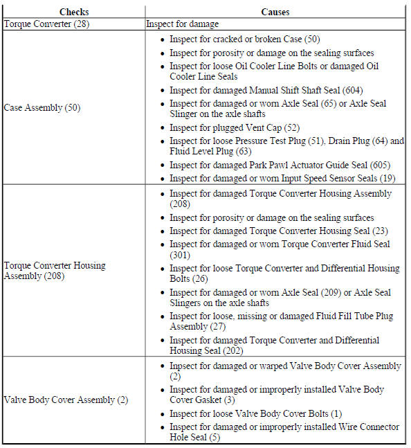
SHIFT INDICATOR INDICATES WRONG GEAR SELECTION
Shift Indicator Indicates Wrong Gear Selection
.jpg)
NO PARK
No Park
.jpg)

HARSH GARAGE SHIFT
Harsh Garage Shift
.jpg)
NO DRIVE IN ALL RANGES
No Drive in All Ranges

.jpg)
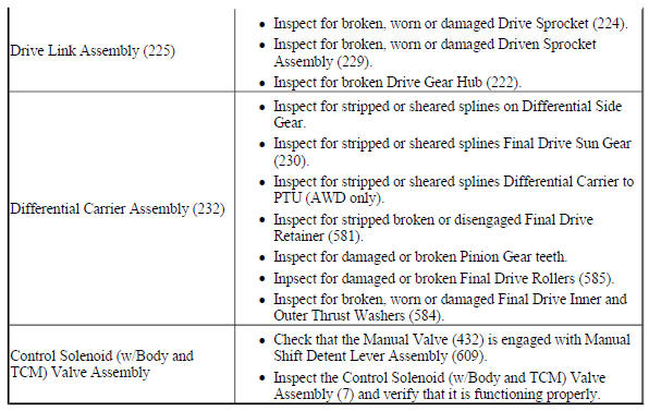
NO FIRST AND REVERSE GEARS
No First and Reverse Gears
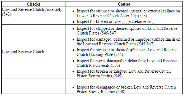
.jpg)
NO FIRST, SECOND, THIRD, AND FOURTH GEAR
No First, Second, Third, and Fourth Gear
.jpg)
.jpg)
NO SECOND AND SIXTH GEAR
No Second and Sixth Gear
.jpg)
HARSH OR LATE FIRST, SECOND, THIRD, AND FOURTH SHIFT
Harsh or Late First, Second, Third, and Fourth Shift
.jpg)
.jpg)
HARSH FIRST AND REVERSE SHIFT
Harsh First and Reverse Shift
.jpg)
NO THIRD, FIFTH, AND REVERSE GEAR
No Third, Fifth, and Reverse Gea
.jpg)
.jpg)
HARSH OR LATE SECOND AND SIXTH SHIFT
Harsh or Late Second and Sixth Shift
.jpg)
NO FOURTH, FIFTH, AND SIXTH GEAR
No Fourth, Fifth, and Sixth Gear
.jpg)
HARSH OR LATE THIRD, FIFTH, AND REVERSE SHIFT
Harsh or Late Third, Fifth, and Reverse Shift
.jpg)

HARSH FOURTH, FIFTH, AND SIXTH SHIFT
Harsh Fourth, Fifth, and Sixth Shift
.jpg)
NO TORQUE CONVERTER CLUTCH APPLY
No Torque Converter Clutch Apply
.jpg)
NO TORQUE CONVERTER CLUTCH RELEASE
No Torque Converter Clutch Release
.jpg)
HARSH TORQUE CONVERTER CLUTCH APPLY, OR INOPERATIVE OR NO ELECTRONICALLY CONTROLLED CAPACITY CLUTCH CONTROL
Harsh Torque Converter Clutch Apply, or Inoperative or No Electronically Controlled Capacity Clutch Control
.jpg)
NO REVERSE GEAR
No Reverse Gear

.jpg)
FLUID PRESSURE HIGH OR LOW
Fluid Pressure High or Low
.jpg)
.jpg)
READ NEXT:
 Repair instructions - off vehicle
Repair instructions - off vehicle
Fig. 1: Identifying Lift Plate & Holding Fixture
Lift Plate and Holding Fixture Installation
TORQUE CONVERTER REMOVAL
Fig. 2: View Of Torque Converter
Tor
Repair instructions - on vehicle
Manual shift detent lever with shaft position witch assembly replacement
Special Tools
DT-41229 Manual Shaft Pin Installer
For equivalent regional tools, refer to Special Tools .
Removal Procedure
R
Schematic wiring diagrams
Automatic transmission controls wiring schematics (ENCORE, MH8 OR MHB)
Module Power, Ground, Data Communication, and MIL
Fig. 1: Module Power, Ground, Data Communication, and MIL
Speed and Temperatu
SEE MORE:
Inflatable restraint sensing and diagnostic module programming and
Setup
The inflatable restraint sensing and diagnostic module (SDM) must be
programmed with the proper calibration
software. The module stores and utilizes this information however if it is not
properly configured with the
correct calibration software, the SDM will not control all of the vehicle
feature
Supplemental Inflatable Restraints - Description and operation
SUPPLEMENTAL INFLATABLE RESTRAINT SYSTEM DESCRIPTION AND OPERATION
SIR System Overview
The supplemental inflatable restraint (SIR) system supplements the protection
offered by the seat belts. The SIR
system contains an inflatable restraint sensing and diagnostic module (SDM), air
bags, seat belt p
