Buick Encore: Repair instructions - off vehicle
Repair instructions - off vehicle
.gif)
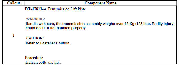
Fig. 1: Identifying Lift Plate & Holding Fixture
Lift Plate and Holding Fixture Installation
.jpg)
TORQUE CONVERTER REMOVAL
Fig. 2: View Of Torque Converter
Torque Converter Removal
.jpg)
CONTROL VALVE BODY ASSEMBLY REMOVAL
Control Valve Body Cover Removal
Fig. 3: View Of Control Valve Body Cover
Control Valve Body Cover Removal
.jpg)
Control Solenoid (With Body and TCM) Valve Assembly Removal

Fig. 4: View Of Control Solenoid (w/Body & TCM) Valve Assembly
Control Solenoid (With Body and TCM) Valve Assembly Removal
.jpg)
Control Valve Body Assembly Removal
Fig. 5: View Of Control Valve Body Assembly
Control Valve Body Assembly Removal
.jpg)
Input and output speed sensor removal
.gif)
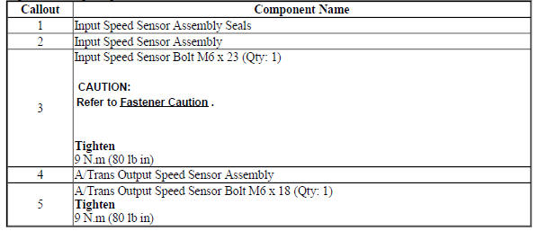
Fig. 6: View Of Input & Output Speed Sensor
Input and Output Speed Sensor Removal
.jpg)
TORQUE CONVERTER HOUSING WITH FLUID PUMP ASSEMBLY REMOVAL (NON HYBRID)

Fig. 7: View Of Torque Converter Housing & Fluid Pump Assembly
Torque Converter Housing with Fluid Pump Assembly Removal (Non Hybrid)
.jpg)
DIFFERENTIAL CARRIER REMOVAL (6T40)
Fig. 8: View Of Front Differential Carrier Assembly
Differential Carrier Removal (6T40)
.jpg)
DRIVE AND DRIVEN SPROCKET, DRIVE LINK, AND PARK PAWL REMOVAL (6T40)
Fig. 9: View Of Drive and Driven Sprocket, Drive Link & Park Pawl
Drive and Driven Sprocket, Drive Link, and Park Pawl Removal (6T40)
.jpg)
.gif)
INTERNAL COMPONENTS REMOVAL
Fig. 10: View Of Transmission Internal Components
Internal Components Removal
.jpg)
.jpg)
2-6 CLUTCH PISTON REMOVAL
Fig. 11: View Of 2-6 Clutch Piston & Attached Components
2-6 Clutch Piston Removal
.jpg)
.jpg)
MANUAL SHIFT DETENT LEVER WITH SHAFT POSITION SWITCH ASSEMBLY AND PARK PAWL ACTUATOR REMOVAL
Manual Shaft Detent (w/Shift Position Switch) Lever Assembly Removal

Fig. 12: Identifying Manual Shaft Detent Lever Assembly
Manual Shaft Detent (w/Shift Position Switch) Lever Assembly Removal
.jpg)
.jpg)
Park Pawl Actuator Guide Removal
.gif)
Fig. 13: Identifying Park Pawl Actuator Guide Components
Park Pawl Actuator Guide Removal
.jpg)
.jpg)
Manual shift shaft seal removal
.gif)
Fig. 14: identifying Manual Shift Shaft Seal
Manual Shift Shaft Seal Removal
.jpg)
INPUT SHAFT SUPPORT REPLACEMENT (GEN 2)
.gif)
Fig. 15: Input Shaft Support Components (Gen 2)
Input Shaft Support Replacement (Gen 2)
.jpg)
3-5-REVERSE AND 4-5-6 CLUTCH FLUID SEAL RING REPLACEMENT (GEN 2)

Fig. 16: 3-5-Reverse and 4-5-6 Clutch Fluid Seal Ring (Gen 2)
3-5-Reverse and 4-5-6 Clutch Fluid Seal Ring Replacement (Gen 2)
.jpg)
.jpg)
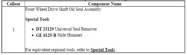
Front wheel drive shaft seal replacement - case side
.gif)
Fig. 17: View Of Case Side Front Wheel Drive Shaft Seal
Front Wheel Drive Shaft Seal Replacement - Case Side
.jpg)
TRANSMISSION CASE CLEANING AND INSPECTION
.gif)
Fig. 18: Cleaning & Inspecting Transmission Case
Transmission Case Cleaning and Inspection
.jpg)

.jpg)
MANUAL SHIFT DETENT LEVER WITH SHAFT POSITION SWITCH ASSEMBLY AND PARK PAWL ACTUATOR INSTALLATION
Park Pawl Actuator Guide Installation
.gif)
Fig. 19: View Of Park Pawl Actuator Guide & Seal
Park Pawl Actuator Guide Installation
.jpg)
.jpg)
Park Pawl Actuator Installation
.gif)
Fig. 20: Identifying Manual Shift Detent Lever with Shaft Position Switch
Assembly & Park Pawl Actuator
Park Pawl Actuator Installation
.jpg)
MANUAL SHIFT SHAFT SEAL INSTALLATION
Fig. 21: Identifying Manual Shift Shaft Seal
Manual Shift Shaft Seal Installation
.jpg)
2-6 CLUTCH PISTON INSTALLATION (6T40)
.gif)
Fig. 22: View Of 2-6 Clutch Piston Assembly
2-6 Clutch Piston Installation (6T40)
.jpg)
.jpg)
LOW AND REVERSE AND 1-2-3-4 CLUTCH HOUSING, LOW AND REVERSE CLUTCH ASSEMBLY, OUTPUT SUN GEAR, AND 2-6 CLUTCH PLATE DISASSEMBLE (GEN 2)
.gif)
Fig. 23: 1-2-3-4 Clutch Housing And Clutch Assembly Components
Low and Reverse and 1-2-3-4 Clutch Housing, Low and Reverse Clutch Assembly, Output Sun Gear, and 2-6 Clutch Plate Disassemble (Gen 2)
.jpg)
.jpg)
Input, reaction, and output carrier disassemble
.gif)
Fig. 24: Disassembled View Of Input, Reaction & Output Carrier
Courtesy of GENERAL MOTORS COMPANY
Input, Reaction, and Output Carrier Disassemble
.jpg)
3-5-REVERSE AND 4-5-6 CLUTCH HOUSING DISASSEMBLE (6T40 - GEN 2)
Turbine Shaft, Reluctor Wheel and Piston Removal
Fig. 25: Turbine Shaft, Reluctor Wheel And Piston
Turbine Shaft, Reluctor Wheel and Piston Removal
.jpg)
4-5-6 Clutch Plate Removal
.gif)
Fig. 26: 4-5-6 Clutch Plate Components
4-5-6 Clutch Plate Removal
.jpg)
4-5-6 Clutch Piston Removal

Fig. 27: 4-5-6 Clutch Piston Components
4-5-6 Clutch Piston Removal
.jpg)
.jpg)
Reluctor Wheel and Piston Removal
.gif)
Fig. 28: Disassembled View Of Reluctor Wheel & Piston
Reluctor Wheel and Piston Removal
.jpg)
.jpg)
3-5 Reverse Clutch Plate Removal
Fig. 29: 3-5 Reverse Clutch Plate Components
3-5 Reverse Clutch Plate Removal
.jpg)
.jpg)
3-5-REVERSE AND 4-5-6 CLUTCH HOUSING ASSEMBLE (6T40 - GEN 2)
4-5-6 Clutch Piston Installation
.gif)
Fig. 30: 4-5-6 Clutch Piston Components
4-5-6 Clutch Piston Installation
.jpg)
.jpg)
4-5-6 Clutch Fluid Dam Installation
.gif)
Fig. 31: 4-5-6 Clutch Fluid Dam
4-5-6 Clutch Fluid Dam Installation
.jpg)
.jpg)
3-5 Reverse Clutch Plates Installation

Fig. 32: 3-5 Reverse Clutch Plates
3-5 Reverse Clutch Plates Installation
.jpg)
Reluctor Wheel and Piston Installation
.gif)
Fig. 33: Exploded View Of Reluctor Wheel & Piston
Reluctor Wheel and Piston Installation
.jpg)
.jpg)
4-5-6 Clutch Plates Installation
.gif)
Fig. 34: 4-5-6 Clutch Plates
4-5-6 Clutch Plates Installation
.jpg)
Turbine Shaft Installation

Fig. 35: View Of Turbine Shaft
Turbine Shaft Installation
.jpg)
INPUT, REACTION, AND OUTPUT CARRIER ASSEMBLE (GEN 2)
Fig. 36: Input, Reaction, and Output Carrier Components (Gen 2)
Input, Reaction, and Output Carrier Assemble (Gen 2)
.jpg)
.jpg)
3-5-REVERSE AND 4-5-6 CLUTCH HOUSING, AND INPUT, REACTION, AND OUTPUT CARRIER INSTALLATION
Fig. 37: View Of 3-5-Reverse, 4-5-6 Clutch Housing, Input, Reaction & Output
Carrier Components
3-5-Reverse and 4-5-6 Clutch Housing, and Input, Reaction, and Output Carrier Installation
.jpg)
LOW AND REVERSE CLUTCH ASSEMBLY AND LOW AND REVERSE CLUTCH PLATE INSTALLATION
.gif)
Fig. 38: View Of Low and Reverse Clutch Assembly
Low and Reverse Clutch Assembly and Low and Reverse Clutch Plate Installation
.jpg)
.jpg)
Low and reverse and 1-2-3-4 clutch housing isassemble
Low and Reverse Clutch Piston Removal
.gif)
Fig. 39: View Of Low & Reverse Clutch Piston
Low and Reverse Clutch Piston Removal
.jpg)
.jpg)
1-2-3-4 Clutch Piston Removal
.gif)
Fig. 40: View Of 1-2-3-4 Clutch Piston
1-2-3-4 Clutch Piston Removal
.jpg)
LOW AND REVERSE AND 1-2-3-4 CLUTCH HOUSING CLEANING AND INSPECTION
.gif)
Fig. 41: Identifying Low and Reverse & 1-2-3-4 Clutch Housing
Low and Reverse and 1-2-3-4 Clutch Housing Cleaning and Inspection
.jpg)
LOW AND REVERSE AND 1-2-3-4 CLUTCH HOUSING ASSEMBLE
1-2-3-4 Clutch Piston Installation
.gif)
Fig. 42: View Of 1-2-3-4 Clutch Piston
1-2-3-4 Clutch Piston Installation
.jpg)
.jpg)
Low and Reverse Clutch Piston Installation
.gif)
Fig. 43: View Of Low & Reverse Clutch Piston
Low and Reverse Clutch Piston Installation
.jpg)
.jpg)
LOW AND REVERSE AND 1-2-3-4 CLUTCH HOUSING, AND 1-2-3-4 CLUTCH PLATE INSTALLATION (6T40)
.gif)
Fig. 44: View Of Low and Reverse & 1-2-3-4 Clutch Housing & Attached
Components
Low and Reverse and 1-2-3-4 Clutch Housing, and 1-2-3-4 Clutch Plate Installation (6T40)
.jpg)

Drive sprocket, driven sprocket, and drive link cleaning and inspection

Fig. 45: View Of Drive Sprocket, Driven Sprocket & Drive Link
Drive Sprocket, Driven Sprocket, and Drive Link Cleaning and Inspection
.jpg)
DRIVE AND DRIVEN SPROCKET, DRIVE LINK, AND PARK PAWL INSTALLATION (6T40)
.gif)
Fig. 46: View Of Drive Sprocket, Driven Sprocket & Park Paw
Drive and Driven Sprocket, Drive Link, and Park Pawl Installation (6T40)
.jpg)
.jpg)
FRONT DIFFERENTIAL CARRIER CLEANING AND INSPECTION
.gif)
Fig. 47: View Of Front Differential Carrier
Front Differential Carrier Cleaning and Inspection
.jpg)
.jpg)
FRONT DIFFERENTIAL CARRIER INSTALLATION (6T40)
.gif)
Fig. 48: View Of Front Differential Carrier Components
Front Differential Carrier Installation (6T40)
.jpg)
TRANSMISSION FLUID PUMP, FRONT DIFFERENTIAL CARRIER BAFFLE, AND FRONT DIFFERENTIAL RING GEAR REMOVAL (6T40)

Fig. 49: View Of Transmission Fluid Pump, Front Differential Carrier Baffle &
Components
Transmission Fluid Pump, Front Differential Carrier Baffle, and Front Differential Ring Gear Removal (6T40)

.jpg)
FRONT WHEEL DRIVE SHAFT SEAL REMOVAL - TORQUE CONVERTER HOUSING SIDE

Fig. 50: Front Wheel Drive Shaft Seal - Torque Converter Housing Side
Front Wheel Drive Shaft Seal Removal - Torque Converter Housing Side
FRONT DIFFERENTIAL CARRIER BEARING REMOVAL (AWD)
Fig. 51: Front Differential Carrier Bearing (AWD)
Front Differential Carrier Bearing Removal (AWD)
.jpg)
FRONT DIFFERENTIAL CARRIER BEARING INSTALLATION (AWD)
.gif)
Fig. 52: Front Differential Carrier Bearing (AWD)
Front Differential Carrier Bearing Installation (AWD)
.jpg)
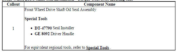
FRONT WHEEL DRIVE SHAFT SEAL INSTALLATION - TORQUE CONVERTER HOUSING SIDE

Fig. 53: Front Wheel Drive Shaft Seal - Torque Converter Housing Side
Front Wheel Drive Shaft Seal Installation - Torque Converter Housing Side
TORQUE CONVERTER HOUSING CLEANING AND INSPECTION
Fig. 54: Identifying Torque Converter Housing Inspection Areas
Torque Converter Housing Cleaning and Inspection
.jpg)
TRANSMISSION FLUID PUMP DISASSEMBLE (6T40)
Fluid Filter Assembly and Torque Converter Fluid Seal Disassemble
.gif)
Fig. 55: View Of Fluid Filter Assembly & Torque Converter Fluid Seal
Fluid Filter Assembly and Torque Converter Fluid Seal Disassembl
.jpg)
.jpg)
Fluid Pump Disassemble
.gif)
Fig. 56: Transmission Fluid Pump & Components
Fluid Pump Disassemble
.jpg)
.jpg)
FLUID PUMP SELECTIVE MEASUREMENT
.gif)
Fig. 57: Measuring Fluid Pump Components
Fluid Pump Selective Measurement
.jpg)
.jpg)
TRANSMISSION FLUID PUMP ASSEMBLE (6T40)
Fluid Pump w/Valve Trains Assemble
.gif)
Fig. 58: Fluid Pump W/Valve Trains Assembly
Fluid Pump w/Valve Trains Assemble
.jpg)
Torque Converter Fluid Seal and Fluid Filter Assembly Assemble
Fig. 59: View Of Torque Converter Fluid Seal & Fluid Filter Assembly
Torque Converter Fluid Seal and Fluid Filter Assembly Assemble
.jpg)
TRANSMISSION FLUID PUMP, FRONT DIFFERENTIAL CARRIER BAFFLE, AND FRONT DIFFERENTIAL RING GEAR INSTALLATION (6T40)
Fig. 60: Identifying Transmission Fluid Pump, Front Differential Carrier
Baffle & Front Differential Ring Gear
Transmission Fluid Pump, Front Differential Carrier Baffle, and Front Differential Ring Gear Installation (6T40)
.jpg)
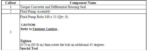
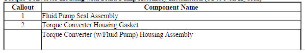
TORQUE CONVERTER HOUSING WITH FLUID PUMP ASSEMBLY INSTALLATION (6T40 NON HYBRID)
Fig. 61: Identifying Torque Converter Housing & Fluid Pump Assembly
Torque Converter Housing with Fluid Pump Assembly Installation (6T40 Non Hybrid)
.jpg)
INPUT AND OUTPUT SPEED SENSOR INSTALLATION

Fig. 62: Identifying Input & Output Speed Sensor
Input and Output Speed Sensor Installation
CONTROL VALVE BODY ASSEMBLY DISASSEMBLE (GEN 2)
.gif)
Fig. 63: Control Valve Body (Gen 2)
Control Valve Body Assembly Disassemble (Gen 2)
.jpg)
CONTROL VALVE BODY CLEANING AND INSPECTION (GEN 2)
.gif)
Fig. 64: Control Valve Body Cleaning and Inspection (Gen 2)
Control Valve Body Cleaning and Inspection (Gen 2)
.jpg)
.jpg)
CONTROL VALVE CHANNEL PLATE CLEANING AND INSPECTION (6T40 - GEN 2)
.gif)
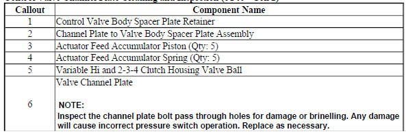
Fig. 65: Control Valve Channel Plate Cleaning and Inspection
Control Valve Channel Plate Cleaning and Inspection (6T40 - Gen 2)

Control valve body assembly assemble (gen 2)
Fig. 66: Control Valve Body And Components
Control Valve Body Assembly Assemble (Gen 2)
.jpg)
CONTROL VALVE BODY ASSEMBLY INSTALLATION

Fig. 67: View Of Control Valve Body Assembly Attachments
Control Valve Body Assembly Installation
.jpg)
.jpg)
CONTROL SOLENOID VALVE AND TRANSMISSION CONTROL MODULE ASSEMBLY INSTALLATION
.gif)
Fig. 68: Identifying Control Solenoid Valve & TCM Bolt Tightening Sequence
Control Solenoid Valve and Transmission Control Module Assembly Installation
.jpg)
.jpg)
CONTROL VALVE BODY COVER INSTALLATION
.gif)
Fig. 69: Identifying Control Valve Body Cover Bolt Tightening Sequence
Control Valve Body Cover Installation
.jpg)
.jpg)
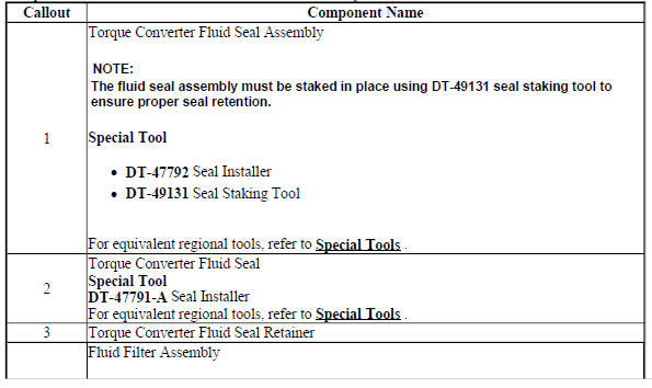
TORQUE CONVERTER FLUID SEAL REPLACEMENT
.gif)
Fig. 70: View Of Torque Converter Fluid Seal & Retainer
Torque Converter Fluid Seal Replacement
.jpg)
.jpg)
TORQUE CONVERTER INSTALLATION
.gif)
Fig. 71: View Of Torque Converter
Torque Converter Installation
.jpg)
.jpg)
LIFT PLATE AND HOLDING FIXTURE REMOVAL
.gif)
Fig. 72: Identifying Lift Plate & Holding Fixture
Lift Plate and Holding Fixture Removal
.jpg)
.jpg)
READ NEXT:
 Repair instructions - on vehicle
Manual shift detent lever with shaft position witch assembly replacement
Special Tools
DT-41229 Manual Shaft Pin Installer
For equivalent regional tools, refer to Special Tools .
Removal Procedure
R
Schematic wiring diagrams
Automatic transmission controls wiring schematics (ENCORE, MH8 OR MHB)
Module Power, Ground, Data Communication, and MIL
Fig. 1: Module Power, Ground, Data Communication, and MIL
Speed and Temperatu
Description and operation
Definitions and abbreviations
Throttle Positions
Engine Braking
A condition where the engine is used to slow the vehicle by manually
downshifting during a zero throttle
coastdown.
Full Throttle Downs
SEE MORE:
Specifications
BODY CONTROL MODULE SCAN TOOL INFORMATION
Body Control Module Scan Tool Data Parameters
Body Control Module Scan Tool Output Controls
CHASSIS CONTROL MODULE SCAN TOOL INFORMATION
Chassis Control Module Scan Tool Data Parameters
Chassis Control Modu
Rear Window Wiper/Washer
The rear wiper/washer controls are
on the end of the windshield wiper
lever.
ON : Press the upper portion of the
button for continuous rear window
wipes.
OFF : The rear wiper turns off when
the button is returned to the middle
position.
INT : Press the lower portion of the
button for rear interm
