Buick Encore: Sunroof - Repair instructions
SUNROOF AIR DEFLECTOR REPLACEMENT

Fig. 3: Sunroof Air Deflector
Sunroof Air Deflector Replacement
.jpg)
SUNROOF AIR DEFLECTOR COVER REPLACEMENT
.gif)
Fig. 4: Sunroof Air Deflector Cover
Sunroof Air Deflector Cover Replacement
.jpg)
SUNROOF DRAIN INSPECTION AND CLEANING
Drain Hose Routing
NOTE: If the headliner is wet DO NOT remove any interior trim. Do the Plugged Drain Hose test first.
A drain trough encircles the sunroof window panel and water is drained off by the drain hoses located at each corner of the housing. A drain channel spans across the sunroof module at the rear of the window panel and directs water into the trough.
- The front drain hoses are routed out of the left and right corners of the plenum. The front hoses are installed through a rubber grommet that seals the hose tightly in the plenum.
- The rear drain hoses are routed through the left and right rear lower
quarter panel and out of the body.
The rear hoses are installed through a rubber grommet that seals the hose tightly in the quarter panel.
Plugged Drain Hose
In some vehicle it may be necessary to clean the sunroof drain hose by applying air from the lower end of the drain hose outlet instead of the upper drain hose outlet.
If a waterleak has occurred check for a plugged sunroof module drain hose at each corner of drainage system by doing the following:
- Open the sunroof window.
- Locate each sunroof module drain hose outlet area.
- With a visual look, ensure that all the hoses are attached to the sunroof module drain outlet.
- Cover all of the interior before air is apply to the drain hose.
- To test for blockage, pour a small container of water into the module housing drain trough. Check each corner to confirm the drain hose is draining water if not go to step number 6.
WARNING: Wear safety glasses in order to avoid eye damage.
- Use compressed air, 241 kPa (35 psi) or less to blow out any drain hose that is plugged.
- Test the system again.
- If remain plugged remove the blockage using the following steps.
- Push mechanics wire through the hose to remove the obstruction.
- Use compressed air in order to blow out any remaining material.
- If the hose remains plugged, check to see it is properly routed and does not have a kink. Refer to Sunroof Housing Front Drain Hose Replacement, or Sunroof Housing Rear Drain Hose Replacement.
Disconnected Drain Hose
Inspect the drainage system for disconnected drain hoses. Complete the following steps in order to obtain partial access to drain hoses and check for a disconnected hose.
- Open the sunroof window panel.
- Lower the headliner as needed. Refer to Headlining Trim Panel Replacement (With Sunroof, Encore) , Headlining Trim Panel Replacement (With Sunroof, Encore) .
- Connect any disconnected hoses. If tie straps are required, connect the hose and apply tie strap.
- Ensure that the rear drain hoses are properly routed in the metal roof slot and taped in place.
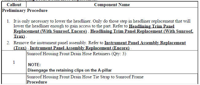
SUNROOF HOUSING FRONT DRAIN HOSE REPLACEMENT
.gif)
Fig. 5: Sunroof Housing Front Drain Hose
Sunroof Housing Front Drain Hose Replacement
.jpg)
SUNROOF HOUSING REAR DRAIN HOSE REPLACEMENT
Fig. 6: Sunroof Housing Rear Drain Hose
Sunroof Housing Rear Drain Hose Replacement
.jpg)
SUNROOF MODULE ASSEMBLY REPLACEMENT

Fig. 7: Sunroof Module assembly
Sunroof Module Assembly Replacement
.jpg)
.jpg)
SUNROOF MOTOR/ACTUATOR INITIALIZATION/TEACH PROCESS
NOTE: If the sunroof motor is new, cycle the sunroof seven (7) times to teach the motor/actuator initialization process.
Perform the initialization/teach procedure on a reinstall motor or a new motor.
Ensure the electrical harness on the headliner is connected to the sunroof motor, battery power is applied, and the ignition switch is ON.
NOTE: If the sunroof window doesn't go to the vent open position first time, release the switch and press the switch again.
- Press and hold the sunroof switch to the vent open position until the sunroof window stops in the vent open position.
- Again press and hold the sunroof switch to the vent open position for at least 10 seconds, then the window should move slightly.
- Verify the sunroof operation
If the initialization/teach procedure is not carried out completely, it has to be started again.
SUNROOF ACTUATOR MOTOR REPLACEMENT

Fig. 8: Sunroof Window Motor 7 Bolts
Sunroof Actuator Motor Replacement
.jpg)
SUNROOF SUNSHADE REPLACEMENT

Fig. 9: Sunroof Sunshade & Mounting Components
Sunroof Sunshade Replacement

SUNROOF TILT POSITION SWITCH REPLACEMENT
Fig. 10: Sunroof Tilt Position Switch
Sunroof Tilt Position Switch Replacement

SUNROOF SWITCH REPLACEMENT

Fig. 11: Sunroof Switch
Sunroof Switch Replacement

SUNROOF WINDOW HEIGHT AND OPENING FIT ADJUSTMENT
NOTE: Correct adjustment cannot be achieved if the sunroof window is closed from vent position.
- Cycle the sunroof window from full open to closed position.

Fig. 12: View Of Sunroof Window & Opening Fit
NOTE: Do Not remove or lower headliner to access sunroof window screws.
- Loosen the adjusting screws on the window.
- Adjust the corners of the front window panel using the following guidelines:
- Adjust the front of the sunroof window to 0.0 mm - 1.0 mm (0.0 in - 0.04 in ) below the top surface of the roof panel.
- Adjust the rear center line of the sunroof window to 2 mm to 3 mm (0 .08 in to 0.12 in ) below the top surface of the roof panel.
CAUTION: Refer to Fastener Caution .
- Tighten the sunroof window adjustment screws to 5 N.m (44 lb in).
- Cycle sunroof window through all positions.
- Inspect the sunroof window adjustment. Adjust if necessary
SUNROOF WINDOW REPLACEMENT

Fig. 13: Sunroof Window & Bolts
Sunroof Window Replacement


READ NEXT:
 Sunroof - Description and operation
SUNROOF DESCRIPTION AND OPERATION
The tilt/slide sunroof consists of a moving glass panel and a manual sunshade.
In the tilt/slide sunroof system
the rear of the glass tilts up for venting and slides
Vehicle Access
SCHEMATIC WIRING DIAGRAMS
SPECIFICATIONS
Fastener Tightening Specifications
SCHEMATIC WIRING DIAGRAMS
DOOR LOCK/INDICATOR WIRING SCHEMATICS (ENCORE)
Switches and Ajar Indicator
Fig. 1: Switches an
Vehicle access - Diagnostic information and procedures
DTC B252C: Child security lock switch circuit
DIAGNOSTIC CODE INDEX
Diagnostic Instructions
Perform the Diagnostic System Check - Vehicle prior to using this
diagnostic procedure.
Review Strate
SEE MORE:
Engine controls and fuel - 1.4l - Repair instructions
Brake pedal position sensor learn
Calibration Criteria
NOTE:
Do not apply the brake pedal during the brake pedal position sensor
calibration
procedure. Any movement of the brake pedal during this procedure will cause
the calibration procedure to fail. If this occurs, the brake pedal position
senso
Seat heating and cooling - Description and operation
HEATED SEATS DESCRIPTION AND OPERATION
Heated Seat Components
The driver and passenger heated seats consist of the following components:
Left heated seat switch
Right heated seat switch
HVAC control module
Seat memory control module or seat heating control module
Driver seat cushion heating el
